Systematic Duct and Airflow Troubleshooting
Duct and airflow problems rarely identify themselves with one measurement. Low airflow can result from blower setup, filter or coil restriction, duct resistance, leakage, closed dampers, poor fittings, flexible-duct installation, terminal selection, or a combination of conditions. A comfort complaint can also originate with room loads, equipment capacity, control sequence, return paths, or building pressure rather than the visible register.
This final lesson combines visual inspection, total external static pressure, blower data, component pressure drop, duct pressure, delivered airflow, room pressure, temperature, humidity, leakage testing, and customer observations into one repeatable diagnostic process. The objective is not to collect every possible reading; it is to select measurements that separate competing causes, make the smallest justified repair, and prove the final system performs correctly.
What You Will Learn
By the end of this lesson you should be able to:
Define the complaint precisely.
Identify the affected rooms, operating modes, weather conditions, door positions, blower stages, times, sounds, odors, and previous system changes.
Establish a repeatable test condition.
Document equipment configuration, filter, panels, dampers, doors, registers, zones, blower command, and system mode before interpreting measurements.
Separate system and local problems.
Determine whether the defect affects the complete air circuit, the supply or return side, one trunk, one branch, one room, or one terminal.
Build a pressure and airflow profile.
Use TESP, component pressure drops, blower data, duct static pressure, terminal airflow, and room pressure to locate abnormal resistance or air loss.
Match evidence with a repair.
Correct the demonstrated cause without masking restrictions, disturbing unrelated branches, or changing blower setup without supporting data.
Verify the completed system.
Repeat the original measurements, check equipment and room performance, document the final configuration, and confirm that the complaint has been resolved.
Test a Cause—Do Not Collect Unrelated Numbers
Every measurement should answer a question. TESP asks how much external resistance the blower is operating against. A blower table relates that resistance and the selected setting to airflow when the equipment configuration matches the published data. A pressure drop brackets resistance across a component or section. A terminal reading evaluates delivery to a room. Room-to-hall pressure tests the return path. Duct leakage testing evaluates duct-system airtightness under a defined procedure.
Observe
Listen to the customer, operate the system, inspect the equipment and duct path, and identify facts that narrow the problem before installing instruments.
Predict
State what measurements should look like if each suspected cause is true. This prevents a familiar fault from becoming the conclusion before it is tested.
Measure
Select safe test locations, suitable instruments, correct pressure references, and representative operating conditions. Record the setup with the reading.
Compare
Use manufacturer data, design documents, applicable standards, commissioning records, previous baselines, and measurements from known-good paths rather than unsupported universal values.
Correct
Repair the condition supported by the evidence while preserving safety, equipment requirements, air balance, insulation, sealing, and service access.
Verify
Repeat the measurement that proved the problem and check related system values because one repair can change blower airflow and parallel branch distribution.
High TESP identifies excessive resistance across the defined test boundary, but it does not name the restrictive component. Low terminal airflow identifies poor delivery, but it does not reveal whether the cause is upstream airflow, branch resistance, leakage, damper position, terminal performance, or room pressure.
Move from the Complaint to the Smallest Affected Section
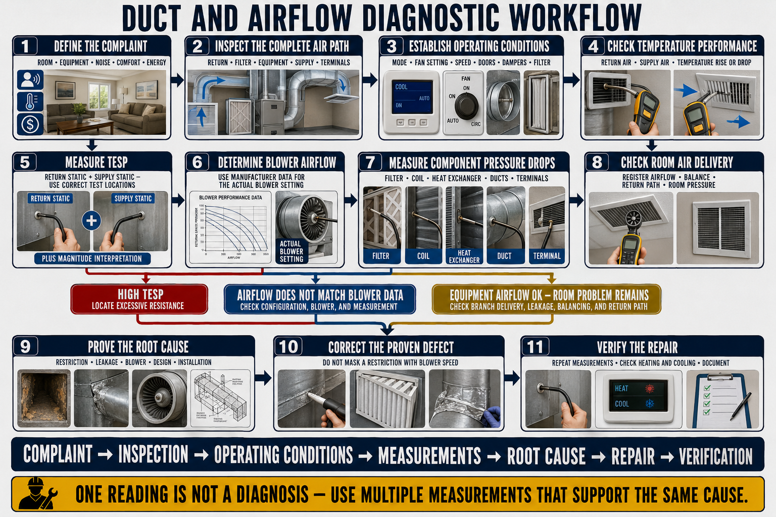
Confirm the complaint.
Operate the system under the condition that produces the concern when practical and record who is affected, where, when, and in which mode or stage.
Identify the equipment and design intent.
Record model numbers, blower type, airflow setting, thermostat configuration, accessories, filter, zoning, design airflow, and available startup or balance information.
Inspect before testing.
Find obvious disconnections, closed dampers, blocked grilles, dirty components, missing panels, collapsed flex, poor fittings, leakage, insulation damage, and recent alterations.
Establish total airflow and pressure.
Measure return and supply external static pressure at correct boundaries, calculate TESP, and determine blower airflow using applicable manufacturer data or another validated method.
Locate the pressure consumer.
Bracket filters, coils, equipment sections, trunks, dampers, accessories, and suspect duct sections to identify where an abnormal share of pressure is being used.
Evaluate distribution.
Measure terminal airflow, duct static pressure, temperatures, room-to-hall pressure, air patterns, and sound at the smallest level needed to explain the complaint.
Repair the demonstrated cause.
Correct the restriction, leakage, installation defect, balance, control, return path, terminal, or blower setup supported by the complete evidence.
Repeat and document.
Restore the final operating configuration, repeat critical measurements, verify safety and comfort, label adjustments, and record results for future service.
Make Every Before-and-After Reading Comparable
System Mode
Record cooling, heat-pump heating, auxiliary heat, gas heat, ventilation, dehumidification, fan-only, stage, compressor capacity, and the time allowed for operation to stabilize.
Blower Command
Identify selected tap, speed, torque setting, airflow target, profile, delay, zoning command, and any communicating-control request rather than relying on nominal equipment tonnage.
Filter and Panels
Record filter model, size, condition, orientation, number of filters, bypass gaps, access-panel position, and cabinet assembly because each can change pressure and airflow.
Dampers and Zones
Document zone calls, bypass position, outdoor-air devices, balancing dampers, fire or smoke dampers, registers, grilles, and any temporary test positions.
Doors and Building
Record interior and exterior door positions, exhaust appliances, fireplaces, ventilation systems, and access panels when they can influence return paths or building pressure.
Indoor and Outdoor Conditions
Measure temperatures and humidity needed to interpret equipment operation, duct heat gain or loss, condensation, capacity, and whether the complaint is reproducible.
A clean filter with all zones open is not directly comparable with a loaded filter and one small zone calling. Record the configuration for every important reading and restore the intended final condition before verification.
Let the Scope of the Symptom Guide the First Test
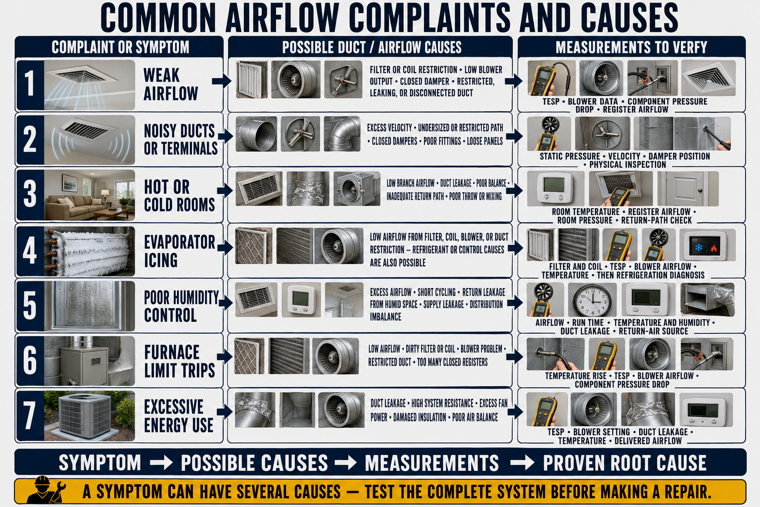
Weak Airflow Everywhere
Check blower command and operation, rotation or wheel condition where applicable, TESP, filter, coil, equipment configuration, return restriction, supply restriction, zoning, bypass, and major leakage.
One Weak Outlet
Check terminal, boot, branch damper, takeoff, flex compression, sharp bends, leakage, crushing, foreign material, branch size, and pressure available at the takeoff.
Several Nearby Weak Outlets
Look for a shared trunk, zone damper, transition, junction, fitting, flex section, return path, or balance condition serving the affected group.
Door-Position Complaint
Measure room-to-hall pressure and terminal airflow with the door open and closed, then evaluate dedicated returns, transfer grilles, jump ducts, and other approved return paths.
Excessive Air Noise
Evaluate total and local velocity, restrictive grilles, closed dampers, filter area, terminal selection, abrupt fittings, turbulent inlet conditions, blower airflow, and equipment vibration.
Uneven Temperatures
Compare room loads, delivered airflow, supply temperature, runtime, terminal pattern, solar exposure, envelope leakage, return paths, zoning, and thermostat influence.
Humidity or Condensation
Check cooling airflow, runtime, latent operation, duct leakage, insulation, vapor-retarder continuity, ambient dew point, surface temperature, drainage, and moisture entry.
Limit Trips or Coil Freezing
Immediately protect the equipment, then evaluate airflow, filter and coil restriction, blower operation, duct resistance, dampers, controls, refrigerant-system conditions, and manufacturer limits.
Find Installation Defects Before They Become Instrument Problems
Return Path
Trace grilles, filters, cavities, ducts, flex runs, dampers, plenums, and cabinet connections to the blower while checking blockage, leakage, collapse, contamination, and inadequate free area.
Equipment
Inspect blower wheel and housing, motor and control settings, heat exchanger or electric heat section, evaporator coil, drain pan, cabinets, access panels, and installed accessories.
Supply Path
Trace plenum, transitions, trunks, zone dampers, branch fittings, flex ducts, boots, registers, and insulation for restriction, leakage, damage, poor geometry, or unplanned alteration.
Terminal and Room
Check grille selection, blade and damper position, furniture, curtains, rugs, doors, return paths, room use, envelope changes, and whether the supply pattern reaches the occupied zone.
Evidence of Change
Look for new filters, remodels, additions, replaced equipment, added zoning, closed branches, duct repairs, insulation changes, new flooring, furniture, or occupant adjustments that align with complaint timing.
Safety and Access
Identify energized equipment, rotating parts, hot surfaces, sharp metal, weak ceilings, confined spaces, contaminated insulation, combustion risks, and fall hazards before opening or entering the system.
Photograph or mark damper positions, wiring selections, control settings, filter orientation, zone state, and disconnected or damaged ducts before correction. The original condition may explain the measurements and protect the diagnostic record.
Start at the Blower—Then Bracket the Abnormal Section
Review the measurement procedures from Lesson 8 and the TESP and blower-data process from Lesson 9. Correct probe placement, pressure reference, equipment boundary, blower setting, and manufacturer data are essential before the numbers can guide a repair.
Restriction Before the Blower
An unusually large negative magnitude directs attention to return grilles, filters when outside the equipment boundary, return ducts, dampers, fittings, and cabinet inlets.
Restriction After the Equipment
An unusually large positive value directs attention to coils or accessories when outside the defined boundary, plenums, supply trunks, dampers, transitions, branches, and terminals.
High TESP and Low Airflow
Excess resistance is likely, especially with blowers whose airflow falls as static rises. Use component and section pressure drops to locate where the pressure is consumed.
High TESP and Near-Target Airflow
A constant-airflow blower may increase speed and power to maintain its target within its capability. Noise, energy use, motor loading, and loss of airflow margin can reveal the restriction.
Low TESP and Low Airflow
Consider an incorrect blower command, motor or wheel problem, wrong equipment configuration, major duct disconnection or bypass, incorrect pressure locations, or a system that is moving little air and therefore creating little pressure.
Acceptable TESP and Local Complaint
Investigate branch pressure, fittings, dampers, leakage, terminal airflow, terminal pattern, room return path, load, and building conditions. Whole-system static cannot prove every room is correct.
Use the correct model, motor, blower setting, airflow target, cabinet configuration, coil, filter and accessory boundary, voltage condition, and manufacturer table. Nameplate maximum, rated test condition, and recommended operating range do not necessarily mean the same thing.
Find Where the Available Pressure Is Being Used
Use the procedures from Lesson 10 to compare pressure immediately before and after a component or duct section. A pressure drop becomes diagnostic only when airflow, test locations, component condition, and a suitable comparison are known.
Filter
Compare the installed filter pressure drop with exact product data, design allowance, a clean baseline, and the measured airflow while checking area, bypass, rack geometry, and multiple-filter arrangement.
Evaporator Coil
Compare pressure drop at verified airflow with applicable manufacturer data or a clean, dry baseline while considering wet-coil operation, fouling, icing, face velocity, and measurement access.
Heat Exchanger or Electric Heat
Use the manufacturer’s boundary and operating data. Do not drill unsafe test ports or infer internal condition from external pressure without understanding cabinet construction.
Air Cleaner and Accessories
Energy-recovery connections, ultraviolet assemblies, humidifiers, bypass ducts, sound devices, zoning equipment, and aftermarket accessories can create unexpected pressure loss or leakage.
Return or Supply Section
Pressure readings at selected points can bracket a trunk, transition, damper, flex run, or fitting group and reveal where an abrupt loss occurs.
Terminal
A register, grille, diffuser, boot, or filter grille can create high local loss. Compare exact terminal performance and free area rather than nominal dimensions alone.
A component designed to perform work on the airstream can have a substantial normal pressure drop. Diagnose excess by comparing the measured value at known airflow with applicable manufacturer data, design information, or a valid baseline.
Motor Type Changes the Symptom—Not the Duct Restriction
PSC Blower
As external resistance rises, airflow generally falls along the selected blower curve. Motor speed is not a direct airflow measurement, and changing taps must remain within equipment requirements.
Constant-Torque ECM
The motor applies a programmed torque response, but airflow still varies with system resistance and blower setup. Use the exact manufacturer’s performance data.
Constant-Airflow ECM
The control attempts to maintain a programmed airflow by changing motor output within its limits. Rising static can increase speed, sound, and power before airflow falls substantially.
Communicating and Variable Capacity
Airflow targets can change with capacity, mode, humidity control, temperature, zoning, and control logic. Record commanded operation rather than assuming full airflow.
A higher setting can increase airflow, but it may also raise static pressure, sound, leakage, fan power, draft, and equipment temperatures outside the intended range. Prove that the system needs a different airflow and can support it before changing the setting.
When the Blower Is Correct, Follow the Air to the Complaint
Confirm trunk conditions.
Measure available static pressure where the branch begins and compare affected and unaffected sections before assuming the branch duct alone is responsible.
Inspect the takeoff and damper.
Verify fitting geometry, damper position, actuator operation, obstruction, leakage, and whether the branch receives a stable inlet condition.
Trace the branch.
Check size, length, elbows, flex compression, sag, kinks, crushing, support, insulation, junctions, leakage, and unrecorded modifications.
Evaluate the boot and terminal.
Inspect entry geometry, debris, seal, terminal free area, blade setting, face damper, pressure drop, sound, and air pattern.
Measure delivered airflow.
Use a suitable flow hood, compensated hood, traverse, or other validated method and compare with the room design or balance target.
Test the room return path.
Measure room-to-hall pressure and terminal airflow with representative door positions, then evaluate dedicated returns, transfer grilles, jump ducts, or other approved paths.
Closing good branches to compensate for a crushed, disconnected, undersized, or obstructed branch can raise system resistance and reduce total airflow. Repair the abnormal path before final balancing.
Verify Every Required Operating Mode
Cooling
Airflow affects sensible capacity, moisture removal, coil temperature, refrigerant-system operation, supply temperature, and condensation risk. Verify the refrigeration system only after airflow is known.
Gas or Oil Heat
Airflow affects temperature rise, heat-exchanger temperature, limit operation, venting interactions, and delivered-air temperature. Use the equipment rating and manufacturer procedures.
Electric Heat
Verify airflow, heater staging, sequencer or control operation, temperature rise, current, and safety limits according to equipment data and electrical safety procedures.
Heat-Pump Heating
Capacity, supply temperature, defrost, auxiliary heat, outdoor conditions, compressor stage, and blower control can change the perceived airflow and room response.
Zoned Operation
Test representative minimum and maximum zone combinations. A system acceptable with all zones open can exceed pressure or airflow limits when one small zone calls.
Dehumidification
Reduced airflow may be an intentional control strategy, but it must remain within equipment limits and avoid coil freezing, excessive static, poor distribution, or unacceptable room pressure.
Correct the Cause Without Creating a New Imbalance
Restore Maintenance Condition
Replace or clean approved filters, coils, blower components, grilles, and heat-transfer surfaces using manufacturer procedures, then establish a new pressure baseline.
Reduce Duct Resistance
Correct undersized or blocked paths, abrupt fittings, flex compression, sharp bends, poor transitions, restrictive grilles, closed dampers, and insufficient return area.
Repair Leakage
Mechanically reconnect ducts, seal the actual air boundary with approved materials, restore insulation and vapor control, and repeat the appropriate leakage test.
Restore Distribution
Correct branch defects and return paths before adjusting accessible balancing dampers, then remeasure every affected terminal and total system airflow.
Correct Blower Setup
Change airflow settings only from supported equipment, load, capacity, temperature, humidity, and duct-performance evidence while respecting the manufacturer’s allowable range.
Escalate Design Problems
When the installed equipment, pressure budget, effective length, duct sizes, terminals, return strategy, or room loads cannot meet requirements, recommend a documented redesign rather than repeated minor adjustments.
Opening a restriction, sealing a leak, changing a blower setting, replacing a filter, or moving a damper changes the operating point and distribution. Always recheck system-level and room-level performance after a significant correction.
Prove the Repair Under the Final Operating Configuration
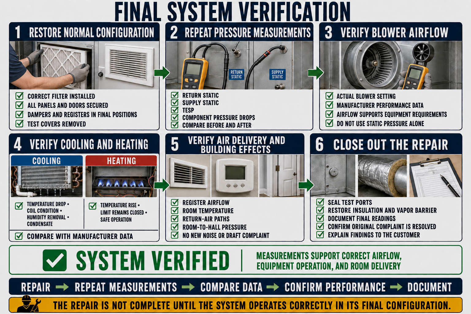
Restore normal assembly.
Install the final filter, close panels, seal test ports, restore insulation, reconnect controls, remove temporary seals, and place dampers, zones, registers, doors, and accessories in intended positions.
Repeat TESP and blower airflow.
Use the same valid boundaries and operating mode to confirm the final resistance and airflow against manufacturer data and the system target.
Verify equipment performance.
Check applicable temperature rise or drop, refrigerant performance, motor operation, heat staging, limits, condensate management, controls, and safety devices.
Verify distribution.
Remeasure critical supply and return terminals, confirm branch balance, inspect air patterns, listen for noise, and verify that dampers remain accessible and labeled.
Verify rooms and building pressure.
Test closed-room pressure, return paths, representative room temperatures, door effects, exhaust interactions, and the original occupied-space complaint.
Document the final state.
Record before-and-after readings, instrument and method, operating conditions, repairs, filter information, blower and damper settings, remaining limitations, and recommended follow-up.
Testing with an access panel removed, no filter installed, all zone dampers forced open, a door propped open, or a register removed may isolate a restriction, but it does not prove acceptable operation in the customer’s normal configuration.
Follow the Evidence Instead of the Symptom
High Return Pressure
The system has low airflow and a large negative return static magnitude. Pressure drop across the filter is excessive at the measured airflow, and removing the loaded filter for a brief controlled diagnostic test reduces TESP. Correct the filter-area or loading problem, install the final approved filter, and retest.
High Supply Pressure
Return pressure is reasonable, but positive supply static is high. Pressure readings bracket a nearly closed zone damper. Repair the damper or control, then verify TESP, airflow, zoning sequences, bypass arrangement if present, and all affected rooms.
Normal TESP, Weak Bedroom
Whole-system airflow is acceptable, but one branch delivers little air. Inspection finds compressed flex and a closed balancing damper. Correct the installation, set the branch from measured airflow, and test bedroom pressure with the door closed.
Door-Closed Comfort Problem
Bedroom airflow is acceptable with the door open but falls and room pressure rises when it closes. Provide or repair the approved return pathway, then repeat pressure and airflow measurements in both door positions.
Cold Duct Condensation
Cooling airflow and refrigerant operation are acceptable, but jacket temperature at a crushed hanger falls below the attic-air dew point. Restore full insulation thickness and vapor-retarder continuity, improve support, and verify during representative humidity.
Constant-Airflow Noise
Delivered airflow remains near target, but TESP, blower speed, and sound are high because the return grille and filter area are restrictive. Reduce the proven resistance rather than lowering airflow without checking equipment requirements.
Avoid Conclusions the Measurements Do Not Support
Using One Static Reading
A pressure reading without the second side, correct zero, proper probe, known test boundary, and operating condition cannot establish TESP or locate a restriction.
Assuming Nominal Airflow
Equipment capacity, motor label, cooling tonnage, and a rule of thumb do not prove actual blower airflow at the installed setting and resistance.
Condemning the Highest Drop
Filters and coils are designed to create pressure drop. Compare with exact data or a valid baseline at known airflow before calling a component restricted.
Changing Several Things at Once
Simultaneous filter, damper, blower, and register changes make it impossible to identify which correction mattered and can create a new imbalance.
Testing with the System Open
A removed panel or missing filter can change the blower inlet, pressure boundary, airflow, and safety condition. Use temporary configurations only for controlled diagnosis and restore the final assembly.
Stopping at the Equipment
Correct TESP and blower airflow do not prove correct terminal airflow, air pattern, closed-room pressure, temperature, humidity, or occupant comfort.
Can You Troubleshoot the Complete Air System?
- Why should the complaint be reproduced before measurements are interpreted?
- Which system conditions must be recorded to make before-and-after readings comparable?
- What does TESP reveal, and what does it not reveal?
- How can return-side and supply-side static pressure help narrow a restriction?
- Why can high TESP exist with near-target airflow on a constant-airflow blower?
- What possible causes should be considered when both TESP and airflow are low?
- Why must component pressure drop be evaluated at known airflow?
- What should be checked when only one supply outlet is weak?
- How can a closed door change supply airflow and comfort in a bedroom?
- Why should a branch defect be repaired before final balancing?
- How can heating and cooling require different diagnostic operating conditions?
- Why can increasing blower speed create new problems?
- Which readings should be repeated after a substantial duct repair?
- What must be restored before final system verification?
What You Should Have Learned
A systematic diagnosis begins with a precisely defined complaint and a repeatable operating configuration rather than an assumed component failure.
Visual inspection, system pressure, blower airflow, component losses, branch delivery, room pressure, temperature, humidity, and leakage tests answer different questions.
Return and supply external static pressures help divide the system, while additional pressure measurements bracket the component or duct section consuming excessive pressure.
PSC, constant-torque, constant-airflow, and communicating blowers respond differently to resistance, so motor type and exact manufacturer data matter.
Acceptable whole-system TESP and airflow do not prove that every branch, terminal, room return path, and occupied space performs correctly.
Heating, cooling, dehumidification, zoning, ventilation, and variable-capacity operation may require different airflow targets and diagnostic configurations.
The best repair corrects the demonstrated cause while preserving equipment limits, pressure budget, air balance, duct integrity, return paths, safety, and service access.
Final verification restores the normal system configuration, repeats critical measurements, confirms equipment and room performance, and documents the completed result.