Total External Static Pressure and Blower Airflow
Total external static pressure, commonly abbreviated TESP, describes the static-pressure resistance imposed on the air-moving equipment by the external air-distribution path included between defined return and supply test points. It is one of the most useful measurements for evaluating how hard an installed blower must work to move air.
This lesson explains how to calculate TESP from signed return and supply readings, identify the correct equipment boundary, compare the result with manufacturer limits, and use the exact blower-performance data to estimate operating airflow. TESP does not directly measure CFM, and a pressure number without the correct equipment information can be dangerously misleading.
What You Will Learn
By the end of this lesson you should be able to:
Define TESP.
Distinguish total external static pressure from total pressure and from a single supply or return static-pressure reading.
Calculate TESP.
Combine positive supply static pressure and negative return static pressure using the correct algebra or their absolute magnitudes.
Identify the boundary.
Determine which filters, coils, heat sections, cabinets, accessories, and ducts are internal or external to the equipment rating.
Find the correct limit.
Use the equipment nameplate and manufacturer literature instead of assuming one universal maximum external static pressure.
Read blower data.
Select the exact model, operating mode, airflow setting, motor configuration, and external-static column in the correct performance table.
Interpret the result.
Recognize what high, low, and apparently normal TESP can and cannot prove about airflow and duct-system condition.
The External Resistance Seen by the Air Mover
The blower produces a pressure rise from its inlet to its outlet. On a typical residential system, return static pressure is negative relative to the surrounding room and supply static pressure is positive. The difference between those signed values represents the total external static pressure across the defined equipment boundary.
Total
Return-side and supply-side external static pressure are combined to represent the resistance acting across the complete selected boundary.
External
The measurement applies to resistance outside the equipment as the manufacturer defines it. Components factory-installed inside a rated cabinet may not be part of external static pressure.
Static Pressure
The measurement uses static pressure rather than total pressure. TESP is therefore not the same term as the total pressure relationship taught in Lesson 5.
Operating Point
The result belongs to the tested blower setting, equipment mode, filter condition, damper position, zoning condition, and installed air path.
Total pressure is the algebraic sum of static pressure and velocity pressure at one location. Total external static pressure is a service measurement across defined equipment boundaries using return and supply static-pressure readings.
Combine the Signed Return and Supply Readings
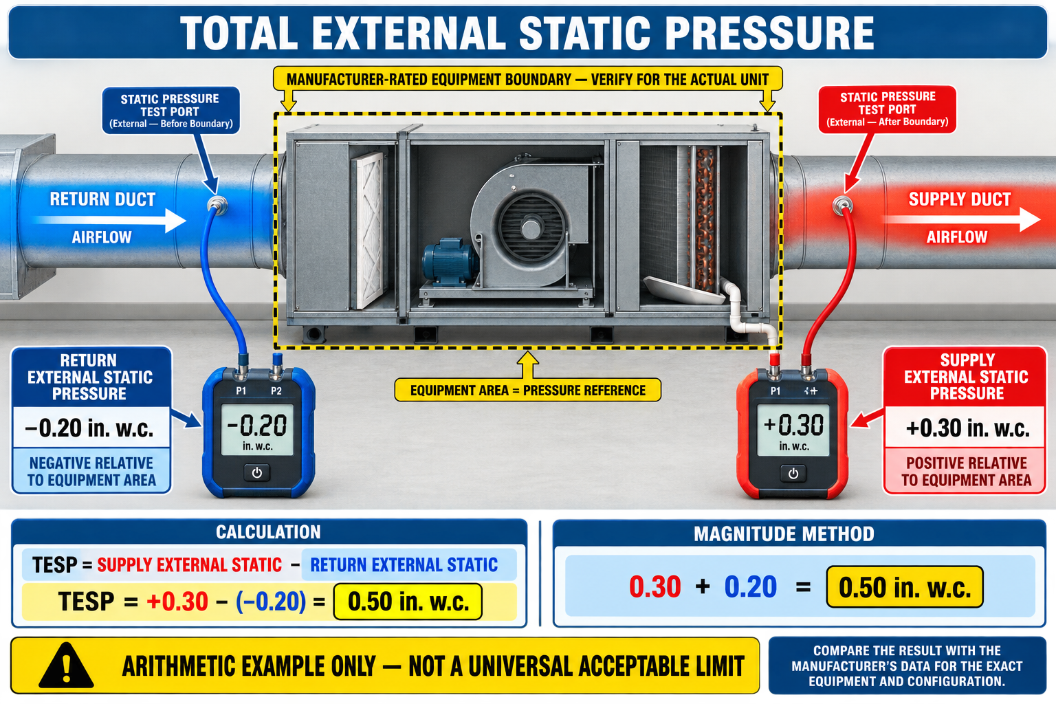
TESP = Supply SP − Return SP
Subtract the signed return pressure from the signed supply pressure. Subtracting a negative value increases the result.
TESP = |Supply SP| + |Return SP|
When supply is positive and return is negative relative to the same reference, add the absolute magnitudes of the two readings.
Measured supply static pressure is +0.31 in. w.c. and measured return static pressure is −0.24 in. w.c. Using signed values: +0.31 − (−0.24) = 0.55 in. w.c. Using magnitudes: 0.31 + 0.24 = 0.55 in. w.c.
The example demonstrates the calculation only. A TESP of 0.55 in. w.c. cannot be classified as acceptable or unacceptable until it is compared with the correct manufacturer’s maximum rating, blower table, measurement boundary, and required airflow for that specific equipment.
Keep the signed return and supply measurements in the service record. The calculated total alone hides how the resistance is divided and makes it harder to recognize whether the return side, supply side, or both require further testing.
External Depends on the Equipment Configuration
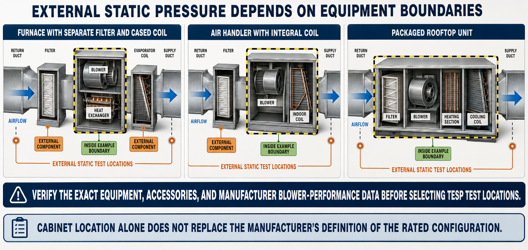
Furnace with Added Coil
A cooling coil installed in a separate casing above or downstream of a furnace is physically external to the furnace cabinet and may need to be included in the resistance compared with furnace blower data, depending on how that data is published.
Fan Coil or Air Handler
A coil, electric heat kit, or filter located inside a factory air-handler cabinet may already be included in or specifically accounted for by the manufacturer’s performance data.
Packaged Equipment
Factory filters, coils, heat exchangers, and blowers may all be inside the packaged-unit boundary, leaving the connected return and supply systems as the principal external resistance.
Field Accessories
External filters, air cleaners, humidifiers, dampers, sound attenuators, transitions, and field-installed coils consume available external static pressure unless the applicable data explicitly treats them differently.
Manufacturer tables may be labeled with filter, without filter, with a particular coil, without heater, or with other configuration notes. Read the table title, notes, footnotes, and installation instructions before using measured TESP to estimate airflow.
The Nameplate Limit Is Not a Universal Design Target
Many residential furnaces historically list a maximum external static pressure near 0.50 in. w.c., but that value is not universal. Other furnaces, air handlers, variable-speed units, small-duct systems, and commercial equipment can have different ratings. The correct value is the one published for the exact equipment and configuration.
An Operating Boundary
The maximum external static pressure identifies a limit associated with the equipment rating or permitted operation. It does not state that every system should be designed or adjusted to operate at that pressure.
Measured in the Field
The installed operating point is the combination of measured external static pressure and the active blower configuration. It should support required airflow without exceeding equipment limitations.
Nameplate
Look for maximum external static pressure and confirm whether the nameplate refers to the complete unit or a specific furnace, fan section, or air handler.
Installation Instructions
Use the current instructions for test locations, allowed orientations, filter provisions, heat kits, coil combinations, airflow setup, and operating restrictions.
Service Facts or Product Data
Locate the airflow or fan-performance table for the complete model number and identify all stated test conditions and included components.
Selected System Requirements
Confirm the cooling, heat-pump, gas-heating, electric-heating, ventilation, and continuous-fan airflow requirements rather than assuming one airflow applies to every mode.
A system can operate below the maximum external static rating and still have incorrect airflow because of the blower setting, motor or wheel condition, leakage, component configuration, control operation, or an error in the measurement boundary.
Pressure Becomes an Airflow Estimate Only Through Valid Data
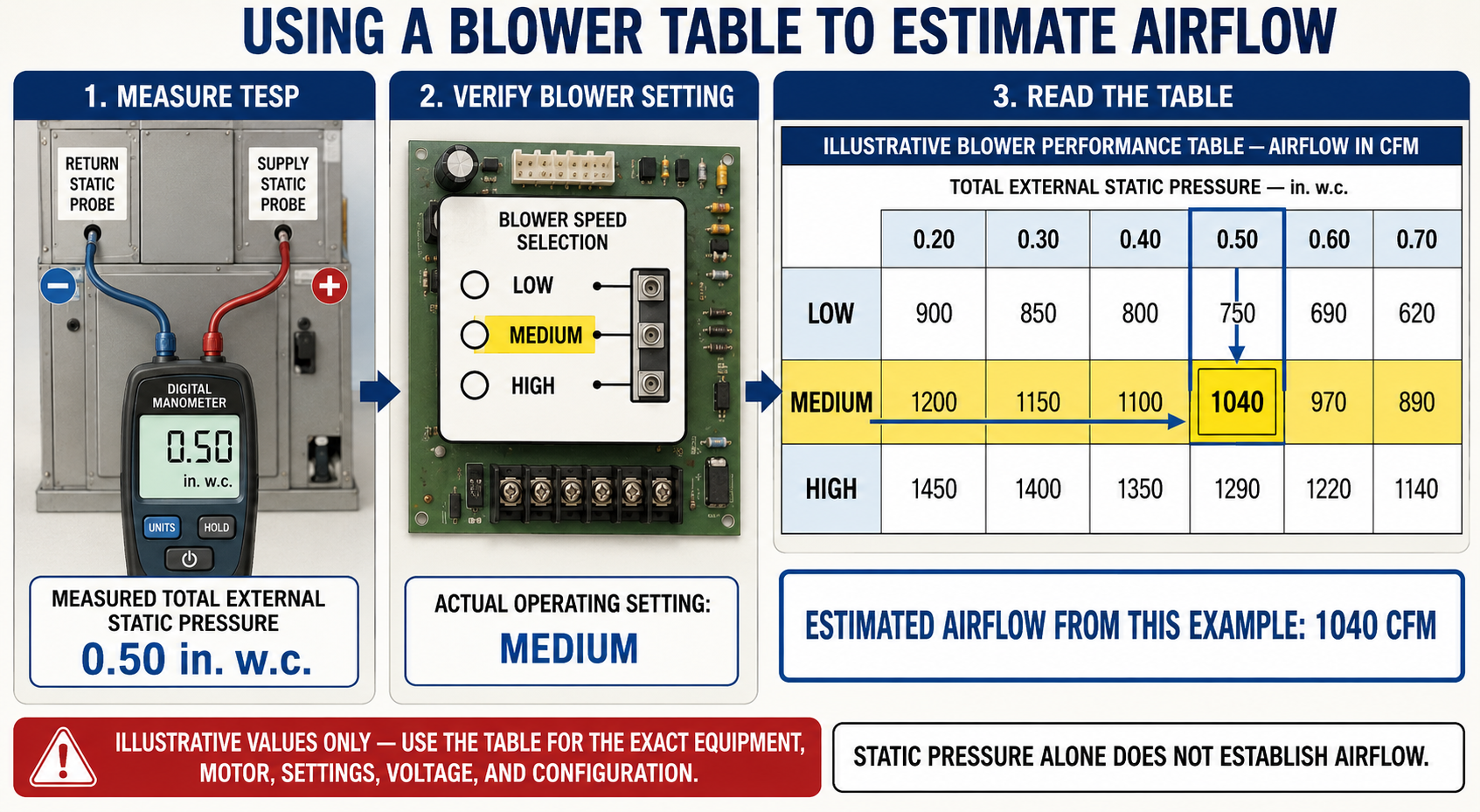
A blower table reports laboratory-tested or rated performance for specified equipment conditions. The technician uses the measured TESP to select the pressure column and the verified blower tap, speed, torque setting, airflow selection, or control configuration to select the correct row.
Exact Model
Match the complete furnace or air-handler model number, including cabinet or blower size. Similar-looking models can use different wheels, motors, controls, and tables.
Operating Mode
Heating, cooling, heat-pump heating, auxiliary heat, dehumidification, continuous fan, and staged operation may command different airflow settings.
Actual Configuration
Verify motor lead, speed tap, DIP switches, jumpers, control-menu settings, communicating controls, programmed tonnage, airflow adjustment, and active stage as applicable.
Table Conditions
Check whether values include a filter, coil, heat kit, wet-coil allowance, factory accessories, voltage condition, cabinet orientation, or other qualification.
Do not extend the table beyond its pressure range or assume performance between values unless the manufacturer permits interpolation. A dash, blank cell, restriction note, or maximum-airflow note may indicate an unapproved or unavailable operating point.
Different Blowers Respond Differently to Static Pressure
The relationship between airflow and external static pressure depends on the blower wheel, motor, and control strategy. This is why a generic fan curve or another model’s table cannot replace the data for the installed equipment.
PSC Blower
At a fixed speed tap, airflow normally decreases as external static pressure increases. Motor power behavior and airflow differ among taps, wheels, and furnace models.
Constant-Torque ECM
The motor applies programmed torque for the selected input but does not maintain identical CFM through every static-pressure condition. Use its specific performance table.
Constant-Airflow ECM
The control can increase motor speed and power to maintain selected airflow as resistance rises, but only within its programmed and mechanical operating limits.
Communicating System
Airflow may change with capacity stage, demand, humidity control, temperature limits, zoning, fault response, and control programming. Confirm the active command during measurement.
A variable-speed blower may maintain airflow by increasing speed and power, which can increase noise, energy use, and motor stress. Correct airflow at excessive static pressure does not eliminate the need to find and correct system resistance.
Estimate Blower Airflow Systematically
Verify the raw measurements.
Confirm signed supply and return static pressure, common reference, correct test ports, stable operation, and correct units.
Calculate TESP.
Subtract signed return pressure from signed supply pressure or add their absolute magnitudes under normal sign conditions.
Confirm the boundary.
Ensure the measured components match the definition and notes associated with the selected performance table.
Identify the active setting.
Verify the operating mode, stage, motor lead, tap, switches, jumpers, programmed airflow, and any airflow adjustment.
Select the table cell.
Use the correct row and pressure column, observing all notes, limitations, and permitted interpolation instructions.
Cross-check the estimate.
Compare the resulting CFM with required airflow, temperature performance, commissioning data, direct airflow measurements, and equipment operation.
Blower-table airflow assumes that the installed blower wheel, motor, voltage, controls, cabinet, and internal components perform like the published test configuration. Dirt, damage, incorrect rotation, voltage problems, control faults, and installation differences can cause actual airflow to differ.
High Resistance Requires More Measurements
TESP above the equipment’s permitted value indicates that the external air path is imposing more resistance than the rated operating condition allows. The total identifies a system-level problem but does not by itself locate the restriction.
High Return Magnitude
Investigate filter pressure drop, return grille and duct sizing, blocked grilles, restrictive transitions, collapsed flex duct, closed dampers, undersized return paths, and return-side obstructions.
High Supply Pressure
Investigate coil or heat-section pressure drop, closed or restricted dampers and registers, undersized supply ducts, poor fittings, compressed flex duct, zoning configuration, and supply-side obstructions.
Both Sides Elevated
The return and supply systems may both consume excessive pressure, or airflow may be higher than intended because of blower setup or control operation.
Operating-Mode Difference
Static pressure can change between cooling, heating, auxiliary heat, fan-only, and zone combinations because airflow commands and air paths change.
After identifying excessive TESP, measure pressure drops across filters, coils, heat exchangers, dampers, accessories, and duct sections. Lesson 10 develops this restriction-diagnosis process.
A Lower Number Is Not Automatically Better
Correct Low Resistance
A properly sized, well-installed duct system can operate at relatively low external static pressure while delivering required airflow.
Low Blower Output
An incorrect airflow setting, failed motor input, control limitation, wheel problem, low voltage, wrong rotation, or inactive stage can produce low airflow and low static pressure.
Leakage or Disconnection
A major open duct, missing panel, absent filter, disconnected branch, or severe cabinet leakage can reduce measured resistance while preventing proper air delivery.
Boundary or Port Error
Test points that omit external components, a probe affected by velocity, an unsealed panel, or an incorrect reference can produce an artificially low result.
Compare pressure with blower-table airflow, temperature change, delivered register airflow, equipment limits, motor operation, visual inspection, and the customer’s comfort complaint. Resolve inconsistent evidence before changing the system.
Avoid These TESP and Airflow Mistakes
Adding Signed Values Directly
Adding +0.31 and −0.24 produces +0.07, not TESP. Subtract the signed return value or add the two absolute magnitudes.
Calling TESP Total Pressure
TESP is an external static-pressure difference across equipment boundaries, not static pressure plus velocity pressure at one point.
Using 0.50 as a Universal Target
Maximum external static pressure varies by equipment. Even when 0.50 in. w.c. is the listed maximum, it is not automatically the desired design operating point.
Using the Wrong Table
A table for a similar model, different cabinet size, different motor, or different component configuration cannot establish airflow for the installed unit.
Ignoring Table Notes
Filter, coil, heat-kit, orientation, airflow, voltage, and operating limits in table notes can materially change which value applies.
Treating Estimated CFM as Directly Measured
TESP combined with blower data produces a model-based airflow estimate. Identify the method and confirm important results with other evidence.
Can You Connect TESP with Blower Airflow?
- What does each word in total external static pressure describe?
- How is TESP different from total pressure?
- If supply static pressure is +0.28 in. w.c. and return static pressure is −0.19 in. w.c., what is TESP?
- Why should the raw signed supply and return readings be retained?
- Why can a separately installed cooling coil be external to a furnace but internal to an air handler?
- Where should the maximum external static-pressure rating be found?
- Why is a listed maximum not automatically the desired system operating pressure?
- What equipment and control information must be verified before selecting a blower-table row?
- Why must the table title and footnotes be read?
- How does a PSC blower generally respond as external static pressure increases at a fixed tap?
- Why can a constant-airflow ECM make excessive resistance less obvious if only CFM is considered?
- Why can low TESP occur with poor airflow?
- What additional measurements help locate the cause of excessive TESP?
- Why should blower-table CFM be described as an estimate?
What You Should Have Learned
TESP is the static-pressure difference across the external air path defined for the equipment and manufacturer data being evaluated.
TESP equals positive supply static pressure minus signed negative return static pressure, or the sum of their absolute magnitudes under normal conditions.
External components and correct test locations depend on whether the system is a furnace with added components, an air handler, a fan coil, or packaged equipment.
The exact equipment nameplate and manufacturer literature determine maximum external static pressure; 0.50 in. w.c. is not a universal value or target.
Blower-table use requires the complete model, active mode and stage, actual motor or control setting, measured TESP, and all table qualifications.
PSC, constant-torque ECM, and constant-airflow ECM blowers respond differently as external static pressure changes.
High TESP identifies excessive system resistance but component and duct pressure drops are needed to locate the cause.
Low or apparently normal TESP does not prove correct airflow, and blower-table airflow remains an estimate that should agree with other diagnostic evidence.