Measuring Static Pressure Correctly
Static-pressure testing turns an invisible air-distribution condition into measurable evidence. A reliable reading depends on more than inserting a tube into a duct: the technician must define the measurement, select safe and representative test locations, prepare the instrument, orient the probe correctly, establish the proper reference, and document the operating condition.
This lesson presents a repeatable field procedure for measuring supply and return static pressure and pressure differences across components. Lesson 9 will use properly obtained readings to calculate total external static pressure and estimate blower airflow from manufacturer data.
What You Will Learn
By the end of this lesson you should be able to:
Define the measurement.
Identify the pressure, reference, equipment boundary, and diagnostic question before selecting test locations.
Select safe test ports.
Avoid hidden coils, heat exchangers, wiring, drain pans, refrigerant tubing, controls, and moving components.
Prepare the manometer.
Inspect the instrument, probes, and tubing; select the correct units; and zero the complete setup to the reference.
Place static probes correctly.
Position the sensing openings to minimize velocity-pressure influence and avoid turbulent or obstructed locations.
Obtain repeatable readings.
Control operating conditions, allow readings to stabilize, verify signs, and repeat questionable measurements.
Record useful results.
Document locations, units, signs, references, blower settings, filter condition, and equipment configuration.
What Pressure Are You Trying to Measure?
The correct test location depends on the question. A duct-to-room static-pressure reading, pressure drop across a filter, pressure drop across a coil, and total external static pressure are related measurements, but they do not use identical connections or necessarily use the same test ports.
Supply Static Pressure
Measure supply-duct static pressure relative to the selected ambient reference at a location suited to the diagnostic question.
Return Static Pressure
Measure return-duct static pressure relative to the same reference and expect a negative value during normal blower operation.
Component Pressure Drop
Measure static pressure immediately upstream and downstream of the component using locations that represent the air entering and leaving that component.
Equipment External Static
Measure at the boundaries defined for the equipment and manufacturer data being used. The included and excluded components depend on equipment configuration.
Identify the return grille, filter, blower, heat exchanger, auxiliary heat, evaporator coil, humidifier, dampers, supply plenum, and ducts in their actual installed order. Mark the proposed ports and confirm what lies between them.
Location Determines What the Reading Includes
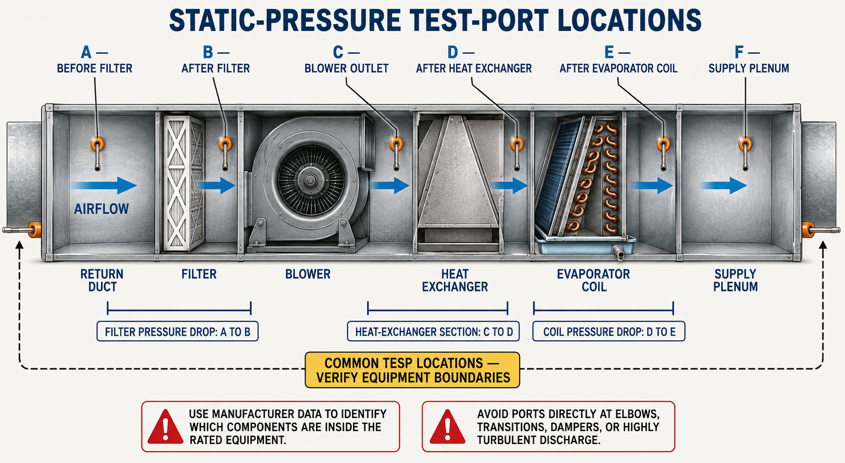
Static pressure changes throughout the air path. A port moved from one side of a filter, coil, heat exchanger, or cabinet transition to the other side can change the reading because another component has been added to or removed from the measured section.
Before and After a Filter
These ports allow direct measurement of filter pressure drop when both locations represent the airflow immediately entering and leaving the filter.
Before and After a Coil
These ports can show coil pressure drop, but drilling must never threaten the coil, refrigerant tubing, distributor tubes, drain pan, wiring, or cabinet seals.
Return Near Equipment
A return port used for external static pressure is normally placed in the external return air path near the equipment boundary, but not where the probe is dominated by turbulence or an obstruction.
Supply Near Equipment
A supply port must be located beyond the components intended to be inside the measurement boundary. Whether an external cooling coil is included depends on the equipment and data being evaluated.
Upflow, downflow, horizontal, fan-coil, heat-pump air-handler, furnace-and-coil, rooftop, and packaged systems place filters, blowers, coils, and heat sections differently. Follow the equipment manufacturer’s instructions and confirm the actual component arrangement.
Know What Is Behind the Surface
Inspect Both Sides
Open accessible panels, use drawings or manufacturer information, and inspect with a light or camera when possible before selecting the exact port location.
Control Electrical Energy
De-energize and lock out equipment when required for safe drilling or access. Restore power only after tools, debris, panels, and wiring are safely positioned for the operating test.
Limit Drill Penetration
Use an appropriate bit, depth stop, short bit, or guarded method to prevent the drill from reaching hidden components after it penetrates sheet metal.
Control Metal Shavings
Prevent shavings from entering electrical compartments, bearings, motors, burners, drain pans, coils, and occupied spaces, and remove debris before operation.
A misplaced bit can puncture a refrigerant circuit, damage a heat exchanger, contact energized wiring, penetrate a drain pan, or strike a moving blower. When a safe location cannot be confirmed, use an approved existing port or select another valid measurement method.
Establish a Controlled Operating Condition
A static-pressure reading belongs to the exact operating condition under which it was taken. Blower speed, equipment mode, filter condition, dampers, registers, zoning, doors, panels, and accessories can all change the result.
Confirm Operating Mode
Identify whether the equipment is in cooling, heating, auxiliary heat, continuous fan, dehumidification, or another mode and verify the active blower setting.
Inspect the Filter
Record the filter size, depth, type, MERV rating, orientation, fit, and condition. Do not silently substitute a clean filter unless the test purpose calls for that comparison.
Set Doors and Dampers
Place zone dampers, balancing dampers, registers, grilles, and interior doors in the condition required by the test, and record that condition.
Restore Panels
Install blower doors, filter covers, and access panels as they would be during normal operation unless the specified procedure requires otherwise.
If a complaint occurs only with certain zones active, doors closed, or a higher heating airflow operating, reproduce and document that condition instead of measuring only the easiest operating mode.
Inspect, Connect, and Zero Before Testing
Inspect the Manometer
Confirm battery condition, calibration status, suitable pressure range and resolution, intact ports, and the correct display units.
Inspect Probes and Tubing
Check for blocked sensing holes, damaged probes, splits, loose fittings, water, dirt, kinks, and pinched tubing that could prevent pressure transmission.
Connect Before Zeroing
Attach the tubing and probes in the configuration required by the instrument, expose both pressure inputs to the same ambient reference, and then zero the complete setup.
Verify the Unit
Confirm whether the display is in inches of water column or pascals and record the unit with every reading. Do not copy a number without its decimal place and unit.
Small sensor offsets can materially affect low-pressure readings. Remove both probes from the pressure sources, return them to the same reference, and verify zero before assuming an unexpected result is a system defect.
Sense Static Pressure, Not Impact Pressure
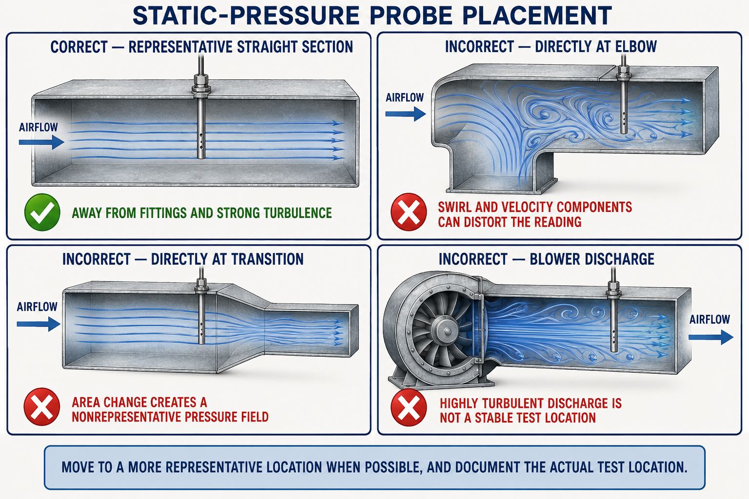
A static-pressure probe is shaped so its sensing openings do not face directly into the airflow. The probe must be inserted and oriented according to the probe manufacturer’s markings or instructions. A tube or opening pointed into the flow can sense part of the velocity pressure and produce a value that is not true static pressure.
Representative and Stable
Use a location away from immediate elbows, transitions, takeoffs, dampers, vanes, blower discharge, filter edges, coil faces, and other sources of strong turbulence when the installation permits.
Disturbed or Obstructed
A probe in a high-velocity jet, recirculation zone, wall boundary, fitting throat, or directly behind an obstruction may not represent average pressure at that section.
Insertion
Insert the probe far enough for its sensing openings to be fully exposed inside the air path and not buried in insulation, sealant, a liner, or the test-hole edge.
Orientation
Follow the probe’s airflow arrow or manufacturer instructions so the static openings remain perpendicular to the local airflow rather than facing into it.
Clearance
Keep the sensing area from touching the opposite duct wall, internal insulation, turning vanes, filters, coils, heat exchangers, or other internal surfaces.
Position Check
Gently rotate or reposition the probe when safe to do so. A large change can indicate excessive velocity influence, turbulence, or a nonrepresentative test point.
Measure Each Side Relative to the Same Reference
For separate duct-to-room readings, the reference side of the manometer remains open to the same room or ambient reference. Connect the static probe to the appropriate instrument port, insert it correctly, allow the reading to stabilize, and record both the sign and magnitude.
Normally Negative
Record the displayed negative value relative to the room, such as −0.24 in. w.c. Do not discard the sign merely because later calculations may use its magnitude.
Normally Positive
Record the displayed positive value relative to the same room, such as +0.31 in. w.c. Confirm an unexpected sign before proceeding.
These example values demonstrate recording format only and are not universal acceptable pressures. Proper interpretation requires the equipment manufacturer’s maximum external static pressure, blower-performance information, the defined measurement boundary, and the system’s intended airflow.
Record the actual signed supply and return readings before performing any addition or subtraction. Raw readings make it possible to verify calculations and recognize whether one side of the air path contributes disproportionately to the total.
Compare Immediately Upstream and Downstream
Pressure drop across a passive component is the decrease in static or total pressure attributable to that component under the test condition. For common service diagnostics, technicians often measure static pressure on both sides and calculate the difference using consistent locations and references.
Static-pressure difference most closely represents component resistance when the upstream and downstream test sections have comparable air velocity. Transitions, area changes, and strongly disturbed flow can convert static and velocity pressure, so use the component or equipment manufacturer’s specified test locations whenever they are available.
Direct Differential
Connect the higher-pressure side to the positive port and the lower-pressure side to the negative port so a dual-port manometer displays the drop directly.
Separate Readings
Measure both points relative to the same reference and calculate the algebraic difference. Preserve signs so return-side calculations are not accidentally reversed.
Filter Comparison
Compare the measured drop with appropriate filter data at the actual airflow and with a documented clean-filter baseline when available.
Coil or Heat Section
Compare the measured drop with manufacturer data or verified baseline information at the relevant airflow rather than relying on one generic limit.
A low component pressure drop can result from a clean, low-resistance component or from low airflow. A high drop can result from restriction or excessive airflow. Interpret pressure drop together with system airflow and operating condition.
Challenge the Reading Before Trusting It
Allow Stabilization
Wait for blower staging, dampers, refrigeration operation, and the pressure display to stabilize before recording a steady-state value.
Repeat the Measurement
Remove and reinstall the probe or repeat the reading after rechecking zero. Similar results increase confidence in the procedure.
Try a Nearby Valid Point
When turbulence is suspected, compare with another safe location in the same intended pressure zone. A large difference requires investigation.
Compare Related Readings
Supply, return, component, temperature, and airflow information should tell a physically consistent story. Resolve contradictions rather than choosing the preferred number.
Averaging several readings does not correct a fundamentally invalid test point. First confirm that each location measures the intended pressure under representative conditions.
Leave a Record and Seal the System
Record Equipment
Document model information, equipment arrangement, installed accessories, filter, blower setting, operating mode, and active zoning condition.
Record Each Port
Describe or photograph each location and identify whether it is upstream or downstream of specific components and inside or outside the defined equipment boundary.
Record the Result
Include the value, sign, unit, reference, instrument, and whether it was a direct static reading, differential reading, or calculated difference.
Seal and Restore
Remove probes, install suitable test-port plugs, restore insulation and vapor barriers, reinstall panels and covers, and confirm normal safe operation.
Properly located and sealed test ports allow future technicians to repeat measurements at the same locations, compare results with the baseline, and avoid unnecessary drilling.
Avoid These Static-Pressure Mistakes
Using Open Tubing as a Probe
An open tube aimed into airflow can sense impact pressure. A proper static probe provides more repeatable static-pressure measurements.
Drilling at a Convenient Spot
A convenient hole may be unsafe, turbulent, or on the wrong side of a component, causing the reading to answer a different question.
Zeroing with Pressure Applied
Zeroing while a probe senses duct pressure removes part or all of the actual pressure from the displayed result.
Dropping the Return Sign
Return static pressure is normally negative relative to the room. Preserve that sign in the raw reading and use the correct algebra for the intended calculation.
Testing with Panels Removed
An open blower door, filter cover, or cabinet panel can change the air path and invalidate a measurement intended to represent normal operation.
Applying a Universal Limit
Acceptable pressure depends on equipment specifications, airflow setting, component arrangement, and measurement boundary. Use the correct manufacturer data.
Can You Obtain a Reliable Static-Pressure Reading?
- Why should the air path and equipment boundary be identified before selecting test ports?
- Why is there no universal pair of test holes for every forced-air unit?
- What hidden components must be considered before drilling?
- Why should tubing and probes normally be connected before the manometer is zeroed?
- How should the static probe’s sensing openings be oriented relative to airflow?
- Why should test locations near elbows, dampers, transitions, and blower discharge be treated cautiously?
- What sign is normally expected for return static pressure relative to the room?
- What sign is normally expected for supply static pressure relative to the room?
- Why are example static-pressure values not universal acceptable limits?
- How can pressure drop across a filter be measured directly with a dual-port manometer?
- Why can a low component pressure drop indicate either low resistance or low airflow?
- What information should be recorded with every static-pressure measurement?
What You Should Have Learned
The diagnostic question and equipment boundary determine which test locations are valid and which components are included.
Test ports must be selected only after checking for hidden coils, heat exchangers, tubing, wiring, pans, controls, and moving parts.
The system must operate in a controlled and documented condition with normal panels, filters, dampers, and blower settings.
The manometer, probes, and tubing should be inspected, correctly connected, set to the intended units, and zeroed to a common reference.
A static probe must be properly inserted and oriented so its sensing openings are not exposed to direct impact pressure.
Return static is normally negative and supply static normally positive when both are measured relative to the same room reference.
Component pressure drop must be interpreted with airflow, manufacturer data, operating condition, and a valid clean baseline when available.
Repeatable measurements require suitable locations, zero verification, stabilized operation, preserved signs, complete documentation, and sealed ports.