Airflow and Duct-Pressure Measurement Tools
Duct-system diagnosis requires more than feeling air at a register or looking at a filter. Technicians need instruments that can measure the small pressure differences, air velocities, volume flow rates, and temperatures found in residential and light-commercial air systems.
This lesson introduces manometers, static-pressure probes, Pitot tubes, anemometers, flow hoods, temperature instruments, tubing, test ports, and filter-pressure gauges. The goal is to select the correct tool and understand what its reading represents; detailed static-pressure test locations and procedures are covered in the next lesson.
What You Will Learn
By the end of this lesson you should be able to:
Select a manometer.
Identify pressure range, resolution, accuracy, ports, units, and functions needed for duct-pressure work.
Match probes to pressure.
Distinguish static-pressure probes from Pitot tubes and explain what each senses.
Compare airflow instruments.
Choose among vane anemometers, hot-wire anemometers, Pitot traverses, and capture hoods.
Use temperature measurements.
Explain how properly placed temperature and humidity instruments support airflow and equipment diagnosis.
Evaluate filters.
Distinguish MERV particle-capture efficiency from filter pressure drop and recognize the value of a differential-pressure gauge.
Protect measurement quality.
Recognize how zeroing, tubing, probe placement, averaging, instrument limits, and documentation affect results.
Different Questions Require Different Instruments
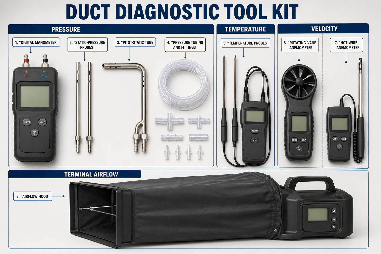
Pressure Question
Use a suitable manometer and the correct pressure pickup to measure static pressure, total pressure, velocity pressure, or pressure difference across a component.
Velocity Question
Use a Pitot tube with a sensitive manometer or an appropriate vane or thermal anemometer to measure air speed at defined locations.
Volume-Flow Question
Use a capture hood or determine average duct velocity across a representative traverse and multiply by the actual free duct area.
Heat-Transfer Question
Use appropriate temperature and humidity instruments with airflow information to evaluate the air side of cooling and heating equipment.
Do not begin with the instrument that is easiest to reach. Decide whether the needed result is pressure, pressure difference, velocity, CFM, temperature, humidity, or a combination, and then select the instrument and test method.
Measuring Small Pressure Differences
A manometer measures pressure or the difference between two pressures. HVAC duct pressures are small, so technicians commonly use a digital differential manometer that reads inches of water column and often pascals. An analog inclined manometer can also provide stable, visible readings when properly installed and leveled.
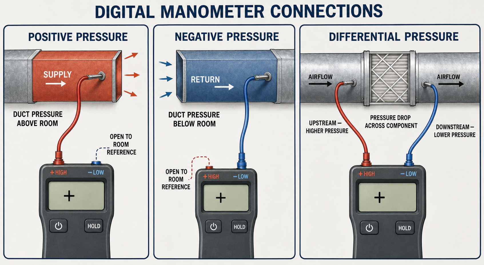
Single-Pressure Reading
One port senses the duct or room being tested while the reference port remains open to the selected reference, commonly the surrounding room.
Differential Reading
Both ports are connected so the instrument directly displays the pressure difference between two locations, such as opposite sides of a filter or coil.
Useful Features
Zeroing, selectable units, averaging, hold, minimum and maximum capture, wireless display, data logging, and separate probes can improve field efficiency when correctly used.
Instrument Selection
Choose a range that safely includes expected values while providing enough resolution and accuracy for low duct pressures. A combustion or refrigerant gauge is not automatically suitable for air-system static pressure.
A display may show pressure to the thousandth of an inch without being accurate to the thousandth. Read the instrument specifications for range, resolution, stated accuracy, operating limits, and required calibration.
The Pressure Pickup Is Part of the Measurement
Static-Pressure Probe
A static probe is designed to sense static pressure while minimizing the influence of air velocity. Its sensing openings are oriented so they do not face directly into the airflow.
Pitot-Static Tube
A Pitot-static tube has separate total-pressure and static-pressure connections. Their difference is velocity pressure, which can be used to calculate air velocity.
Flexible Tubing
Tubing must fit securely and remain open. Kinks, pinches, water, dirt, splits, loose fittings, reversed connections, and heat damage can alter or prevent pressure transmission.
Test Ports and Plugs
Test holes should be safely located, sized for the probe, and sealed with suitable plugs after testing. Never drill before checking for coils, heat exchangers, wiring, drain pans, controls, refrigerant tubing, or other hidden components.
De-energize equipment when drilling or when required by the task, inspect both sides whenever possible, control metal shavings, and keep hands, clothing, tubing, and probes away from blowers, belts, electrical parts, hot surfaces, and moving dampers.
Know What the Manometer Is Comparing
Static Pressure Relative to Ambient
One port senses duct static pressure and the other references the room. The reading may be positive on the supply side or negative on the return side.
Component Pressure Drop
One port connects upstream and the other downstream of the component. The differential shows the pressure consumed while air passes through it.
Velocity Pressure
A Pitot-static tube provides total and static pressure connections. Subtracting static pressure from total pressure produces velocity pressure.
Building Pressure
One connection references the room and the other references outdoors. Wind and tubing placement can strongly influence this small differential measurement.
Write down the locations connected to the positive and negative ports. A recorded number without connection locations, units, sign, and operating condition cannot be reliably interpreted later.
Velocity and CFM Require the Correct Method
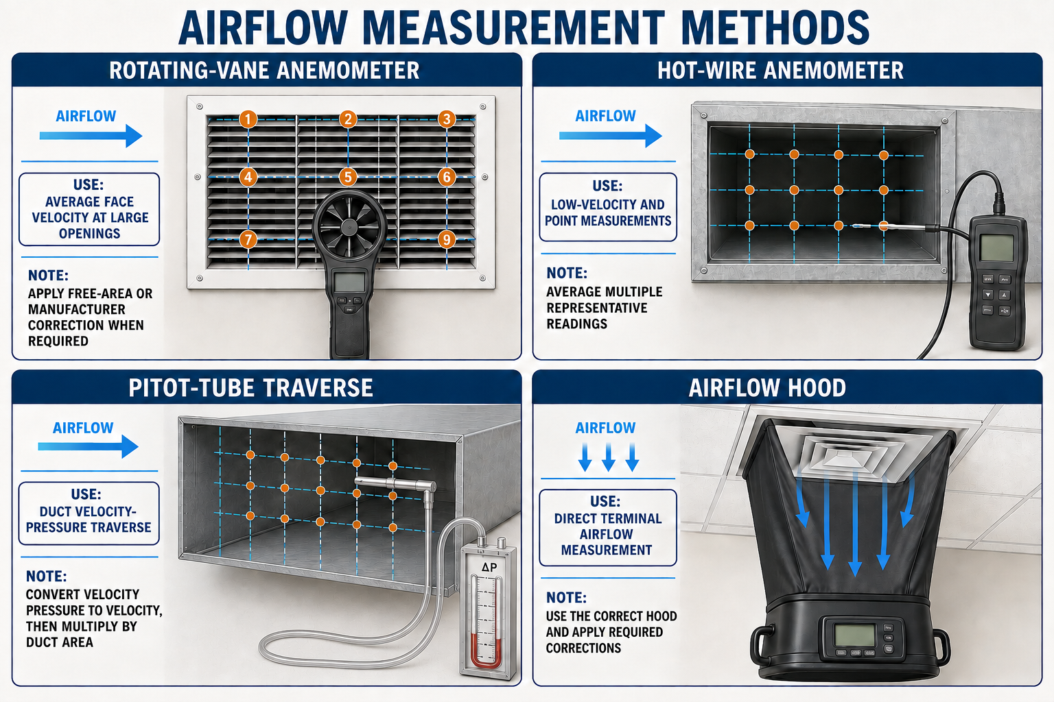
Rotating-Vane Anemometer
A vane anemometer measures air velocity over the area of its rotating vane. It is useful at many grilles and larger openings when the instrument, grille geometry, free area, averaging method, and flow direction are considered.
Hot-Wire Anemometer
A thermal or hot-wire anemometer is sensitive at lower velocities and can be used for duct traverses. Probe orientation, temperature limits, contamination, and uneven flow affect results.
Pitot-Tube Traverse
A Pitot tube and micromanometer determine velocity pressure at multiple points across a suitable duct section. Those readings are converted to velocity, averaged, and multiplied by actual duct area to determine airflow.
Airflow Capture Hood
A flow hood captures air at a supply or return opening and reports volume flow. The hood must fit and seal around the opening, be used in the correct flow direction, and be suitable for the diffuser and airflow range.
Air velocity is rarely uniform across a duct or grille. Reliable CFM normally requires a defined traverse or capture method, representative averaging, correct area, and any instrument or outlet correction required by the method.
Useful Estimates with Important Assumptions
Blower-Performance Data
Measured total external static pressure can be matched to the exact manufacturer’s blower table or fan data when the model, motor, wheel, speed or airflow setting, and equipment configuration are known.
Temperature-Based Methods
Airflow can sometimes be estimated from measured heat input or output and temperature change, but the method depends on correct inputs, steady operation, air properties, and whether sensible and latent heat are properly handled.
Fan-Powered Instruments
Powered flow devices can measure airflow through a grille or system while controlling test pressure, depending on the instrument and procedure. These are common in balancing and duct-leakage applications.
System Comparison
Repeatable baseline readings can reveal changes after service even when the method does not provide laboratory-grade absolute airflow, provided the test setup remains the same.
Blower-table and temperature-based airflow methods are valuable diagnostic tools, but their results inherit the uncertainty of every input and assumption. Document the method rather than reporting all CFM values as equally direct measurements.
Airflow Diagnosis Often Needs More Than Pressure
Temperature measurements help show whether air is exchanging heat with a coil or heat exchanger, while humidity measurements are important when cooling includes moisture removal. Instruments should have suitable range, accuracy, response time, and probe type for the application.
Dry-Bulb Temperature
Measure representative entering and leaving air, shield probes from radiant heat, avoid direct contact with metal surfaces unless measuring surface temperature, and allow readings to stabilize.
Humidity and Wet-Bulb
A psychrometer or accurate temperature-humidity instrument helps characterize entering and leaving air during cooling and dehumidification. Sensor condition and equilibration time matter.
Multiple Probes
Simultaneous or matched probes can reduce errors caused by changing operating conditions, but sensors should be checked against one another before relying on small temperature differences.
Air Mixing
Stratification, bypass air, outdoor-air entry, duct leakage, and poor mixing can make a single temperature point unrepresentative of the average airstream.
MERV Rating and Pressure Drop Describe Different Things
MERV means Minimum Efficiency Reporting Value. It is derived from the ASHRAE 52.2 test method and reports a filter’s ability to capture specified particle sizes from 0.3 to 10 micrometers. A higher MERV rating indicates better capture performance for the particle-size ranges represented by the rating; it is not a direct rating of airflow resistance.
Particle-Capture Performance
MERV describes filtration efficiency under a standardized test. It helps compare how filters remove particles, but it does not by itself tell the technician the installed pressure drop.
Resistance at an Airflow
Filter pressure drop is the difference between pressure upstream and downstream of the filter at the operating airflow. It changes with filter design, face area, depth, media, installation, airflow, and dust loading.
Two filters with the same MERV rating can have different pressure drops, and a well-designed deeper filter can provide higher particle efficiency without the pressure penalty of a smaller filter with less media area. Before upgrading filtration, compare the filter manufacturer’s pressure-drop data at the expected airflow and confirm that the blower and filter rack can accommodate the selected filter.
Portable Manometer
Temporary probes on both sides of the filter allow the technician to measure filter pressure drop during diagnosis and compare it with appropriate clean-filter or manufacturer data.
Installed Differential Gauge
A permanently installed differential-pressure gauge or switch can indicate filter loading based on actual resistance rather than calendar time alone when the system operates at a consistent airflow.
Clean Baseline
Record pressure drop after installing the correct clean filter at a documented operating condition. That baseline supports meaningful future comparisons.
Replacement Limit
Use filter, equipment, or design information to establish an acceptable final pressure drop. Do not invent one universal replacement value for every filter and system.
Select the needed filtration efficiency while preserving required system airflow. Filter dimensions, depth, surface area, published resistance, rack leakage, equipment capability, and maintenance access are all part of the decision.
Good Tools Still Require Good Technique
Inspect and Zero
Inspect probes and tubing, connect them as required by the instrument, place both pressure inputs at the same reference, and zero the manometer according to its instructions before testing.
Stay Within Limits
Do not exceed pressure, velocity, temperature, humidity, or environmental limits. Protect sensors from water, dust, impact, and temperatures outside their ratings.
Choose Representative Locations
Avoid turbulence near elbows, dampers, transitions, takeoffs, fans, and obstructions when the procedure calls for developed flow. Use multiple points when the airstream is not uniform.
Document Conditions
Record units, sign, locations, reference, equipment model, blower setting, filter, damper and door positions, operating mode, and whether the reading was direct, calculated, or estimated.
Use the same locations, instruments, setup, and operating conditions before and after a repair. A repeatable comparison can demonstrate improvement and expose inconsistent readings that need investigation.
Avoid These Measurement Mistakes
Wrong Probe for the Quantity
Open tubing facing into the airstream does not provide the same measurement as a properly oriented static-pressure probe.
Reversed Connections
Swapping positive and negative ports reverses the displayed sign and can lead to an incorrect pressure-drop or duct-pressure conclusion.
No Zero Check
Sensor offset can be a significant portion of a small duct-pressure reading. Zero the instrument in the required configuration and recheck when readings appear questionable.
Single-Point Air Velocity
Using one convenient velocity reading as the average for an entire duct or grille can produce a large airflow error.
Ignoring Tool Influence
A hood, probe, tubing run, or inserted instrument can alter the airflow being measured. Use the tool and correction method intended for the application.
Missing Test Conditions
A pressure or CFM value without the blower setting, equipment mode, filter condition, and measurement locations may not be reproducible or useful.
Can You Select the Correct Measurement Tool?
- What does a differential manometer compare?
- Why are pressure range, resolution, and accuracy all important when selecting a duct manometer?
- How does a static-pressure probe differ from a Pitot-static tube?
- What can happen if pressure tubing is kinked, wet, split, or loosely connected?
- Which instrument directly captures volume flow at a supply or return opening?
- Why is a single velocity reading usually insufficient to determine duct CFM?
- What additional information is needed to use a manufacturer’s blower-performance table?
- What does MERV report?
- Does a MERV rating directly state filter pressure drop?
- Why should filter pressure drop be evaluated at the system’s operating airflow?
- What should be checked before drilling a duct or equipment test port?
- What operating information should accompany a recorded airflow or pressure measurement?
What You Should Have Learned
A manometer measures pressure or pressure difference, and its range, resolution, accuracy, units, and port arrangement must suit the task.
Static probes sense static pressure, while Pitot-static tubes provide total and static pressure for determining velocity pressure.
Vane anemometers, hot-wire anemometers, Pitot traverses, and flow hoods serve different airflow-measurement applications.
Reliable CFM requires a representative measurement method, averaging where necessary, correct area, and appropriate instrument corrections.
Temperature and humidity instruments support air-side diagnosis when sensors are accurate, stabilized, and placed in representative airstreams.
MERV describes particle-capture performance, while filter pressure drop describes airflow resistance at a particular operating condition.
Tubing condition, probe orientation, zeroing, measurement location, and instrument limits directly affect reading quality.
Every result should be documented with its units, sign, locations, reference, equipment setup, operating condition, and measurement method.