Duct Leakage, Insulation, and Condensation
Duct leakage changes more than the amount of air reaching a register. Supply leaks can lose conditioned air and alter building pressure, while return leaks can draw hot, cold, humid, dusty, or contaminated air into the system. Missing insulation, compressed insulation, open seams in the vapor-retarder jacket, air leaks, high surrounding dew point, and low duct-surface temperature can then combine to produce condensation.
This technician-focused lesson explains how leakage location and duct pressure determine the system effect, where ducts commonly leak, how to inspect and seal different connections, how insulation and vapor control limit heat transfer and moisture problems, and how total-duct-leakage and leakage-to-outside tests answer different questions. It builds on the terminal and return-path relationships from Lesson 14.
What You Will Learn
By the end of this lesson you should be able to:
Explain supply and return leakage.
Predict how leakage changes delivered airflow, equipment airflow, building pressure, energy use, comfort, moisture, and indoor air quality.
Locate common leakage sites.
Inspect equipment cabinets, plenums, seams, takeoffs, fittings, flex collars, boots, filter racks, access panels, dampers, and disconnected ducts.
Select appropriate sealing methods.
Match mechanical fastening, mastic, reinforcing mesh, gaskets, listed tape systems, and other approved materials to the duct construction and joint.
Evaluate duct insulation.
Recognize how insulation continuity, R-value, compression, thermal bridges, and installation location affect heat gain, heat loss, and surface temperature.
Diagnose condensation.
Connect surface temperature, surrounding-air dew point, insulation, vapor-retarder condition, air leakage, and system airflow before making repairs.
Interpret duct-leakage tests.
Distinguish total leakage from leakage to outside and recognize what a test result does and does not prove about normal system operation.
The Same Opening Can Have Different Effects
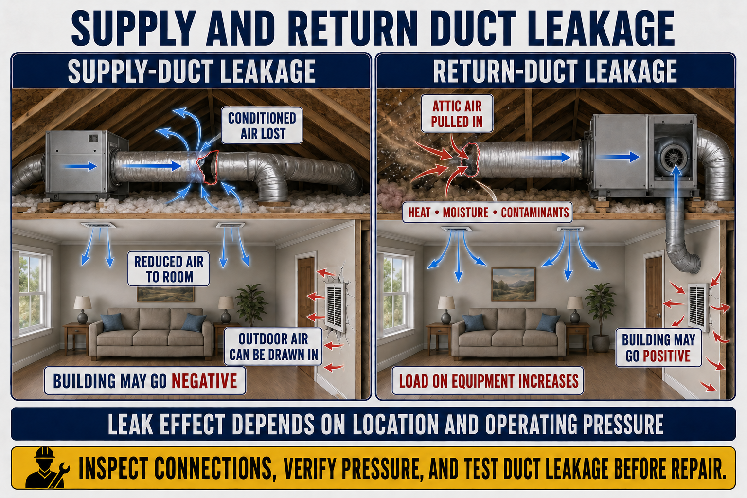
Leakage airflow depends on the size and shape of the opening and the pressure difference across it. A small opening near the equipment, where duct pressure is often greatest, can move more air than a similar opening near a low-pressure terminal. System mode, blower setting, filter loading, damper position, and zone configuration can change the pressure and therefore the leakage.
Supply Leakage
Positive duct pressure pushes conditioned air through openings. Leakage outside the conditioned enclosure reduces useful delivery and can make the building negative relative to outdoors.
Return Leakage
Negative return pressure draws surrounding air into the system. A leak in an attic, crawlspace, garage, or equipment closet can introduce heat, cold, humidity, dust, odors, or contaminants.
Leakage Inside
Leakage within the conditioned and pressure enclosure may have a smaller direct energy penalty, but it can still disturb room delivery, filtration, equipment airflow, pressure balance, comfort, and sound.
Disconnected Duct
A disconnected branch or return is not a minor seam leak. It can dominate system performance and should be found before attention shifts to small accessible joints.
The same measured airflow can have very different consequences depending on whether it is supply or return leakage and whether it connects the duct system with conditioned space, outdoors, an attic, crawlspace, garage, wall cavity, or another pressure zone.
Duct Leakage Can Move Air Through the Building Enclosure
Supply Leakage Outside
If return airflow is drawn from the house but part of the supply escapes outside the enclosure, the house can become negative and draw outdoor or adjacent-zone air inward through enclosure leaks.
Return Leakage Outside
If the return draws additional air from outside the enclosure and the supply delivers it indoors, the house can become positive and push indoor air outward through enclosure leaks.
Unbalanced Leakage
Supply and return leakage rarely cancel perfectly. Their location, operating pressure, and airflow differ, so equal-looking holes do not imply a pressure-neutral building.
Closed Rooms
Inadequate return paths can pressurize supplied rooms and depressurize common areas even when the duct system itself is tight. Separate room-pressure diagnosis from duct-leakage diagnosis.
Return leakage or building depressurization can interact with atmospherically vented combustion equipment, garages, crawlspaces, attics, fireplaces, exhaust appliances, and soil gases. Follow applicable combustion-safety procedures and do not operate equipment in an unsafe condition.
Inspect the Complete Air Path
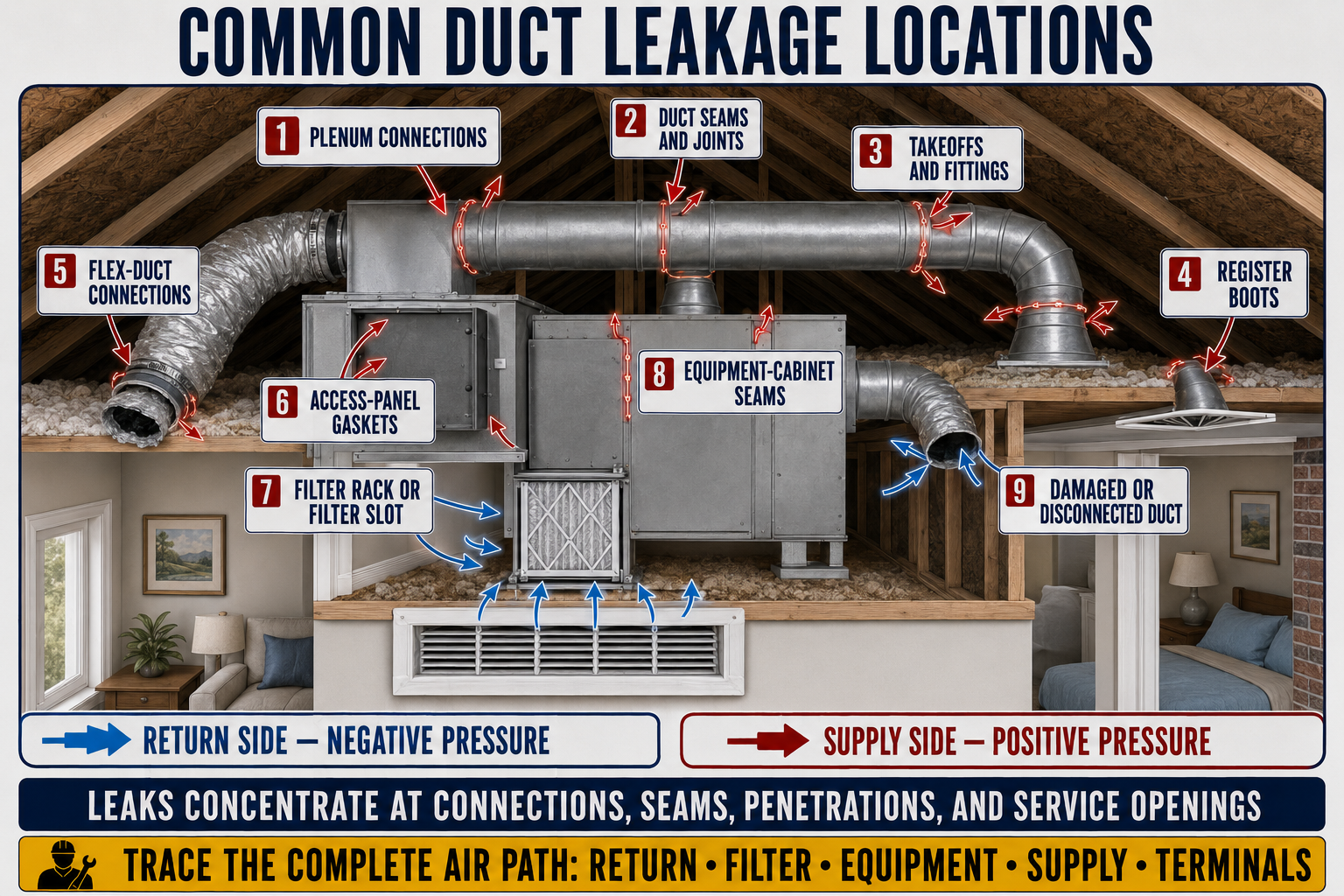
Equipment and Plenums
Inspect cabinet-to-coil, cabinet-to-plenum, filter-rack, access-panel, wiring, piping, drain, and service penetrations without sealing openings required for safety, drainage, combustion, or service.
Trunks and Fittings
Check longitudinal seams, transverse joints, end caps, drives, slips, elbows, transitions, branch taps, dampers, and field-fabricated corners.
Flexible-Duct Collars
Confirm that the inner liner is attached, mechanically secured, and sealed to the collar. An intact outer jacket can hide a disconnected or leaking inner liner.
Boots and Building Surfaces
Inspect the duct-to-boot joint and the boot-to-drywall, subfloor, or finished-surface joint. Each can connect the system with a wall, floor, attic, or crawlspace cavity.
Duct Board
Check fabricated corners, stapled closures, takeoff penetrations, damaged facing, access openings, and connections to metal fittings using methods approved for the product.
Hidden Cavities
Panned joists, wall cavities, platform returns, chases, and building cavities may leak along their entire construction rather than at one obvious duct joint.
Begin with disconnected ducts, large openings, equipment and plenum leaks, high-pressure supply joints, high-negative-pressure return openings, and leaks connected to unconditioned or contaminated spaces. Do not spend the entire repair budget coating low-impact seams while a major defect remains.
Use More Than One Type of Evidence
Visual and Physical Inspection
Look for disconnected sections, failed tape, gaps, dust streaks, disturbed insulation, loose collars, damaged boots, staining, wet materials, and movement while the blower operates.
Air-Movement Indicators
Smoke or another approved visible-air method can reveal leakage direction when used safely around moving equipment, smoke detectors, occupants, combustion appliances, and sensitive materials.
Pressure Measurements
Static-pressure profiling can identify a restricted or disconnected section, but ordinary operating-pressure readings do not quantify total duct leakage.
Thermal Inspection
Infrared patterns can help locate thermal anomalies, missing insulation, or leakage when temperature differences are favorable, but surface patterns require confirmation.
Flow Comparison
Comparing equipment airflow with measured terminal delivery may suggest leakage or measurement error, but losses, instrument limitations, and inaccessible returns must be considered.
Duct Pressurization
A calibrated duct tester provides a repeatable leakage measurement at a defined test pressure after the system is isolated according to the selected standard or program procedure.
Secure the Joint, Seal the Air Boundary, and Restore the Thermal Boundary
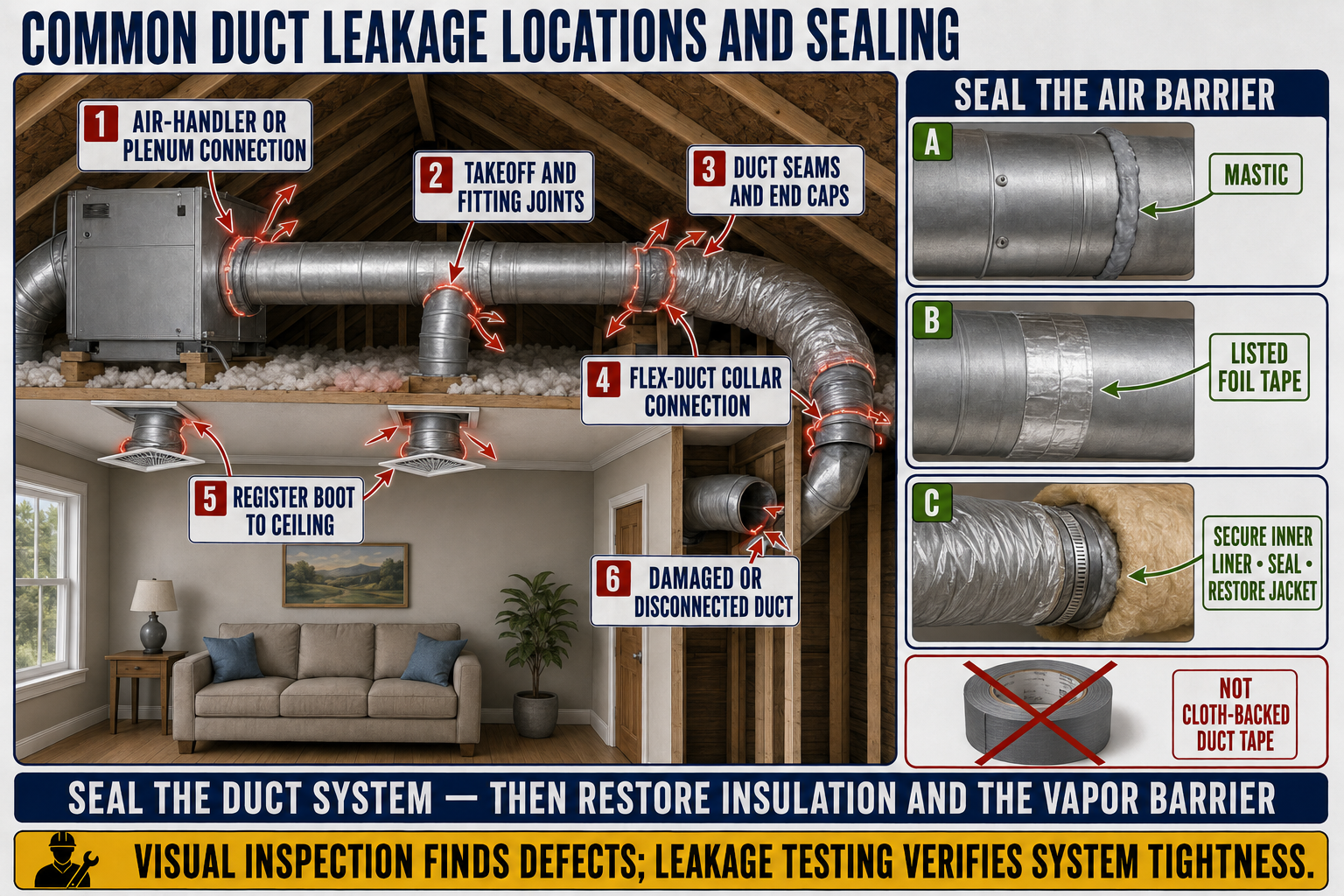
Expose and clean the joint.
Remove loose failed material and prepare dry, sound surfaces as required by the sealant or tape manufacturer without damaging the duct or releasing hazardous material.
Repair the structure.
Reconnect separated ducts, reshape damaged metal, replace failed collars or panels, and install required mechanical fasteners before expecting sealant to hold the assembly together.
Seal the air boundary.
Apply compatible listed mastic, reinforcing mesh where required, UL 181 tape systems, gaskets, aerosol sealant, or another approved material according to its listing and instructions.
Seal boots to surfaces.
Seal the boot or register box to the finished air-barrier surface with an approved compatible material so wall, floor, and ceiling cavities are not connected to the duct opening.
Restore insulation and jacket.
Replace missing insulation, avoid compression and gaps, and close the vapor-retarder jacket using a method compatible with the insulation system.
Verify the repair.
Inspect after curing, repeat the leakage test or relevant operating measurements, and confirm that service panels, drains, dampers, access, and safety functions remain usable.
Use materials listed and approved for the specific duct application. Pressure-sensitive tape must have the correct UL 181 classification and be installed on compatible prepared surfaces according to the product instructions.
Mastic and tape seal air; they should not be expected to carry the weight of a disconnected duct, replace required fasteners, correct a crushed fitting, or support a sagging flexible run.
Limit Heat Transfer and Keep Surfaces Above Dew Point
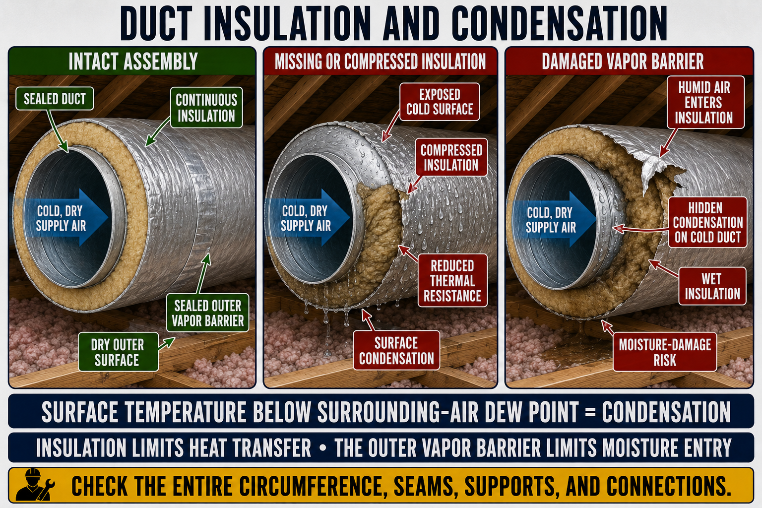
Duct insulation slows heat transfer; it does not stop it completely. Cooling ducts in hot spaces gain heat and can deliver warmer air, while heating ducts in cold spaces lose heat and can deliver cooler air. These losses change equipment runtime, room delivery, and the temperature difference available at the terminal.
R-Value
Thermal resistance depends on the insulation material, installed thickness, density, temperature, and condition. Follow the applicable code and product listing for the required installation.
Compression
Crushed insulation loses thickness and therefore thermal resistance. Narrow hanging straps, tight wire ties, framing contact, and overwrapped joints can create local cold spots.
Gaps
Exposed metal at seams, elbows, boots, collars, dampers, hangers, and equipment transitions can fall below the surrounding-air dew point even when nearby duct surfaces remain dry.
Wet Insulation
Wet insulation performs poorly and may conceal corrosion, biological growth, or continuing water entry. Find the moisture source before replacing or covering the material.
Internal Liner
Internal insulation may provide thermal and sound control, but damaged or contaminated material requires evaluation under manufacturer, code, and indoor-air-quality requirements.
Location
Ducts outside the building’s thermal enclosure face more severe temperatures and humidity. Duct location is part of the design, not merely an insulation-detail decision.
Keep Humid Air Away from Cold Surfaces
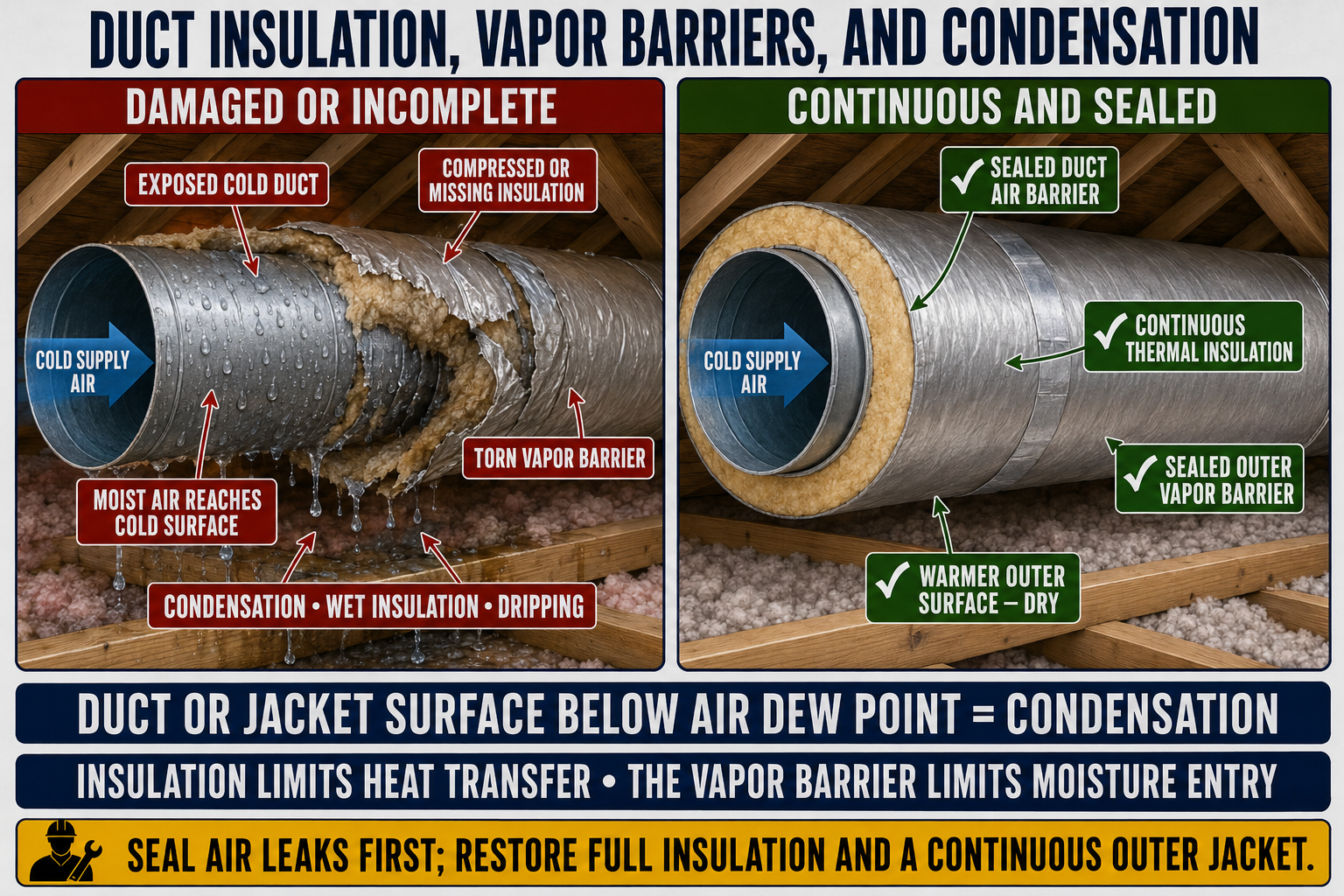
Air Boundary
The duct wall and sealed joints contain the HVAC airstream. Supply leakage can cool nearby surfaces, while return leakage can pull humid surrounding air into the system.
Thermal Boundary
Insulation reduces heat flow and keeps the jacket surface closer to the surrounding temperature. Continuity is especially important at joints, supports, boots, and transitions.
Vapor Retarder
The exterior jacket of a cooling-duct insulation system limits water-vapor movement toward colder material. Open laps, tears, punctures, and poorly sealed terminations can defeat this function.
Surrounding Dew Point
Condensation becomes possible when a surface is at or below the dew-point temperature of the air contacting it. High attic, crawlspace, or indoor humidity increases the risk.
Bulk airflow through an opening can transport moisture rapidly, while vapor diffusion moves moisture through materials because of vapor-pressure difference. A successful repair maintains the duct air seal, insulation, and vapor-retarder continuity.
Find Why the Surface Is Wet Before Adding Insulation
Surface Temperature ≤ Surrounding-Air Dew Point
Water forms only when moisture reaches a surface cold enough for the surrounding air condition. Both sides of that relationship must be investigated.
Why Is the Surface Cold—or the Dew Point High?
Measure air temperature, relative humidity, dew point, duct surface temperature, system airflow, and operating conditions instead of diagnosing from water location alone.
Missing or Compressed Insulation
A local thin area or thermal bridge can drop the jacket temperature below dew point while the remainder of the duct stays dry.
Damaged Vapor Retarder
Humid air can reach colder insulation or duct surfaces through open seams, torn jacket, unsealed penetrations, and incomplete terminations.
High Ambient Dew Point
Moisture entry, poor ventilation control, crawlspace or attic conditions, open access panels, or building-pressure problems can raise the air dew point around the duct.
Low Supply-Air Temperature
Low airflow, control problems, abnormal refrigeration operation, or an unusually low temperature setting can make duct surfaces colder and may also endanger equipment.
Supply Air Leakage
Cold air escaping at a joint can chill metal, the outer jacket, adjacent framing, or nearby piping and create condensation away from the apparent duct opening.
Water from Another Source
Roof leaks, plumbing, drain-pan overflow, trapped condensate, humidifier leakage, and sweating refrigerant piping can wet duct insulation. Confirm the source before opening or replacing the duct.
Repair the moisture source, determine whether insulation or duct material can be safely dried or must be replaced, restore the air and vapor boundaries, and verify performance during representative cooling and humidity conditions.
Total Leakage and Leakage to Outside Answer Different Questions
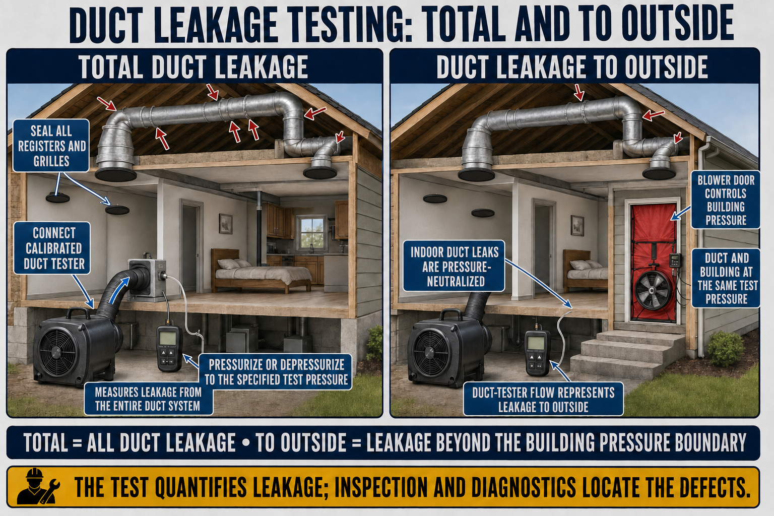
Total Duct Leakage
The registers and grilles are temporarily sealed and a calibrated fan measures airflow required to hold the duct system at the specified test pressure. Leakage both inside and outside the enclosure contributes to the result.
Leakage to Outside
The test procedure separates leakage connected to outdoors or spaces outside the building pressure enclosure. It normally requires coordinated duct and building pressure measurements.
Rough-In Test
Testing before finishes can expose the system for repair, but the equipment, boots, terminal connections, and final closures may not all be present. Apply the correct rough-in protocol and limit.
Final Test
A final test evaluates the completed system configuration, including the portions required by the selected standard, code, program, or specification.
CFM25
Residential leakage is commonly reported as cubic feet per minute at a test pressure of 25 Pa, but the allowable result and normalization method depend on the adopted code, program, construction stage, and test standard.
Operational Leakage
A laboratory-style leakage result at a fixed pressure does not equal the exact leakage during normal blower operation because operating pressures vary throughout the supply and return system.
Document which air handler, cabinet sections, plenums, returns, supply ducts, terminals, and zones were included; how openings were sealed; the test pressure; the test type; the standard used; and whether the reading was corrected or normalized.
A Number Without a Procedure Is Not Comparable
Select the governing procedure.
Identify the adopted code, energy program, commissioning specification, or diagnostic objective before choosing the test setup, pressure, normalization, and acceptance limit.
Define the enclosure and ducts.
Determine which ducts and equipment are inside or outside the conditioned and pressure enclosure and which system portions belong in the test boundary.
Configure the system safely.
Disable normal HVAC operation, open or position zone dampers as required, remove or isolate filters according to the procedure, and protect equipment from test pressure or debris.
Seal intentional openings.
Temporarily seal registers and grilles with materials that remain secure at test pressure without damaging finishes, then inspect each closure during the test.
Measure and record.
Use calibrated equipment, establish the required duct and building pressures, account for baseline pressure where required, and record the complete configuration.
Locate and repair.
Use the result with inspection and leakage-location methods, complete prioritized repairs, allow materials to cure, and repeat the same test for a valid before-and-after comparison.
Code editions, jurisdictions, ENERGY STAR requirements, weatherization programs, test stages, system locations, and normalization rules differ. Verify the currently applicable requirement rather than copying a limit from another project.
Connect Leakage, Insulation, Moisture, and Airflow Evidence
Define the symptom and mode.
Record whether the concern is low airflow, temperature loss, high humidity, odor, dust, noise, staining, water, energy use, or a failed leakage test and when it occurs.
Map duct location and pressure.
Identify which sections are supply or return, their operating pressure, their location relative to the building enclosure, and nearby moisture or contaminant sources.
Inspect air and thermal boundaries.
Trace joints, cabinets, boots, insulation, supports, jacket seams, penetrations, wet areas, and hidden cavities while respecting electrical, structural, respiratory, and fall hazards.
Measure operating performance.
Check TESP, blower airflow, component pressure drops, delivered airflow, temperature change, room pressure, ambient dew point, and duct-surface temperature as the complaint requires.
Perform the appropriate leakage test.
Use total leakage, leakage to outside, zonal pressure, pressure-pan, or another established diagnostic procedure only when it answers the defined question.
Repair and verify the system.
Correct prioritized defects, restore insulation and vapor control, repeat original measurements, and verify safe equipment operation and room delivery in the final configuration.
Avoid Repairs That Hide the Cause
Sealing Only Visible Seams
Accessible seams may be minor compared with disconnected branches, leaky plenums, cabinet openings, boot cavities, platform returns, or buried connections.
Using Tape as Structure
Tape cannot replace required mechanical fastening or support. Movement and duct weight can reopen a joint even when the original surface bond appeared sound.
Insulating Before Sealing
Covering an air leak makes it harder to locate and can direct cold air or moisture into insulation. Establish the air boundary before restoring the thermal and vapor layers.
Wrapping Over Wet Insulation
New jacket material can trap moisture and conceal continuing leakage, corrosion, or contamination. Find the source and assess damaged materials first.
Equating Total Leakage with Outside Leakage
Total leakage includes all measured duct leakage; it does not identify how much crosses the building enclosure or where each opening is located.
Ignoring Post-Repair Airflow
Sealing changes system resistance, building pressure, and airflow distribution. Recheck TESP, blower airflow, equipment temperatures, terminals, and room balance after substantial work.
Can You Diagnose Leakage, Insulation, and Condensation?
- Why does supply duct leakage normally flow outward?
- Why can return leakage in an attic or crawlspace be especially harmful?
- How can supply leakage outside the enclosure change building pressure?
- Why can two openings of the same size leak different amounts of air?
- Which equipment and duct connections should be included in a complete leakage inspection?
- Why must a separated joint be mechanically secured before it is sealed?
- What is wrong with using ordinary cloth-backed duct tape as the primary permanent seal?
- How do compressed insulation and exposed metal increase condensation risk?
- What function does the exterior vapor-retarder jacket perform on a cold duct?
- What two temperatures must be compared when diagnosing surface condensation?
- Why should wet insulation not simply be covered with new jacket material?
- What does a total-duct-leakage test include?
- How does a leakage-to-outside test differ from a total-leakage test?
- Why must system airflow and pressure be rechecked after significant duct sealing?
What You Should Have Learned
Supply ducts normally leak outward and return ducts normally leak inward because of their pressure relative to the surrounding space.
Leakage effect depends on opening size, pressure, supply or return location, and whether the leak connects with conditioned, unconditioned, outdoor, or contaminated space.
Complete inspection includes equipment cabinets, plenums, seams, fittings, takeoffs, flex collars, boots, filter racks, access panels, and hidden building-cavity returns.
Durable repair combines structural connection, approved sealing materials, restored insulation, and continuous vapor control rather than expecting one layer to perform every function.
Insulation reduces heat transfer and keeps cold-duct exterior surfaces warmer, while compression, gaps, wet material, and thermal bridges reduce its effectiveness.
Condensation becomes possible when moisture reaches a surface at or below the surrounding-air dew point, so both temperature and moisture conditions must be diagnosed.
Total duct leakage includes leakage wherever it goes, while leakage to outside isolates the portion connected beyond the building’s conditioned and pressure enclosure.
A valid repair is confirmed by repeating the applicable leakage, pressure, airflow, temperature, moisture, and room-delivery measurements under comparable conditions.