Registers, Grilles, Diffusers, Returns, and Balancing
A duct system does not succeed merely because the blower moves the correct total airflow. Supply air must leave each terminal with a pattern, velocity, temperature, and sound level that serve the room, while an adequate return path allows the same air to travel back to the equipment. Doors, furnishings, terminal selection, damper position, and room pressure can determine whether the occupants experience comfort or complaints.
This technician-focused lesson explains the differences among registers, grilles, diffusers, and return inlets; the concepts of throw, spread, drop, terminal velocity, pressure drop, and free area; the importance of closed-room return paths; and a measurement-based balancing process. It continues the fitting and effective-length discussion from Lesson 13.
What You Will Learn
By the end of this lesson you should be able to:
Identify common air terminals.
Distinguish registers, grilles, diffusers, and return inlets by their construction and intended function.
Explain supply-air patterns.
Describe throw, spread, drop, terminal velocity, entrainment, and how outlet location affects room air distribution.
Evaluate return-air paths.
Recognize the differences among central returns, dedicated returns, transfer grilles, jump ducts, and incidental door openings.
Measure closed-room pressure.
Use a sensitive manometer to compare a closed room with the main body of the building under a defined blower condition.
Balance delivered airflow.
Measure supply and return performance, adjust the intended balancing devices, and recheck interacting branches.
Verify the complete system.
Confirm blower operation, TESP, temperatures, room airflow, pressure balance, terminal sound, and final damper positions after adjustment.
The Last Component Shapes the Air Entering the Room
Register
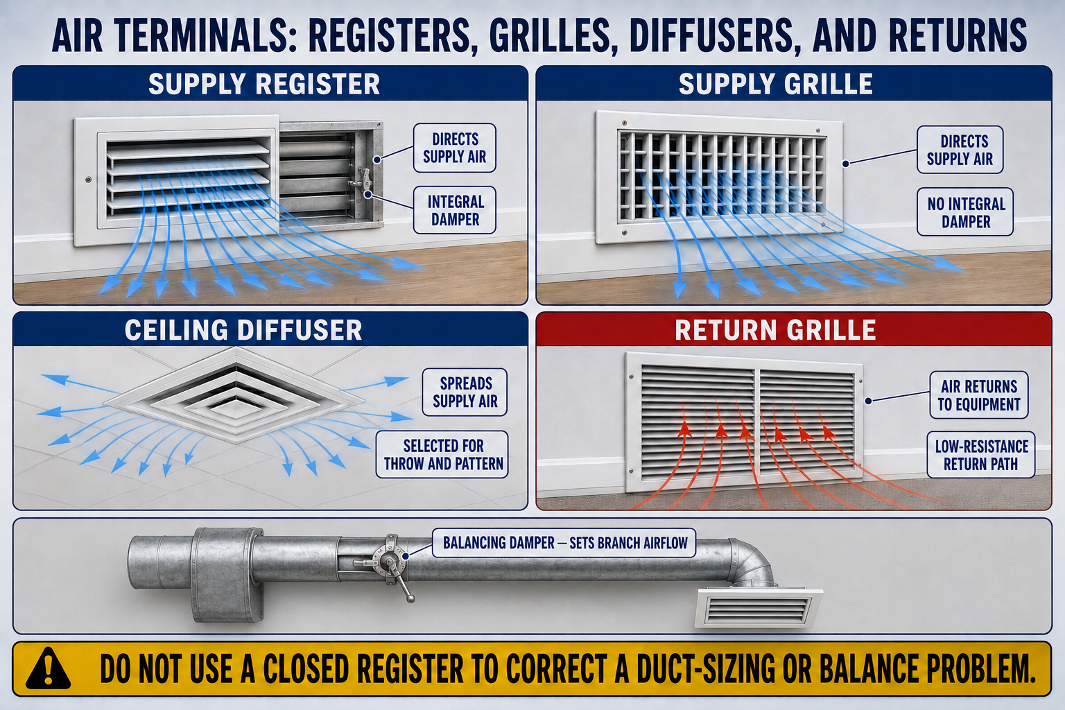
A register is generally a grille combined with an integral damper or other airflow-control device. Adjustable face blades may direct the discharge, but the face control is not a substitute for a properly located branch balancing damper.
Grille
A grille is a covering with openings or blades through which air passes. It may be used for supply, return, transfer, or exhaust service and may have fixed or adjustable blades without an integral volume-control damper.
Diffuser
A diffuser is designed to distribute supply air in one or more controlled directions while encouraging room-air mixing. Ceiling diffusers commonly produce radial, directional, or linear patterns.
Return Inlet
A return grille admits room air into the return system. It should provide adequate free area with acceptable pressure drop and sound while resisting blockage by furniture, doors, rugs, filters, or stored material.
Two terminals with the same listed face dimensions can have different free area, pressure drop, airflow pattern, sound, throw, and appearance. Use the manufacturer’s performance data for the exact model and neck size.
Deliver Air Far Enough—Then Slow It Before It Reaches Occupants
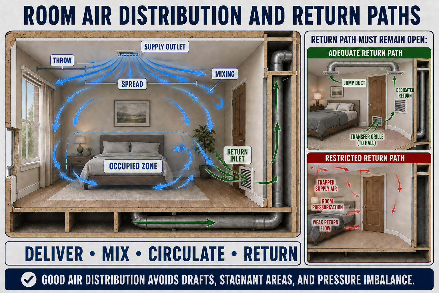
A supply terminal must move conditioned air into the room, mix it with room air, and avoid objectionable drafts or stagnant zones. The visible direction of the blades is only one part of the pattern. Airflow rate, neck velocity, pressure at the terminal, discharge temperature, mounting surface, nearby walls, ceiling geometry, and furniture all influence the result.
Throw
Throw is the distance the supply-air stream travels to a stated terminal velocity. Catalog throw values must be interpreted with the manufacturer’s stated test condition and velocity endpoint.
Spread
Spread describes how the air pattern widens or fans outward. Blade setting, diffuser pattern, ceiling attachment, and airflow rate affect the area served.
Drop
Drop is the vertical distance the air stream falls below the outlet before reaching the stated terminal velocity. Cool supply air and reduced airflow can increase separation from a ceiling under some conditions.
Terminal Velocity
Terminal velocity is the air-stream speed at the endpoint used to report throw. It is not the velocity inside the duct or at the outlet face.
Entrainment
A moving supply jet draws surrounding room air into the stream. This mixing changes the air stream’s volume, temperature, and velocity as it travels.
Occupied Zone
The objective is acceptable temperature and air motion where occupants live and work, not simply a strong air stream that reaches the opposite wall.
A narrow high-velocity jet may feel strong while delivering less air than required, and a properly selected diffuser may move substantial air at a lower face velocity. Use measurements and terminal data.
Match the Outlet to the Room and Operating Mode
Cooling Operation
Cooler supply air is denser than room air. Ceiling or high-sidewall outlets must have enough pattern and attachment to distribute cooling without dumping cold air into the occupied zone.
Heating Operation
Warmer supply air tends to rise. High outlets need sufficient throw and downward pattern where required, while floor or low-wall outlets must avoid short-circuiting and localized drafts.
Perimeter Loads
Windows and exterior surfaces can create heating loss, solar gain, downdrafts, or radiant discomfort. Terminal location and pattern should address the actual load rather than merely the easiest duct route.
Obstructions
Furniture, curtains, rugs, doors, beams, lighting, soffits, shelving, and architectural features can block or redirect supply and return airflow.
Pressure and Sound
The terminal requires enough inlet pressure to produce its rated pattern, but excessive velocity or throttling can create objectionable sound. Compare measurements with exact product data.
Heating and Cooling Compromise
A shared system may use one terminal layout for both seasons. Selection, blade setting, airflow, and blower staging must provide acceptable performance across intended modes.
ACCA Manual T addresses the selection, sizing, and location of supply outlets and return inlets for residential and small commercial applications. A calculated branch CFM does not by itself select the terminal.
Provide a Quiet, Unobstructed Path Back to the Blower
Return inlets do not need to throw air across a room, but their free area, face velocity, filter arrangement when applicable, location, and duct connection affect noise and resistance. Return air must enter without excessive velocity and then travel through a return system sized for the combined airflow.
Free Area
Face dimensions include blades and frame material that block part of the opening. Use published free area and pressure-drop data rather than assuming the entire nominal rectangle carries air.
Face Velocity
Excessive velocity can create grille noise, drafts, high pressure drop, and rapid filter loading. A larger grille or greater filter area may reduce these effects.
Location
Place returns where they can remain open to room air and support circulation. Avoid locations likely to be covered by furniture, doors, storage, rugs, or occupant modifications.
Filter Grilles
A return filter grille adds the resistance of the filter and may require substantial face area for acceptable pressure drop. Evaluate it as part of the complete filter and return system.
Central Returns
One or more central return grilles can work only when air from supplied spaces has an adequate route back to them under normal door positions.
Dedicated Returns
A dedicated return can provide a direct path from a room, but it must be correctly sized, sealed, balanced, and located in accordance with the design and applicable requirements.
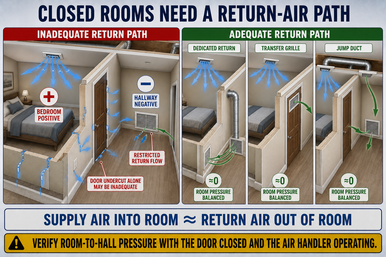
When a door closes and the return path is inadequate, room pressure rises until leakage and reduced supply flow establish a new balance. The result can be lower room airflow, greater building leakage, comfort problems, and pressure changes elsewhere.
Test the Return Path Under Real Door Conditions
Establish the test condition.
Operate the system at the specified or highest design fan airflow, install a clean representative filter, open intended supply and return paths, and place interior doors in the condition being evaluated.
Set the reference.
Use a low-pressure differential manometer with one pressure reference in the closed room and the other in the main body of the house, commonly by passing tubing beneath the door.
Record sign and magnitude.
A room receiving supply air without enough return path normally becomes positive relative to the hall. Record the tubing arrangement so the pressure sign is interpreted correctly.
Compare door positions.
Measure with the door open and closed when diagnosing an occupancy complaint. A major change connects the problem to the room’s return pathway or pressure relationship.
Correct the pathway.
Use the approved design solution, which may include a properly sized dedicated return, transfer grille, jump duct, or another code-compliant return path.
Retest after repair.
Repeat the room-pressure and delivered-airflow measurements with the same fan setting and door positions, then verify that sound, privacy, and fire or smoke requirements remain satisfied.
For applicable ENERGY STAR Single-Family New Homes verification, the referenced federal guidance states that closed rooms should measure from −3 Pa through +3 Pa relative to the main body of the house, with a range of −5 Pa through +5 Pa allowed for rooms designed for at least 150 CFM. Treat these as program criteria, not as a universal code limit for every existing building.
Carpet, flooring changes, door replacement, and small clearances can reduce the opening. Verify the installed return path by measurement instead of assuming that visible clearance below the door is enough.
Choose a Path That Moves Air Without Creating New Problems
Dedicated Return Duct
A duct from the room to the return system provides a direct route but adds duct and fitting resistance and must be sealed, supported, insulated where required, and balanced.
Transfer Grille
A transfer grille connects the closed room with a hall or common area leading to a central return. Its free area, path resistance, sound transfer, light transfer, privacy, and fire separation must be considered.
Jump Duct
A jump duct connects grilles in the closed room and an adjacent common area. Boots, duct size, fittings, flex installation, sealing, insulation, and grille free area all affect performance.
Door Undercut
An undercut may contribute to the path, but its actual free opening can be small and easily obstructed. Do not rely on it without demonstrating acceptable pressure balance.
Return-air openings and transfer paths must comply with applicable mechanical, fuel-gas, fire, smoke, and building requirements. Avoid drawing contaminants, moisture, or odors from prohibited locations, and verify local requirements before modifying the return system.
Choose the Instrument for the Air Pattern
Airflow measurements at registers and grilles are valuable only when the instrument and procedure suit the terminal. Swirling, angled, low-velocity, or nonuniform flow can challenge a basic hood or vane-anemometer reading. Review the airflow instruments in Lesson 7 before selecting the test method.
Flow Hood
A hood captures the terminal discharge or inlet and reports volume. The hood must cover the terminal, be appropriate for flow direction and range, and introduce acceptably small test pressure or compensate for it.
Powered Flow Hood
A powered or pressure-compensating device can reduce the influence of hood backpressure and is useful when accurate terminal airflow is required under difficult conditions.
Velocity Traverse
A defined velocity grid across a known effective area can estimate airflow when the flow field and instrument are suitable. One center reading is not a traverse.
Duct Traverse
A properly located pitot or thermal-anemometer traverse in a straight duct section may provide a better branch measurement than a turbulent terminal, but it requires adequate access and correct procedure.
An instrument can display the same incorrect value repeatedly when the hood, correction factor, effective area, placement, flow direction, or terminal pattern is unsuitable. Validate the method and understand its limitations.
Adjust Distribution Only After Establishing Total Airflow
Balancing distributes available system airflow among branches and terminals to approach the design values. It cannot create missing blower capacity, correct a plugged coil, eliminate undersized trunk resistance, repair leakage, or compensate for an inadequate return system. Correct system-level defects before fine branch adjustment.
Obtain the design targets.
Use room-by-room supply airflow, return strategy, terminal schedules, damper locations, blower settings, and commissioning documents when available.
Prepare the system.
Verify filter and coil condition, equipment assembly, duct integrity, terminal condition, zone operation, intended register positions, and access to balancing dampers.
Confirm the operating point.
Measure TESP at the correct boundaries, identify the actual blower setting, and use applicable manufacturer data or another validated method to establish total airflow.
Measure every terminal.
Record supply and return readings using a consistent validated method and calculate each measured supply outlet as a percentage of its design target.
Adjust branch dampers.
Begin with measured evidence, use the intended balancing devices, make small changes, and avoid fully closing a path unless the design specifically requires that condition.
Remeasure interacting branches.
Throttling one path changes system resistance and redistributes airflow through parallel paths. Repeat the terminal survey after each meaningful group of adjustments.
Verify room pressure and comfort.
Test closed-room pressure, terminal pattern, noise, room temperature response, and the original complaint under representative operating conditions.
Complete final system checks.
Recheck TESP, blower airflow, equipment temperatures, safety limits, motor operation, and total delivered airflow, then mark and document final damper positions.
Use Each Device for Its Intended Purpose
Branch Balancing Damper
A damper near the branch takeoff controls the branch before the air reaches the room. It can reduce outlet noise and preserve the terminal pattern compared with severe face throttling.
Register Damper
An integral register damper permits occupant control and limited adjustment, but closing it substantially can increase noise, distort the pattern, and redirect airflow elsewhere.
Directional Blades
Face blades aim the supply pattern. Extreme blade angles can reduce throw, raise noise, and change measured airflow, so adjust them according to terminal purpose rather than appearance alone.
Return Grille
Do not throttle a return grille as a routine balancing method. Added return restriction can raise system static pressure, reduce airflow, and create noise without correcting supply distribution.
Room terminals are part of the designed air-distribution pattern. Use accessible branch dampers, measure every affected path, and verify the total system instead of balancing by sound or hand feel.
Trace the Symptom Beyond the Terminal
Room Changes with Door Position
Measure room-to-hall pressure and supply airflow with the door open and closed. Inspect dedicated returns, transfer grilles, jump ducts, and undercuts.
Strong Draft but Poor Comfort
Evaluate outlet selection, pattern, discharge temperature, occupied-zone velocity, room load, cycling, and mixing rather than assuming more airflow is needed.
Whistling or Rushing Sound
Check blocked or undersized free area, high velocity, closed dampers, restrictive boots, filter loading, excessive system static, and abrupt fittings.
Weak Remote Outlet
Inspect its branch takeoff, damper, leakage, flex installation, fittings, boot, and terminal before reducing airflow to every nearby room.
Uneven Seasonal Comfort
Compare heating and cooling airflow settings, load differences, supply temperature, outlet pattern, equipment runtime, solar exposure, and return paths.
Dust at a Grille
Determine whether deposits come from filtration, duct leakage, room-air entrainment, surface condensation, or local airflow patterns rather than assuming the duct contains heavy contamination.
Can You Evaluate Terminals, Returns, and Balance?
- What commonly distinguishes a register from a grille?
- How does a diffuser differ from a simple supply grille?
- What do throw, spread, drop, and terminal velocity describe?
- Why can two terminals with the same face dimensions perform differently?
- How can cooling and heating operation require different supply-air patterns?
- Why is grille free area more useful than nominal face area when evaluating resistance?
- What happens when supply air enters a closed room without an adequate return path?
- How is closed-room pressure measured relative to the main body of the house?
- What return-path options can serve a room that is frequently closed?
- Why should a door undercut not be assumed adequate without testing?
- Why can a flow hood affect the airflow it is trying to measure?
- What system conditions must be corrected before fine balancing?
- Why must other terminals be remeasured after a branch-damper adjustment?
- Why is closing supply registers not a complete balancing procedure?
What You Should Have Learned
Registers, grilles, diffusers, and return inlets have different construction and performance even when their visible face dimensions appear similar.
Supply-terminal selection must consider airflow, pressure drop, throw, spread, drop, terminal velocity, sound, mounting location, discharge temperature, and occupied-zone comfort.
Manufacturer performance data for the exact terminal is more reliable than judging airflow by face size, blade appearance, hand feel, or a generic grille value.
Return grilles need adequate free area and a quiet, unobstructed connection to a return system capable of carrying the combined airflow.
Every normally closed supplied room needs an adequate return path through a dedicated return, transfer grille, jump duct, or another approved arrangement.
A low-pressure manometer can reveal whether closing a door creates a meaningful room-to-house pressure imbalance that affects airflow and comfort.
Balancing begins with correct total system operation and uses measured airflow plus intended branch dampers, followed by repeated measurements of interacting paths.
Final verification includes TESP, blower airflow, temperatures, room delivery, pressure balance, terminal pattern, sound, damper position, and the original comfort complaint.