Fittings, Flexible Duct, and Effective Length
A duct path that measures only a few dozen feet can behave like hundreds of feet of straight duct after elbows, takeoffs, transitions, boots, dampers, junctions, and other fittings are included. Flexible duct can add still more resistance when it is left compressed, routed through tight bends, allowed to sag, crushed by supports, or installed with unnecessary length.
This technician-focused lesson explains how fitting geometry and flexible-duct installation affect pressure loss and airflow. It builds on the Manual D relationships introduced in Lesson 12 and shows how effective length can guide field inspection, diagnosis, and repair without pretending that one generic fitting value applies to every system.
What You Will Learn
By the end of this lesson you should be able to:
Distinguish physical length from effective length.
Explain why the resistance of fittings must be added to the measured length of straight duct.
Interpret fitting equivalent length.
Describe equivalent length as a way to represent fitting resistance rather than as the fitting’s physical dimension.
Recognize high-resistance fitting conditions.
Evaluate elbows, takeoffs, transitions, tees, wyes, boots, dampers, and closely spaced fittings by their actual geometry and airflow path.
Inspect flexible duct correctly.
Identify compression, sag, excess length, kinks, sharp bends, crushed insulation, poor supports, and faulty collar connections.
Connect restrictions with pressure and airflow.
Use static-pressure, component pressure-drop, blower, and delivered-airflow measurements to test whether an observed condition is affecting performance.
Repair and verify.
Select practical corrections for fittings and flexible duct, then repeat the original measurements to confirm the result.
Air Must Turn, Divide, Join, Expand, and Contract
Straight duct creates friction along its walls, but a real air-distribution system is not one straight tube. Air changes direction at elbows, divides at supply takeoffs, joins at return fittings, changes area through transitions, passes dampers and terminal devices, and enters or exits equipment and plenums. Every disturbance changes velocity and pressure and can create separation, turbulence, or uneven flow.
Direction Changes
Elbows and offsets make air turn. Smooth radius, appropriate throat geometry, and properly applied turning vanes can reduce loss compared with an abrupt or poorly constructed turn.
Flow Divisions
Takeoffs, tees, wyes, and junction boxes divide supply air among parallel paths. Entry angle, branch geometry, area, velocity, and airflow split affect the resistance of each path.
Flow Combinations
Return branches joining a trunk can create interaction and turbulence. A fitting that performs acceptably in one flow direction may not have the same loss when the direction or airflow division changes.
Area Changes
Transitions connect different duct sizes or shapes. Abrupt contractions and expansions generally disturb flow more than correctly proportioned gradual transitions.
A fitting should be evaluated by the route the air actually takes through it, not by its name alone. Two fittings both called elbows or takeoffs can have very different pressure losses.
Represent a Fitting’s Resistance as Straight Duct
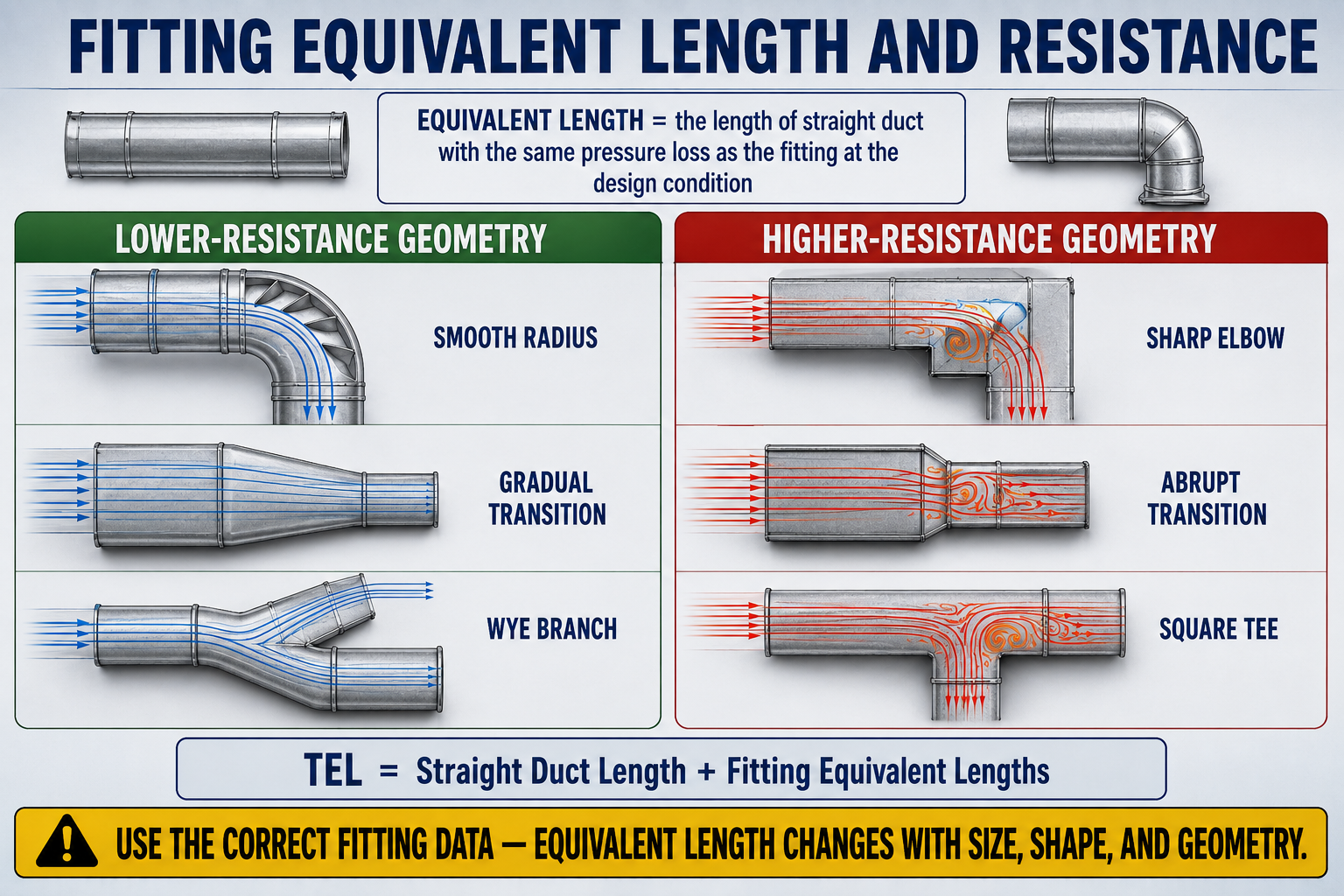
Equivalent length is the length of straight duct that would produce a comparable pressure loss to a particular fitting under the specified conditions. It converts fitting resistance into a form that can be combined with straight duct length during the Manual D procedure.
Measured Developed Length
Follow the actual duct route along its centerline rather than measuring a straight line between the equipment and terminal.
Straight Length + Fitting Equivalent Lengths
Add the applicable equivalent length of each fitting included in the selected supply-and-return circulation path.
Assume a complete supply-and-return path contains 70 feet of measured straight duct and the correctly selected fitting data adds 150 feet of equivalent length. The path has a total effective length of 220 feet. The example shows why fittings can dominate resistance; it does not assign a standard value to any particular elbow, takeoff, or transition.
A compact fitting can have a large equivalent length because the value represents pressure loss, not physical size. Use the exact fitting description, geometry, airflow path, and applicable Manual D data or approved software.
The Details Determine the Resistance
Equivalent-length data is specific. A technician reviewing a design or installation must identify more than the nominal duct size. Shape, radius, throat, turning vanes, transition angle, area ratio, takeoff construction, branch position, airflow division, and flow direction can all affect the correct selection.
Elbow Geometry
A smooth-radius elbow, a square-throat elbow, a mitered elbow, and an elbow with turning vanes are not interchangeable entries. Construction and vane condition must match the data used.
Branch Entry
A straight tap, conical takeoff, scoop, tee, and wye guide air into a branch differently. Branch airflow and the relationship between branch and trunk sizes matter.
Transitions
Length, angle, offset, inlet and outlet area, and whether the fitting expands or contracts affect loss. A visually small transition can still produce severe disturbance.
Entries and Exits
Air entering from a plenum or leaving into a boot, box, grille, register, or diffuser encounters conditions that are part of the path and must not be ignored.
Dampers and Accessories
Balancing dampers, backdraft dampers, fire or smoke dampers, coils, filters, and accessories create resistance that must be handled within the correct design or equipment boundary.
Installed Condition
Damaged vanes, internal screws, loose liner, sealant intruding into the airway, offset connections, and field-fabricated geometry can make actual performance differ from the selected fitting.
Small Layout Decisions Can Consume the Pressure Budget
Sharp Turns at Equipment
An abrupt return or supply elbow attached directly to a blower, coil, or plenum can create uneven inlet or outlet conditions in addition to the elbow’s own resistance.
Poor Branch Takeoffs
A branch that receives little air may have an abrupt or poorly oriented takeoff, excessive downstream resistance, or inadequate pressure—not simply a duct that is too small.
Opposed Fittings
Closely spaced turns, transitions, dampers, and takeoffs may interact before airflow has stabilized. Isolated fitting data may not represent a crowded field assembly perfectly.
Abrupt Size Reductions
Reducing area does not force a guaranteed airflow downstream. It increases velocity and resistance and can produce noise while moving less air at the system operating point.
Restricted Boots and Boxes
Shallow boots, blocked entries, internal insulation, construction debris, collapsed liners, and mismatched terminal necks can restrict the final portion of a branch.
Hidden Return Restrictions
Stud cavities, panned framing, platform returns, filter grilles, transfer paths, and return drops can contain abrupt turns or narrow openings that are easy to overlook.
A shorter route with several high-loss fittings can have a greater effective length than a longer, straighter route. Manual D uses the applicable total effective length, not visual distance alone.
Know Which Layer Performs Which Job
Typical insulated flexible HVAC duct contains a wire-reinforced inner liner, insulation surrounding that liner, and an outer jacket that protects the insulation and serves as the vapor-retarder layer when the product is designed for that purpose. Correct installation must preserve the function of all layers.
Inner Liner
The inner liner forms the air passage. It must be pulled sufficiently taut, kept open through bends, fully connected to collars, mechanically secured, and sealed using approved materials and instructions.
Wire Helix
The helix gives the duct its round shape and flexibility. Crushing, kinking, or sharply bending the helix reduces the airway and raises resistance.
Insulation
The insulation limits heat transfer between the airstream and surrounding space. Compressed, missing, wet, or poorly restored insulation can create thermal loss and condensation risk.
Outer Jacket
The outer jacket encloses the insulation and protects the assembly. It is not a substitute for connecting and sealing the inner air liner to the collar.
A branch can appear connected while the inner liner is loose, folded, torn, or separated beneath the insulation. Inspect or test the actual air seal when evidence points to leakage or restriction.
Installation Determines Performance
Compression
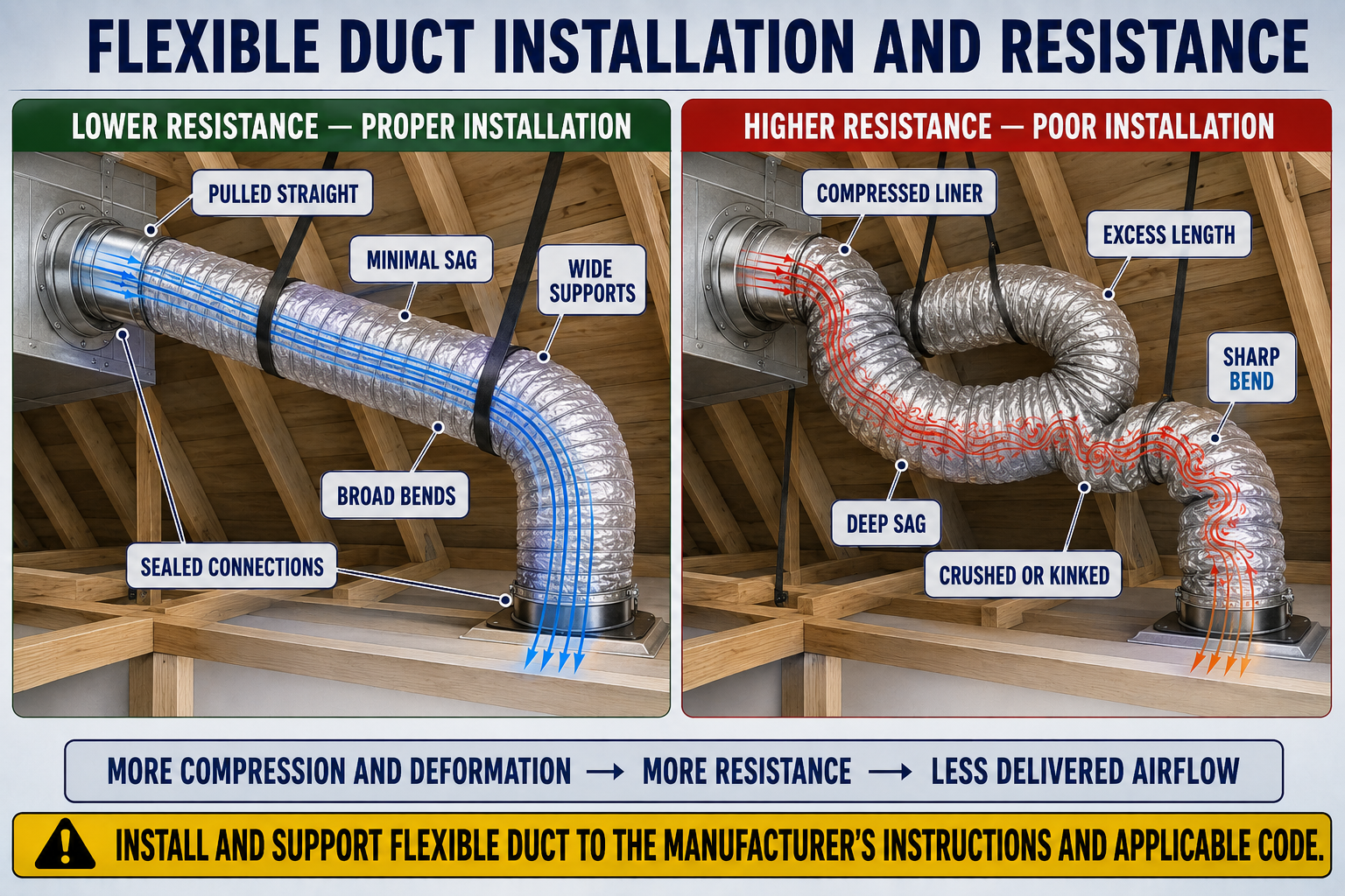
Leaving the inner liner bunched together increases surface irregularity and turbulence. Even when the duct is not crushed from the outside, unused length compressed into the run can greatly increase resistance.
Sag
Excess sag lengthens and deforms the airflow path. Supports must be placed and shaped so the duct remains open without concentrating force at narrow straps.
Sharp Bends
A tight bend can collapse the inner radius and create a severe local restriction. Provide a gradual bend and suitable support, especially near collars and boots.
Excess Length
Loops and unnecessary routing add straight resistance, bends, compression, and sag. Use the shortest practical route that preserves proper bend geometry and service access.
Crushed Sections
Framing, stored materials, piping, wiring, access traffic, or overtight supports can reduce area. A partially flattened duct can become the dominant restriction in a branch.
Poor Collar Alignment
A duct pulled sideways immediately after a collar can kink at the connection. Allow a straight supported approach before changing direction where the installation permits.
Support spacing, strap or saddle width, allowable sag, bend geometry, connection methods, sealing materials, and fire or smoke requirements vary with the listed product and jurisdiction. Follow the duct manufacturer’s installation instructions and the applicable adopted code rather than relying on one number for every installation.
Install the Air Path Before Finishing the Jacket
Prepare the route.
Choose a direct path with enough clearance for the duct diameter, insulation, gradual bends, supports, future access, and protection from other trades.
Cut excess length.
Fit the duct to the route instead of storing unused material in loops, compressed sections, or deep sags.
Connect the inner liner.
Extend the liner over the approved collar engagement area, mechanically fasten it, and seal it with materials and methods required by the product instructions and applicable code.
Restore insulation and jacket.
Bring the insulation into place without gaps or heavy compression and close the outer jacket so its protective and vapor-control functions are maintained.
Support without constricting.
Use supports that maintain the duct’s shape, limit sag, and protect insulation. Add support around bends and connections as required.
Inspect the completed run.
Look from several angles for flattened areas, hidden kinks, compression, sharp turns, unsupported weight, damaged jacket, and contact with hazards.
A support can prevent sag yet still create a restriction if it squeezes the inner core or insulation. The finished run should remain open and round through the supported area.
Use Inspection to Direct Measurements
A visible defect is useful evidence, but diagnosis should connect that condition with the system complaint and measured performance. One kinked branch can reduce airflow to a room while leaving total external static pressure only modestly changed; a restricted main return can affect the entire system. The measurement plan must match the suspected scope.
Define the complaint.
Determine whether the problem affects one outlet, one room, a group of branches, one zone, one operating mode, or the complete system.
Trace the complete path.
Follow the supply route from equipment to terminal and the return route back to the equipment, identifying fittings, dampers, flex condition, restrictions, leakage, and return-path limitations.
Verify system airflow conditions.
Measure TESP at correct locations, identify the blower setting, consult manufacturer performance data, and confirm that filter, coil, and equipment restrictions have been evaluated.
Bracket the suspect section.
When suitable test locations and instrument accuracy permit, compare static pressure before and after a suspect assembly to determine whether it consumes an unusual portion of the pressure budget.
Measure delivered airflow.
Use an appropriate hood, traverse, or other validated method and compare the affected outlet with design values, balancing documentation, similar branches, and the room complaint.
Correct and retest.
Repair the proven condition, return panels, filters, dampers, doors, and blower settings to their final positions, and repeat the original pressure and airflow measurements.
TESP describes the operating resistance across the defined equipment test boundary. A local branch restriction may need branch airflow, duct static pressure, room pressure, temperature, and physical inspection to reveal its effect.
Reduce the Proven Restriction and Preserve Distribution
Improve the Fitting
Replace an abrupt or damaged fitting with correctly sized geometry, radius, vanes, transition, takeoff, or junction arrangement supported by the design and available space.
Correct Flexible Duct
Shorten excess material, extend the inner liner, remove loops and kinks, improve bends, repair crushed areas, and add non-constricting supports according to approved instructions.
Repair Connections
Reconnect and seal the inner air liner, mechanically secure it, restore insulation, and close the jacket while confirming that sealant or liner does not obstruct the airway.
Reconsider the Route
A rerouted branch may remove several turns or allow a larger bend radius, but the change must preserve fire, structural, electrical, plumbing, access, insulation, and code requirements.
Protect Other Branches
Reducing one path’s resistance changes airflow distribution among parallel paths. Verify damper positions and rebalance rather than assuming every room benefits equally.
Document the Result
Record the original defect, pressure and airflow readings, repair, final blower setting, damper positions, and post-repair measurements.
Increasing blower speed may raise airflow in some systems, but it can also increase static pressure, noise, leakage, fan power, and airflow imbalance. Correct the proven restriction and verify the complete system before changing the designed operating setting.
Match the Evidence to the Likely Scope
One Weak Outlet
Inspect its register, boot, damper, branch takeoff, flex run, collar connections, leakage, and room return path before changing the blower.
Several Weak Outlets
Look for a common restricted trunk, zone damper, transition, junction, return path, or upstream flex section serving the affected group.
High Static and Low Airflow
Profile pressure drops across the filter, coil, equipment, return, and supply sections, then inspect the portion consuming excessive pressure.
High Static with Constant-Airflow Blower
The motor may increase speed and power to maintain airflow within its limits. Noise or energy use can reveal a restriction before delivered airflow falls severely.
Noise at a Fitting
Check velocity, abrupt geometry, loose material, damper position, vane condition, leakage, and the interaction of nearby fittings rather than treating sound alone as proof of airflow.
Condensation at a Support
Inspect for compressed or missing insulation, a damaged jacket or vapor retarder, air leakage, surrounding dew-point conditions, and improper contact with cold surfaces.
Can You Evaluate Fittings and Flexible Duct?
- What is the difference between measured straight length and effective length?
- What does fitting equivalent length represent?
- Why can a physically short duct path have a large total effective length?
- Why should every elbow not be assigned the same equivalent length?
- Which fitting details can change the correct equivalent-length selection?
- Why can a shorter duct route become the critical design path?
- How do compression and sag increase the resistance of flexible duct?
- Why should excess flexible duct be cut to fit rather than stored in the run?
- What can happen when a flexible duct makes a sharp bend immediately at a collar?
- Why must supports hold the duct without constricting it?
- What is the difference between the function of the inner liner and the outer jacket?
- Why may TESP alone fail to identify a restricted individual branch?
- What measurements can verify whether a fitting or flex repair improved performance?
- Why can increasing blower speed be an inappropriate response to a duct restriction?
What You Should Have Learned
Total effective length combines measured straight duct length with the applicable equivalent lengths of fittings along the supply-and-return design path.
Equivalent length represents resistance, not physical size, and must be selected for the actual fitting geometry, airflow path, and operating condition.
Elbows, takeoffs, transitions, tees, wyes, boots, dampers, entries, exits, and junctions can consume a large portion of the duct-system pressure budget.
The path with the greatest applicable effective length may control the design even when another path is physically longer.
Flexible duct resistance rises when the liner is compressed, sagging, kinked, sharply bent, crushed, poorly supported, or routed with unnecessary length.
The inner liner forms the sealed airflow passage; the insulation and outer jacket perform different thermal, vapor-control, and protective functions.
Flexible duct must be installed according to the listed product instructions and applicable code, including requirements for connections, supports, sag, bends, sealing, insulation, and jacket closure.
Inspection identifies suspects, while pressure, blower, airflow, temperature, and room-performance measurements show whether a repair corrected the complete operating problem.