Introduction to ACCA Manual D
A residential duct system should not be sized by square footage, the diameter of the old duct, a favorite friction rate, or the assumption that every room needs the same airflow. The design must connect room-by-room airflow requirements with the selected equipment, actual blower performance, filter and accessory resistance, duct layout, fitting losses, terminal selection, noise control, and balancing.
ACCA Manual D provides the ANSI-recognized procedure for residential duct-system design. This technician-focused introduction does not replace the complete manual, approved software, or formal design training. It explains the relationships technicians need to recognize design intent, interpret available documentation, evaluate existing systems, and understand why apparently simple duct changes can alter airflow throughout a building.
What You Will Learn
By the end of this lesson you should be able to:
Explain the purpose of Manual D.
Describe how the procedure connects required room airflow, blower performance, component losses, duct resistance, terminals, and balancing.
Recognize the design sequence.
Place Manual D after room-by-room load calculations and equipment selection rather than using duct size to determine equipment airflow.
Determine available static pressure.
Begin with blower performance at design airflow, define the equipment-data boundary, subtract applicable component pressure losses, and identify the pressure available for ducts and fittings.
Explain total effective length.
Combine measured straight length with fitting equivalent lengths so elbows, takeoffs, transitions, and other fittings are represented in the critical design path.
Calculate design friction rate.
Use available static pressure and total effective length instead of assuming that every residential system should be designed at the same friction rate.
Apply Manual D concepts in the field.
Use design documents, physical inspection, pressure, blower data, airflow, temperature, and balancing measurements to evaluate installed performance.
Turn Required Airflow into a Complete Duct Design
Manual D is a duct-system design procedure, not merely a duct-sizing chart. It accounts for the interaction between the blower and the complete supply and return system, including straight ducts, fittings, filters, coils and accessories as applicable, grilles, registers, dampers, return paths, construction methods, noise, leakage, and balancing.
Required Airflow
Each room and zone receives a design airflow derived from its heating and cooling requirements and the selected equipment’s operating conditions.
Blower Capability
The selected blower must produce the required total airflow while operating against the resistance created by the actual equipment and air-distribution system.
Pressure Budget
Filters, coils, heat exchangers, accessories, ducts, fittings, dampers, grilles, and registers consume portions of the pressure produced by the blower.
Distribution
Trunks and branches must carry the assigned airflow to each terminal while return paths allow air to travel back to the equipment without unacceptable pressure imbalance.
Noise and Velocity
Duct and terminal velocities must support acceptable noise and air-distribution performance rather than merely fitting within available framing space.
Testing and Balancing
A designed system still requires correct installation, startup, measurement, damper adjustment, and verification under actual operating conditions.
A duct size selected without the design airflow, pressure budget, material, shape, effective length, fitting geometry, and terminal requirements is not a Manual D design.
Loads, Equipment, Air Distribution, and Ducts Must Agree
Manual J: Building Loads
A room-by-room load calculation estimates heating loss and cooling gain under defined design conditions. It establishes how the building and individual rooms contribute to the required capacity.
Manual S: Equipment Selection
Equipment is selected using the load results and manufacturer performance data. Capacity, sensible and latent performance, airflow, heating output, and operating conditions must fit the application.
Manual T: Air Distribution
Supply outlets and return inlets are selected and located to provide suitable throw, spread, mixing, noise, pressure drop, and occupied-zone comfort.
Manual D: Duct System
The supply and return ducts are laid out and sized to move the required airflow between the selected equipment and the air terminals.
The correct sequence begins with building loads and equipment performance. Starting with an existing duct size or an assumed airflow can force every later decision to fit an unsupported starting point.
Follow the Design from Room Airflow to Final Balance
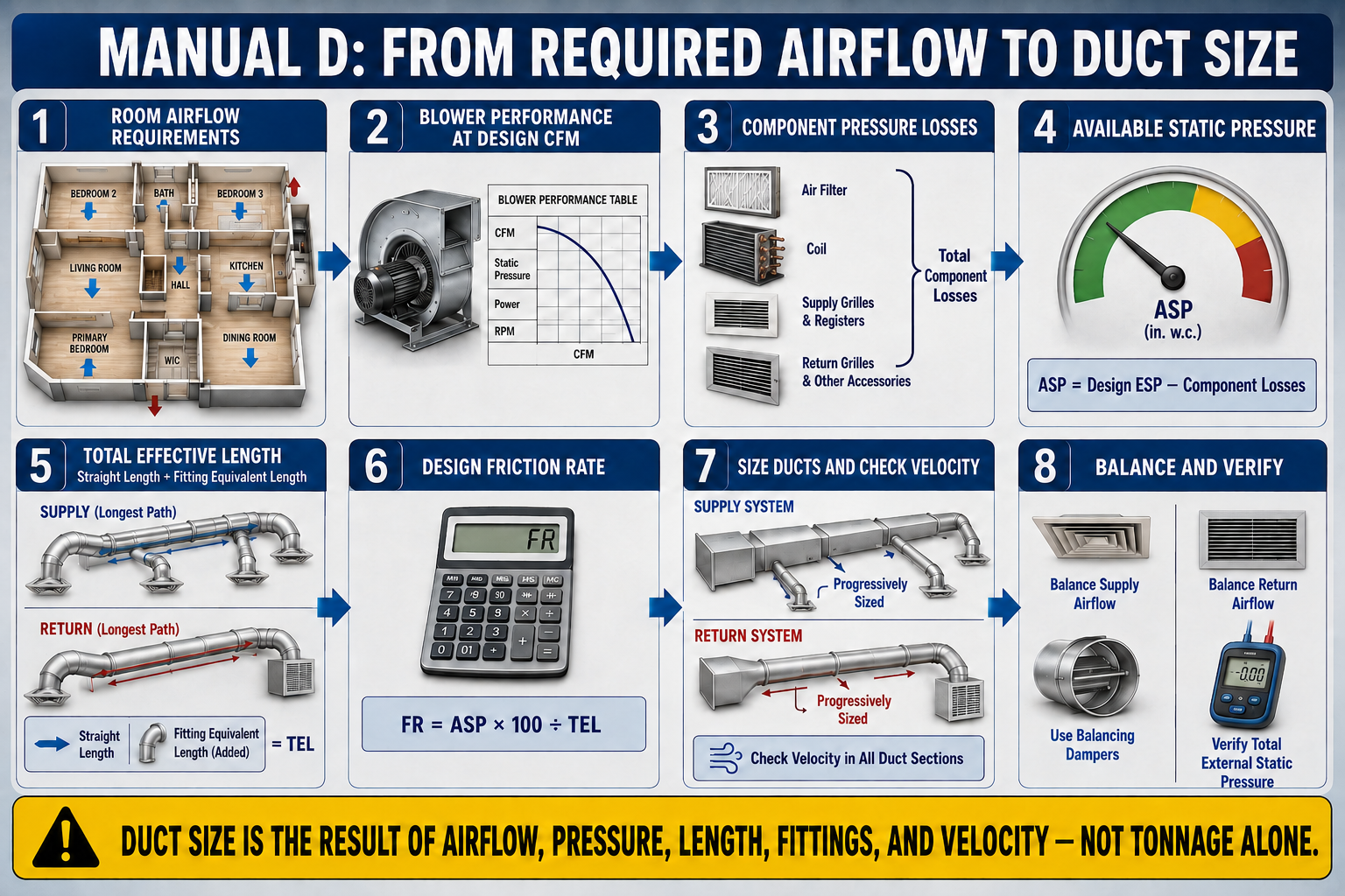
Establish room and system airflow.
Use the room-by-room loads, selected equipment performance, and design temperature relationships to determine required branch and total system airflow.
Select the blower operating point.
Use manufacturer blower data to identify an operating range that delivers design airflow without relying on the extreme end of the fan’s capability.
Lay out supply and return paths.
Locate equipment, trunks, branches, fittings, terminals, and return paths while considering framing, access, insulation, service, leakage, and installation feasibility.
Calculate the pressure budget.
Determine design external static pressure from blower data, subtract applicable component pressure losses, and calculate the static pressure available for ducts and fittings.
Determine total effective length.
Add straight duct length and fitting equivalent lengths along the applicable supply and return design path.
Calculate friction rate.
Divide available static pressure across the total effective length using the Manual D relationship expressed per 100 feet.
Size ducts and verify velocity.
Use approved procedures or software to size each section for its assigned airflow, then evaluate velocity, noise, fitting conditions, and terminal requirements.
Install, test, and balance.
Build the system to the design, verify leakage and blower operation, measure delivered airflow, adjust balancing dampers, and document final performance.
ACCA-approved software can apply the Manual D procedure, but it cannot compensate for incorrect loads, wrong equipment data, unrealistic fitting selections, inaccurate lengths, omitted components, or a duct layout that cannot be installed as modeled.
Every Duct Section Carries an Assigned Air Quantity
A branch duct carries the airflow assigned to its room or terminal. A trunk section carries the sum of the downstream branches it serves. As branches leave a supply trunk, the airflow assigned to the remaining trunk normally decreases; as return branches join a return trunk, the airflow normally increases toward the blower.
Room Airflow Is Load Based
Rooms of the same floor area can require different airflow because exposure, windows, insulation, infiltration, occupancy, internal gains, and design temperatures differ.
Heating and Cooling May Differ
A room’s heating airflow requirement and cooling airflow requirement may not be the same. The design must address the controlling condition and the equipment’s operating strategy.
Trunk Airflow Changes
A supply trunk does not carry full blower airflow at every point. Each section is sized for the airflow that remains after upstream branch takeoffs.
Return Air Must Complete the Circuit
Supply air delivered to closed rooms needs an adequately sized return path through dedicated returns, transfer grilles, jump ducts, or another approved arrangement.
Dividing total blower airflow equally by the number of supply registers ignores room loads, branch resistance, terminal performance, return paths, and balancing requirements.
Define What the Manufacturer’s External Static Includes
Manual D begins the pressure budget with blower performance at the required design airflow. The technician or designer must use the correct equipment model, motor type, speed or airflow setting, voltage and configuration, and the correct definition of the manufacturer’s external-static-pressure boundary.
Furnace Blower Data
Published furnace tables may represent airflow against external resistance outside the furnace cabinet. An added evaporator coil, filter, air cleaner, or accessory may therefore consume part of the available pressure.
Air-Handler Data
Some air-handler data includes the factory coil within the tested unit while filters, heat kits, accessories, or field configurations require separate corrections or pressure allowances. Use the exact manufacturer’s documentation.
Blower Type Matters
PSC, constant-torque, and constant-airflow blowers respond differently as resistance changes. The design operating point must come from applicable data rather than the motor label alone.
Field TESP Is a Check
Measured TESP reveals the installed operating resistance across defined test points. Use Lesson 9 to review TESP and blower-table interpretation.
If a coil, heat exchanger, filter, or accessory is already included within the manufacturer’s blower-performance boundary, subtracting its pressure loss again produces an incorrect available-static calculation. Define every boundary before building the pressure budget.
What Remains for the Ducts and Fittings
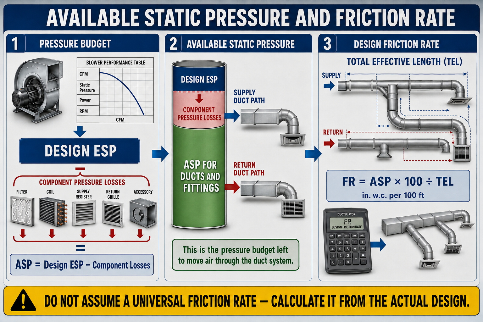
ASP = Design ESP − Component Pressure Losses
Subtract only the losses assigned outside the duct-and-fitting calculation and not already included within the blower-data boundary.
FR = (ASP × 100) ÷ TEL
Friction rate is expressed as pressure loss per 100 feet of effective length and is calculated for the design, not selected as a universal constant.
Design ESP
Select the external static pressure at which the blower produces the required design airflow using the applicable manufacturer performance table or curve.
Component Losses
Account for filters, coils, heat exchangers, air cleaners, grilles, registers, dampers, and accessories according to the defined equipment boundary and Manual D procedure.
Remaining Pressure
The pressure left after component allowances is what the design can spend moving air through supply and return ducts and their fittings.
Small ASP
If little pressure remains, forcing the calculation through small ducts produces excessive friction, noise, or inadequate airflow. Reconsider components, filter area, layout, fittings, blower selection, or equipment configuration.
If the selected blower produces design airflow at 0.50 in. w.c. external static and applicable component losses outside the duct-and-fitting calculation total 0.28 in. w.c., the available static pressure is 0.22 in. w.c. If the design path has a total effective length of 220 feet, the friction rate is (0.22 × 100) ÷ 220 = 0.10 in. w.c. per 100 feet.
The example produces 0.10 only because of its specific available static pressure and total effective length. A real system may calculate differently, and the design must use its own airflow, blower data, component losses, layout, and fittings.
Fittings Make the Air Path Longer Than a Tape Measure Shows
Total effective length combines measured straight duct length with the equivalent lengths assigned to fittings along the design circulation path. Equivalent length expresses a fitting’s resistance as the length of straight duct that would create a comparable pressure loss under the procedure; it is not the fitting’s physical dimension.
Straight Length
Measure the developed centerline length of supply and return duct sections included in the path rather than using only straight-line distance between equipment and room.
Equivalent Length
Add the applicable values for takeoffs, elbows, transitions, boots, entries, exits, wyes, tees, junction boxes, and other fittings using the correct geometry and table.
Critical Path
The path controlling friction-rate calculation is identified by total effective length, not by whichever branch appears physically farthest from the equipment.
Supply Plus Return
The design circulation path includes the applicable supply and return effective lengths used by the Manual D procedure because the blower must move air through the complete circuit.
Equivalent length changes with fitting type, radius, throat, vanes, area ratio, branch geometry, airflow division, and installation. Lesson 13 examines fittings and flexible-duct effects in greater detail.
Use Airflow and Calculated Friction Rate Together
Once design airflow and friction rate are known, each duct section can be sized using the applicable Manual D method, friction chart, duct calculator, worksheet, or ACCA-approved software. The result must then be checked against velocity, noise, construction, and terminal requirements.
Branch Duct
Size each branch for the airflow assigned to the room or terminal while accounting for material, shape, length, fittings, installation, and balancing.
Trunk Section
Size each trunk section for the sum of the downstream airflow it carries. Reducing trunks and extended plenums must reflect where branch airflow leaves or joins the trunk.
Velocity Check
A duct can satisfy a friction calculation yet create unacceptable velocity or noise. Check duct airways, grilles, registers, and return paths using applicable Manual D and terminal data.
Terminal Pressure
Registers, grilles, and diffusers need suitable inlet conditions and pressure to produce their rated throw, spread, airflow, and sound performance.
Reducing duct size increases resistance and velocity. Airflow follows the operating point created by the blower and all parallel system paths; an undersized branch can receive less air, create more noise, and disturb airflow elsewhere.
Calculated Airflow Still Requires Field Adjustment
Branches with different lengths and fitting losses do not automatically deliver design airflow simply because their nominal duct sizes were calculated. Manual D includes balancing because installed resistance, fitting performance, construction tolerances, leakage, terminal conditions, and actual blower operation differ among paths.
Use Branch Dampers
Locate balancing dampers where they can adjust branch airflow without using the room register as the primary throttling device and without making future service impractical.
Measure Delivered Air
Use an appropriate airflow hood, traverse, or other validated method while accounting for terminal type, flow pattern, instrument limitations, and system configuration.
Verify Return Paths
Check room-to-hall pressure with doors in their normal closed position and confirm that central returns, dedicated returns, transfer grilles, or jump ducts provide an adequate path.
Recheck the Whole System
Damper adjustments change system resistance and parallel flow distribution. Repeat TESP, blower airflow, temperatures, noise, and critical-room measurements after balancing.
Partially closing terminal blades can increase noise, distort throw, raise local resistance, and change total system operation. Use designed balancing devices and verify the result with measurements.
Compare Design Intent with Installed Performance
A service technician may not receive complete design documents, but Manual D relationships still organize the diagnosis. The goal is not to reverse-engineer an entire design from one static-pressure reading; it is to combine documentation, inspection, equipment data, pressure, airflow, temperature, leakage, and room-delivery evidence.
Collect available documentation.
Look for room loads, design airflow, equipment selection, blower settings, duct plans, sizes, fitting schedules, balancing reports, startup readings, and later modifications.
Trace the installed system.
Compare the actual layout with available plans and identify added fittings, long flex runs, missing returns, altered trunks, closed dampers, disconnected ducts, and inaccessible balance devices.
Verify equipment airflow.
Measure TESP at the correct boundaries, identify the actual blower setting, use manufacturer data, and compare cooling and heating temperatures with applicable equipment information.
Profile component resistance.
Use Lesson 10 to locate excessive losses across filters, coils, equipment sections, ducts, fittings, dampers, and terminals.
Measure room delivery.
Compare register airflow, room temperature, return-path pressure, noise, throw, and the customer’s complaint with the expected use of each room.
Correct and verify.
Repair the proven defect, restore the final configuration, repeat the original measurements, and document whether the complete system now operates correctly.
Avoid These Design and Field Errors
Using 0.10 as a Default
Friction rate must be calculated from the available static pressure and total effective length for the actual design.
Using Physical Length Only
Ignoring fitting equivalent lengths can severely understate resistance, especially in compact layouts with many elbows, transitions, takeoffs, and junctions.
Ignoring the Return System
The blower moves air through a complete circulation path. Undersized returns and closed-room pressure imbalances can undermine an otherwise adequate supply layout.
Using Nominal Equipment Airflow
Nameplate size or a rule of thumb does not replace manufacturer blower performance at the actual setting and external resistance.
Sizing Every Section for Full Airflow
Trunk airflow changes as branches leave or join. Each section must be sized for the airflow assigned to that part of the system.
Treating Design as Commissioning
A calculated design does not prove that the installed system matches it. Leakage testing, startup, pressure measurements, airflow balancing, and final verification remain necessary.
Can You Interpret the Manual D Design Process?
- Why is Manual D more than a chart that matches CFM with duct diameter?
- What information should be established before beginning a residential duct design?
- How do Manuals J, S, T, and D relate to one another?
- Why must the blower-performance boundary be defined before calculating available static pressure?
- How is available static pressure calculated?
- What is included in total effective length?
- Why can the critical design path differ from the physically longest duct run?
- How is design friction rate calculated?
- Why should 0.10 in. w.c. per 100 feet not be used automatically?
- How does airflow change along a supply trunk as branches leave it?
- Why must duct size be checked for both friction and velocity?
- Why does every supplied room need an adequate return-air path?
- Why are balancing dampers included in a complete duct design?
- What measurements help a service technician compare Manual D intent with installed performance?
What You Should Have Learned
Manual D is the ANSI-recognized residential duct-design procedure that connects required airflow, blower capability, pressure losses, duct sizing, terminals, and balancing.
Room-by-room loads and equipment selection must be established before the supply and return ducts can be designed correctly.
Available static pressure is the design external static pressure from applicable blower data minus component losses assigned outside the duct-and-fitting calculation.
Total effective length combines straight duct length with fitting equivalent lengths along the applicable supply and return design path.
Friction rate equals available static pressure multiplied by 100 and divided by total effective length; it is calculated rather than assumed.
Each duct section is sized for its assigned airflow and must also satisfy velocity, noise, material, fitting, terminal, and installation requirements.
Supply and return paths form one circulation system, so return restrictions and closed-room pressure imbalances affect equipment airflow and room delivery.
A Manual D design must be installed, tested, balanced, and verified; calculations alone do not prove acceptable field performance.