Air Filters, MERV, and Pressure Drop
An HVAC filter must remove useful amounts of airborne particles without creating more resistance than the blower and air-distribution system can accommodate. Selecting a filter by nominal size, appearance, price, or MERV rating alone can produce poor filtration, inadequate airflow, excessive fan energy, noisy returns, evaporator icing, furnace limit trips, or air bypass around the filter.
This lesson separates particle-capture efficiency from airflow resistance. It explains what MERV reports, what it does not report, how filter construction and media area affect pressure drop, how to measure the installed filter or filter-assembly pressure drop, and how to verify that a replacement filter protects both indoor air quality and equipment performance.
What You Will Learn
By the end of this lesson you should be able to:
Explain what MERV reports.
Relate Minimum Efficiency Reporting Value to standardized particle-size efficiency without treating it as an airflow-resistance rating.
Separate efficiency from pressure drop.
Recognize that two filters with the same MERV rating can have different resistance, media area, dust-holding behavior, and installed performance.
Measure installed filter resistance.
Use valid upstream and downstream static-pressure test points to determine filter or filter-assembly pressure drop under documented operating conditions.
Evaluate filter area and construction.
Explain how face area, pleat depth, total media area, frame design, rack geometry, and airflow affect resistance.
Recognize bypass and loading problems.
Identify rack gaps, missing seals, crushed filters, wet media, dirt loading, incorrect airflow direction, and other conditions that reduce performance.
Verify a filter change.
Confirm pressure drop, TESP, blower airflow, equipment temperatures, noise, cabinet closure, and filtration integrity after installation.
Protect the Equipment and Remove Airborne Particles
Most comfort-system filters perform two related jobs: they protect blowers, heat exchangers, coils, and ducts from material carried by the return air, and they remove a portion of the airborne particles that pass through the filter. The filter can only remove particles transported to it by the airflow, and its installed effectiveness depends on both media performance and whether the air actually passes through the media.
Equipment Protection
Dust, lint, pet hair, construction debris, and other material that bypasses or penetrates the filter can accumulate on the blower wheel, heat exchanger, electric heat kit, evaporator coil, drain pan, and downstream duct surfaces.
Particle Removal
Filter media captures particles through several mechanisms that depend on particle size, fiber structure, airflow, media treatment, and loading. A filter is not a screen that simply blocks every particle larger than one opening.
Air Must Pass Through the Media
Air that leaks around the frame, through a filter-slot gap, or past a poorly sealed rack is not filtered. Bypass can reduce actual particle removal even when the installed filter carries an appropriate laboratory rating.
Airflow Must Remain Adequate
A filter that creates excessive resistance can reduce delivered airflow or force a regulating blower to work harder. Filtration improvements must be evaluated as part of the complete operating air system.
The correct question is not simply, “What MERV filter fits this slot?” The technician must determine the required filtration, installed pressure drop, available filter area, rack condition, blower capability, and resulting equipment airflow.
Minimum Efficiency Reporting Value
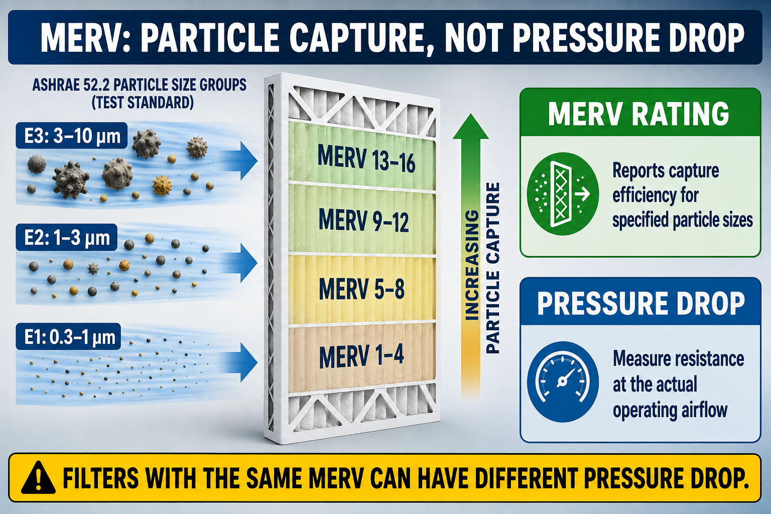
MERV means Minimum Efficiency Reporting Value. It is derived from ANSI/ASHRAE Standard 52.2, which evaluates general-ventilation air-cleaning devices by particle-size efficiency and airflow resistance under defined laboratory conditions. The standard MERV scale runs from 1 through 16; filters more efficient than MERV 16, including HEPA filters, are evaluated and classified using other applicable methods rather than being treated as ordinary higher MERV numbers.
E1: 0.30–1.0 µm
This is the smallest particle-size range used in the MERV calculation. Standard MERV ratings beginning at MERV 13 include specified minimum performance in this range.
E2: 1.0–3.0 µm
This intermediate range becomes increasingly important in the middle and higher MERV ratings and includes many fine airborne particles.
E3: 3.0–10.0 µm
This larger particle-size range is used throughout the MERV scale and includes particle sizes associated with much visible dust, lint fragments, pollen fragments, and similar material.
Higher MERV
A higher MERV rating means better standardized capture performance in the particle-size ranges represented by that rating. It does not mean the filter captures every particle or removes gases and vapors.
Current EPA guidance commonly recommends MERV 13, or the highest efficiency the system fan and filter slot can accommodate, when improved fine-particle filtration is desired. The phrase “can accommodate” requires field evaluation of filter fit, pressure drop, airflow, blower operation, and equipment performance rather than an assumption based only on filter thickness.
MERV addresses particle capture within the Standard 52.2 test method. It does not directly rate removal of gases, odors, carbon monoxide, carbon dioxide, radon, or every biological contaminant, and it does not replace source control, ventilation, humidity control, or specialized air-cleaning equipment.
Two Different Filter Properties
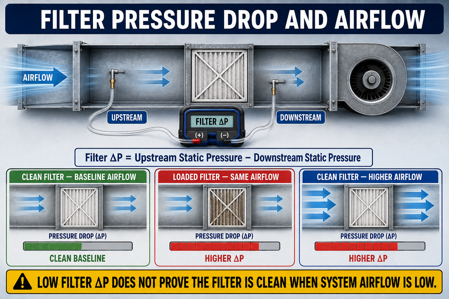
Pressure drop is the difference between static pressure immediately upstream and downstream of the filter or filter assembly. It represents the resistance created as air moves through the media, frame, support structure, and any rack features included between the test points.
ΔP = SPupstream − SPdownstream
Preserve signed readings and follow the airflow direction. A correctly connected differential manometer can display the pressure-drop magnitude directly.
Face Velocity = Airflow ÷ Gross Face Area
More face area lowers average velocity entering the filter at the same system airflow. Pleated-media velocity is also affected by the total media area inside the frame.
Same MERV, Different Drop
Media fiber design, pleat count, pleat spacing, depth, support material, frame construction, and total media area can produce different pressure drops among filters carrying the same MERV rating.
Same Filter, Different Drop
Pressure drop changes with airflow and loading. A catalog value at one airflow cannot be assumed to apply at a different installed airflow.
Higher MERV Is Not Automatically High Drop
A well-designed filter with adequate media area can have lower resistance than a lower-MERV filter with less area or poorer pleat geometry. Compare actual manufacturer data instead of judging by MERV alone.
Low Drop Is Not Automatically Better
A low reading may indicate low system airflow, air bypass around the filter, an incorrectly placed test point, missing media, or a filter that provides less particle capture than the application requires.
Operating without required filtration exposes the blower, heat exchanger, coil, drain system, and ductwork to contamination. Correct the proven cause by addressing filter area, rack design, media selection, loading, bypass, duct resistance, or blower configuration.
Measure the Installed Filter Under Known Conditions
Use the pressure-drop procedures introduced in Lesson 10: Component Pressure Drop and Restriction Diagnosis. The test points must bracket the intended filter or filter assembly, the instrument must be zeroed, and the system configuration must be documented.
Identify the airflow direction.
Trace air from the return grille through the filter toward the blower so upstream and downstream locations are not confused.
Establish the operating condition.
Record mode, fan command, blower setting, active zones, door positions, damper positions, filter identification, and whether the coil is wet or dry when relevant.
Select valid test points.
Place one static-pressure point immediately upstream and one immediately downstream without accidentally including a grille, long transition, coil, or other component unless the combined assembly is intentionally being evaluated.
Measure and calculate.
Connect the higher-pressure point to the positive manometer port and the lower-pressure point to the negative port, or record signed static readings and subtract algebraically.
Determine operating airflow.
Use the correct manufacturer blower-performance data and actual blower configuration, or an appropriate direct airflow method, because pressure drop must be interpreted at airflow.
Compare with valid data.
Use the filter manufacturer’s pressure-drop curve at the operating airflow, approved design data, or a documented clean-filter baseline obtained with the same system configuration.
Pressure taps on opposite sides of an equipment-mounted filter rack may measure the filter, frame, rack openings, access-slot geometry, and nearby transitions together. Label the result “filter-assembly pressure drop” when the test cannot isolate the media and frame alone.
Verify the space behind every drilling location before penetrating sheet metal. After testing, remove tubing and probes, close approved test plugs, secure the filter access, reinstall panels, and confirm that the filter cannot be pulled out of position by blower operation.
More Usable Media Area Can Reduce Resistance
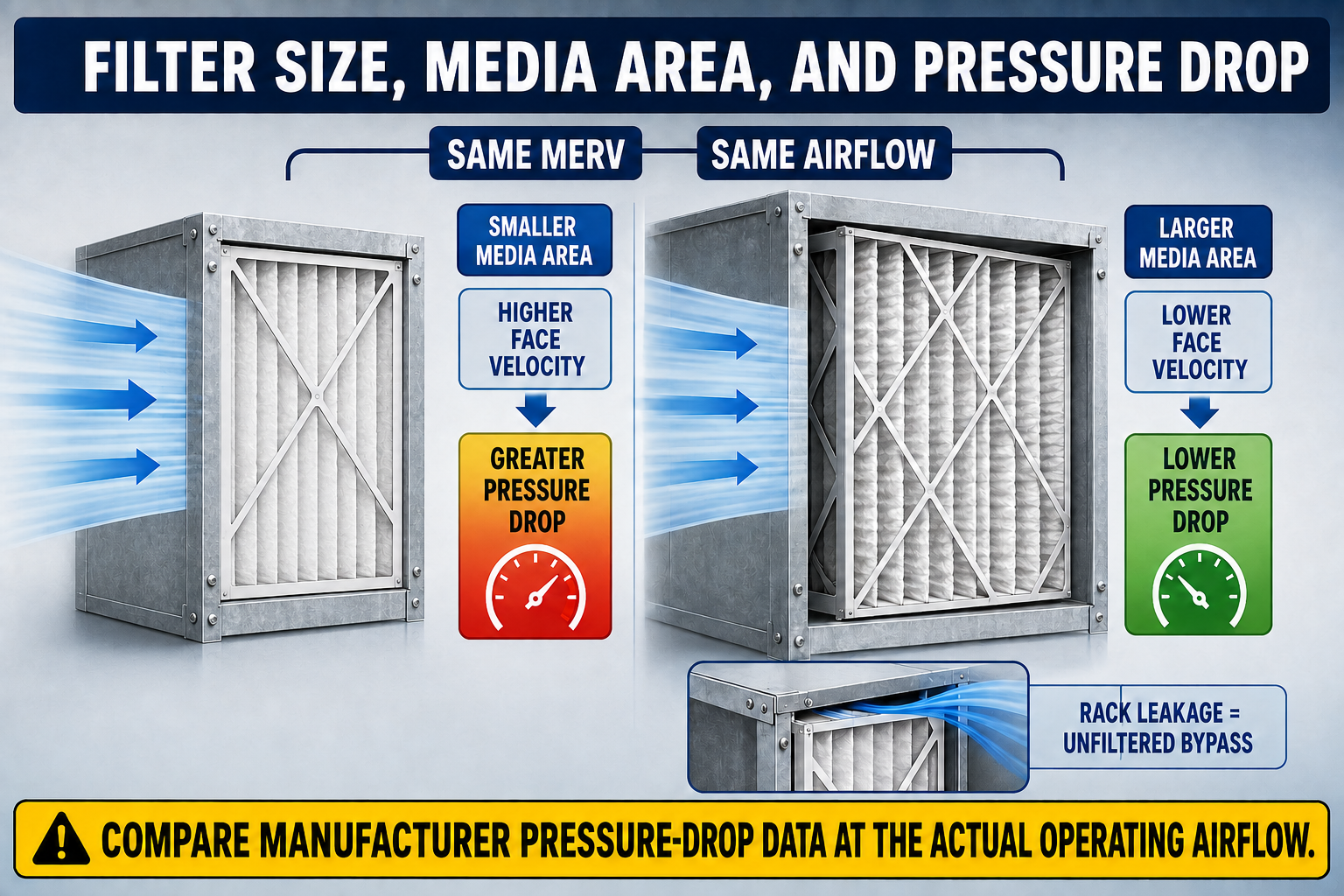
Gross Face Area
A larger filter face or multiple filters arranged in parallel divides the system airflow across more inlet area. This generally reduces face velocity and can reduce pressure drop.
Pleat Depth
A deeper filter can contain more media area and provide better pleat spacing than a shallow filter, but depth alone does not guarantee low resistance. Cabinet transitions and the manufacturer’s tested data still matter.
Usable Media Area
Tightly packed or poorly supported pleats may not use their apparent surface area effectively. Media design, spacers, backing, adhesive, and frame blockage affect the open air path.
Parallel, Not Series
Two filters in separate parallel return paths can increase total face area. Stacking filters one behind another places their resistances in series and should not be done unless the system was specifically designed and evaluated for that arrangement.
Verify the filter’s actual dimensions, airflow direction, frame clearance, rack depth, door closure, and removal path. A filter that must be crushed, bowed, or forced into the rack is not correctly fitted even if its nominal dimensions appear to match.
Pressure Drop Changes as the Filter Collects Material
Particles retained by the media change the filter over time. Loading commonly increases resistance, but the rate of change depends on media design, particle type and concentration, operating hours, airflow, humidity, filter area, and whether air bypasses the media.
Clean Initial Condition
Record the model, size, MERV, installation date, system mode, airflow evidence, and clean filter or filter-assembly pressure drop to establish a useful baseline.
Loaded Condition
Trend pressure drop under comparable operating conditions. A change in blower setting, airflow, zone position, or test location can make two readings appear different even when filter loading is unchanged.
Appearance Is Incomplete Evidence
Media color varies by environment and filter construction. A dark filter may still have acceptable pressure drop, while a filter that looks relatively clean can be restricted by fine material, moisture, or a small effective area.
Time Is Not the Only Criterion
Calendar schedules are convenient, but operating hours and contaminant loading vary widely. Follow manufacturer instructions and use condition, fit, pressure trend, and system performance to support replacement decisions.
Replace wet or damaged disposable media as directed, but also identify the moisture source. Investigate drain problems, air leakage, condensation, outdoor-air entry, rain intrusion, humid-space return leakage, or another defect before returning the system to service.
Installed Efficiency Depends on the Complete Assembly
Frame-to-Rack Gaps
Air follows available pressure differences. Gaps around an undersized filter or a rack without suitable seals allow unfiltered air to bypass the media.
Open Filter Slot
A missing or poorly fitting filter-slot cover can draw mechanical-room, attic, crawlspace, or closet air into a negative-pressure return and can introduce heat, moisture, dust, and odors.
Poor Transition Geometry
Abrupt entries, blocked filter area, small rack openings, internal lips, sharp transitions, or a filter placed too close to the blower inlet can add resistance and create uneven media loading.
Filter Movement
A loose filter can lift, bow, collapse, or pull away from its sealing surface when the blower starts. Correct retainers and support must hold the filter in its intended position without crushing it.
If part of the airflow travels around the filter, less air passes through the media and the measured pressure drop may be lower than expected. Inspect fit and sealing whenever a low reading conflicts with dirt accumulation downstream or poor filtration performance.
Different Blowers Respond Differently to Added Resistance
PSC Blower
As external resistance increases, airflow normally decreases along the selected PSC blower curve. Lower airflow can reduce cooling capacity, promote icing, raise furnace temperature rise, and reduce room delivery.
Constant-Torque ECM
A constant-torque motor may compensate for some added resistance differently from a PSC motor, but it does not guarantee constant airflow and still operates within a finite fan curve and programmed torque range.
Constant-Airflow ECM
A regulating blower may increase speed and power to maintain programmed airflow as resistance rises, until it reaches its operating limit. Acceptable airflow does not prove that filter resistance or fan energy is acceptable.
System-Level Verification
After changing filter type or area, verify TESP, manufacturer blower-table airflow, temperature rise or drop, noise, register delivery, and applicable equipment limits.
A blower-setting change can alter airflow, noise, fan power, motor temperature, cooling performance, humidity removal, and heating temperature rise. Correct excessive filter and return-system resistance before deciding whether the blower configuration should change.
Use a Measured, System-Based Decision
Identify the filtration objective.
Determine whether the priority is equipment protection, general particle reduction, wildfire smoke, occupant sensitivity, a documented indoor-air-quality plan, or another defined need.
Inspect the installed assembly.
Measure the rack, verify actual filter dimensions, inspect seals and transitions, and determine whether additional face area or a deeper media cabinet can be installed correctly.
Record the existing baseline.
Document filter identification, pressure drop, return and supply static, TESP, blower setting, estimated airflow, equipment temperatures, and the current complaint.
Review manufacturer data.
Compare candidate filter pressure-drop curves at the expected airflow and confirm that the cabinet, fan, and equipment can accommodate the resulting operating condition.
Install without bypass.
Follow the airflow arrow, seat the frame against the intended sealing surface, secure retainers, close the access cover, and confirm that the media is not crushed or distorted.
Repeat the complete verification.
Measure filter drop, TESP, blower airflow, cooling or heating temperatures, noise, and room delivery under the same documented conditions used for the baseline.
When improved filtration is required and the existing filter arrangement is restrictive, a properly designed deeper cabinet, larger filter face, or multiple parallel return filters can provide more usable media area. Any modification must maintain correct return geometry, structural support, access, sealing, and blower performance.
Avoid These Filtration and Airflow Mistakes
Choosing by MERV Alone
MERV does not report the installed pressure drop, available media area, rack fit, loading rate, bypass leakage, or the blower’s ability to move the required airflow.
Using a Universal Pressure Limit
Evaluate filter pressure drop with manufacturer data, design information, and actual airflow. A value taken from another filter or system is not a valid pass-or-fail criterion.
Judging Only by Appearance
Color does not establish resistance, efficiency, bypass, moisture condition, or remaining service life. Combine inspection with pressure and system-performance evidence.
Ignoring the Rack
A good filter in a restrictive or leaking rack can still produce poor airflow or poor filtration. Evaluate the complete installed assembly.
Stacking Filters
Adding a second filter in series normally adds resistance and can create service confusion. Use only filtration arrangements intended by the equipment and air-system design.
Stopping After the Filter Fits
Correct physical fit does not prove acceptable operation. Repeat pressure, airflow, temperature, noise, and distribution checks after any meaningful filtration change.
Can You Evaluate an HVAC Filter Correctly?
- What does MERV stand for, and what type of performance does it report?
- What are the three particle-size ranges used by ASHRAE Standard 52.2 for MERV?
- Why does a higher MERV rating not automatically establish higher pressure drop?
- Why can two filters with the same MERV and nominal dimensions have different resistance?
- How is filter pressure drop determined from signed upstream and downstream readings?
- Why must filter pressure drop be interpreted at the actual operating airflow?
- How can increased filter face area reduce resistance?
- Why can deeper pleats reduce pressure drop without guaranteeing that every deep filter will be low resistance?
- How can air bypass cause both poor filtration and an unexpectedly low measured filter drop?
- Why is filter appearance alone an unreliable replacement criterion?
- What system conditions should be documented when establishing a clean-filter baseline?
- How can PSC, constant-torque, and constant-airflow blowers respond differently to added filter resistance?
- Why should filters not be stacked in series unless the system was designed for that arrangement?
- What should be verified after upgrading filter efficiency or changing filter area?
What You Should Have Learned
MERV reports standardized particle-capture performance for particle sizes from 0.3 through 10 micrometers; it is not a direct rating of installed airflow resistance.
Filters with the same MERV can have different pressure drops because media design, pleat geometry, depth, face area, frame construction, and support materials differ.
Filter pressure drop must be measured across valid upstream and downstream locations and interpreted at the actual operating airflow.
Increasing filter face area or usable media area can reduce velocity and resistance, but manufacturer performance data and field verification remain necessary.
Dirt loading, moisture, filter damage, incorrect orientation, poor retainers, rack restrictions, and air bypass can all change installed filter performance.
A low measured filter drop can indicate low resistance, low airflow, bypass leakage, missing media, or poor test locations; it must be interpreted with other evidence.
PSC, constant-torque, and constant-airflow blowers respond differently to added resistance, so airflow and fan operation must be verified for the installed equipment.
A successful filter change maintains filtration integrity while producing acceptable pressure, airflow, equipment temperatures, noise, and room delivery.