Run Capacitors and Dual Run Capacitors
A run capacitor is a continuous-duty AC component that remains connected while an applicable single-phase motor operates. It works with the motor’s auxiliary winding to establish the current relationship required for starting torque, running torque, direction, and normal motor performance.
HVAC/R equipment may use separate run capacitors for the compressor and condenser-fan motor or combine both capacitor sections in one dual run capacitor. Correct service requires understanding the circuit rather than relying on wire color, terminal position, capacitor shape, or memory.
Learning Objectives
Explain Run-Capacitor Operation
Describe how a run capacitor works with the auxiliary winding and why it remains connected during both starting and running.
Trace a PSC Motor Circuit
Distinguish the main-winding branch from the capacitor and auxiliary-winding branch in a permanent split capacitor motor.
Identify Dual Capacitor Sections
Explain the internal relationship among the C, FAN, and HERM terminals of a dual run capacitor.
Apply Safe Service Practices
Use equipment diagrams, capacitor markings, approved replacement information, energy isolation, discharge procedures, and voltage verification.
A Run Capacitor Remains in the Operating Circuit
A conventional run capacitor is a nonpolarized AC capacitor designed for continuous duty within its approved voltage, temperature, frequency, and application limits. It may be used with a compressor, blower motor, condenser-fan motor, evaporator-fan motor, pump, or another applicable single-phase load.
The run capacitor is connected in series with the motor’s auxiliary winding. This capacitor-and-winding path operates as a branch of the complete motor circuit. The main winding forms another branch. Both winding circuits remain energized while a conventional permanent split capacitor motor operates.
| Characteristic | Run Capacitor | Service Significance |
|---|---|---|
| Duty | Designed for continuous operation in an approved circuit. | It remains energized during starting and running rather than being switched out after acceleration. |
| Polarity | Nonpolarized AC component. | Its terminals are not identified as positive and negative. |
| Circuit Location | Connected in series with an auxiliary motor winding. | The capacitor affects auxiliary-winding current and its timing relative to the main-winding current. |
| Capacitance | Selected for a specific motor and circuit design. | An incorrect microfarad value changes current, phase relationship, torque, temperature, and motor performance. |
| Voltage Rating | Marked with an AC voltage rating. | The replacement must have a suitable voltage rating and meet the equipment manufacturer’s requirements. |
| Construction | Commonly enclosed in a round or oval metal case. | Shape and physical size alone do not determine electrical compatibility. |
The Main and Auxiliary Circuits Operate Together
In a simplified PSC motor circuit, the main winding is connected across the supply as one branch. The run capacitor and auxiliary winding are connected in series with each other and form a second branch across the supply. The capacitor changes the electrical characteristics of the auxiliary branch.
During startup, current flows through both winding circuits and helps establish the rotating magnetic effect required for starting direction and torque. After acceleration, both winding circuits remain energized. A conventional PSC motor does not use a centrifugal switch or starting relay to remove the run capacitor.

Power Is Applied
Supply voltage is applied to the main-winding branch and the capacitor-and-auxiliary-winding branch.
Branch Currents Differ
The capacitor changes the impedance and current timing of the auxiliary branch relative to the main-winding branch.
Starting Torque Develops
The physical winding arrangement and separated winding currents establish a rotating magnetic effect and starting direction.
Both Branches Remain Active
The motor accelerates and continues operating with the run capacitor and auxiliary winding still connected.
Review the PSC Motor
For additional coverage of PSC construction, operating sequence, multi-speed blower applications, and motor diagnosis, review Permanent Split Capacitor Motors.
The Capacitance Value Is Part of the Motor Design
The run capacitor, auxiliary winding, main winding, applied voltage, supply frequency, and mechanical load work together as one designed system. Changing the capacitance changes auxiliary-winding current and the phase relationship between the motor’s winding circuits.
The specified capacitance is therefore not an approximate motor-size category. It is an electrical requirement for the particular motor and equipment application. Installing a different value may reduce torque, increase current, cause overheating, create noise, reduce efficiency, or shorten motor and capacitor life.
Starting Performance
An incorrect run capacitor can weaken starting torque and contribute to slow acceleration, humming, overload operation, or failure to start.
Running Performance
Because the capacitor remains connected, an incorrect value can affect current, temperature, torque, speed, noise, and efficiency throughout operation.
Auxiliary-Winding Temperature
An unsuitable capacitance value or voltage condition can produce abnormal auxiliary-winding current and excessive motor heating.
Equipment Performance
Abnormal fan, blower, or compressor operation can affect airflow, refrigerant pressures, cooling capacity, component temperature, and system reliability.
Do Not Increase Capacitance to “Help” a Motor
A larger microfarad value is not a general-purpose method of increasing motor power or correcting a starting problem. Use the capacitance specified by the motor and equipment manufacturer and diagnose the reason the motor is not operating normally.
One Enclosure May Serve One Capacitor Circuit
A single run capacitor contains one capacitor section with two external terminal groups. It may serve a blower motor, condenser-fan motor, evaporator-fan motor, compressor, pump, or another approved load.
Many capacitor terminals provide more than one spade tab at the same electrical point. These additional tabs allow multiple conductors to connect without stacking connectors improperly. The tabs within one terminal group are electrically common, but the two terminal groups are insulated from each other by the capacitor’s internal construction.
Round and Oval Cases
Single run capacitors may use round or oval metal cases. Case shape does not change the basic function and does not establish the correct replacement.
Multiple Spade Tabs
Several tabs may be provided on one terminal group. Tabs within that group are the same electrical connection point.
No Positive or Negative Terminal
A conventional motor-run capacitor is nonpolarized. Either external terminal may be used for either side of its approved AC circuit.
One Marked Capacitance
A single run capacitor normally has one capacitance value, tolerance, AC voltage rating, and set of environmental or safety markings.
Two Run Capacitors Share One Enclosure and One Terminal
A dual run capacitor combines two separate run-capacitor sections in one enclosure. One section normally serves the condenser-fan motor and the other serves the single-phase compressor. The two internal sections share the terminal marked C.
A dual run capacitor does not combine a start capacitor and a run capacitor. Both internal sections are run-capacitor sections intended for continuous duty in their approved circuits.
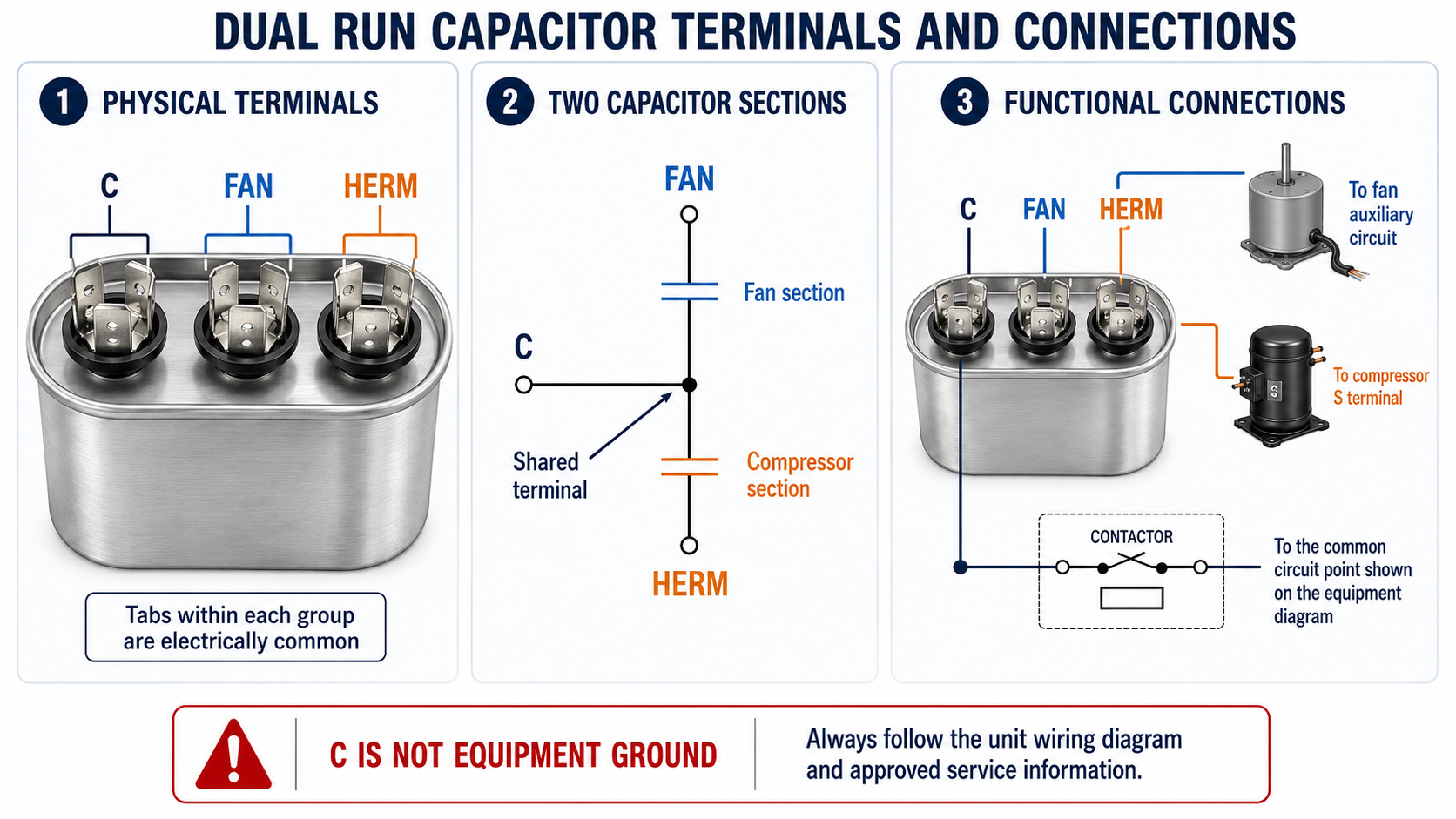
| Terminal | Internal Relationship | Typical Functional Connection | Important Caution |
|---|---|---|---|
| C | Shared terminal for both internal capacitor sections. | Connects to the common circuit point identified on the equipment wiring diagram. | C means the capacitor’s shared terminal. It does not mean chassis ground and should not automatically be treated as the compressor’s C terminal. |
| FAN | Opposite side of the fan capacitor section. | Connects to the applicable condenser-fan motor auxiliary circuit. | Motor lead colors are not universal. Use the wiring diagram and motor information. |
| HERM | Opposite side of the compressor capacitor section. | Normally connects to the start terminal or start-winding circuit of the applicable hermetic compressor. | Confirm the compressor terminals and complete circuit before connecting conductors. |
Each Internal Section Has Its Own Microfarad Rating
A dual run capacitor may be marked 45 + 5 µF, 40/5 µF, or with another two-value format. The larger value commonly identifies the compressor section and the smaller value commonly identifies the fan section, but the actual label and equipment information must control the interpretation.
Example: 45 + 5 µF
The compressor section between C and HERM is rated 45 µF, while the fan section between C and FAN is rated 5 µF.
The Values Are Not Added
The marking does not mean the capacitor should be treated as one 50-µF capacitor. It identifies two separate capacitor sections.
The Plus Sign Is Not Polarity
The plus sign separates the two capacitance ratings. Conventional dual motor-run capacitors are nonpolarized AC components.
Each Section Is Tested Separately
The fan section is evaluated between C and FAN, while the compressor section is evaluated between C and HERM. Safe testing is covered in Lesson 5.
Ratings and Replacement Are Covered in Lesson 4
Capacitance is only one replacement requirement. The AC voltage rating, tolerance, duty, temperature limits, terminal arrangement, physical mounting, safety classification, and manufacturer approval must also be considered.
Follow the Diagram—Not Wire Color or Memory
Capacitor wire colors, terminal positions, and the number of conductors connected to a terminal are not universal. Equipment manufacturers may use different harnesses, motor leads, contactor arrangements, compressor plugs, control modules, and replacement components.
Before disconnecting a capacitor, identify the component, locate the equipment wiring diagram, photograph or document the existing connections, and apply clear conductor labels. Confirm that the existing wiring is correct rather than reproducing a previous error.
Read the Molded or Stamped Markings
Identify C, FAN, and HERM from the markings at the actual terminal groups. Do not identify them only by their physical positions on the case.
Trace Each Conductor
Determine whether each wire connects to the contactor, compressor, fan motor, control module, or another approved circuit point.
Inspect the Connectors
Loose, overheated, corroded, cracked, or poorly fitting quick-connect terminals can create resistance, heat, intermittent operation, and capacitor damage.
Use the Correct Terminal Capacity
Do not force oversized connectors, stack conductors improperly, or modify the capacitor terminals in a way not approved by the equipment manufacturer.
C Does Not Mean Equipment Ground
The C marking identifies the shared terminal of the dual capacitor’s two internal sections. Connecting it to the equipment cabinet merely because it is marked C can create a dangerous short circuit and equipment damage.
Capacitor and Compressor Terminal Letters Describe Different Components
A single-phase hermetic compressor commonly has terminals marked C, S, and R for common, start, and run. A dual run capacitor has terminals marked C, FAN, and HERM. The letter C appears on both components, but it does not describe the same physical terminal or automatically establish a direct C-to-C connection.
The compressor capacitor section is generally connected between the compressor’s start and run circuit points. In a common dual-capacitor arrangement, HERM connects to compressor S while the capacitor C terminal connects to the circuit point associated with the other side of the compressor capacitor section. The equipment wiring diagram must be used to confirm the actual circuit.
Review Hermetic Compressor Terminals
For compressor construction, C-S-R terminal relationships, terminal identification, overload protection, and terminal hazards, review Hermetic Compressor Motors and Terminals.
Run Capacitors Serve Different HVAC/R Loads
| Application | Typical Capacitor Arrangement | Service Considerations |
|---|---|---|
| Condenser-Fan Motor | Separate single run capacitor or FAN section of a dual run capacitor. | Confirm motor capacitance, voltage, wiring, rotation, bearing condition, blade condition, and airflow. |
| Indoor Blower Motor | Separate run capacitor used with an applicable PSC motor. | Confirm selected speed tap, capacitance, supply voltage, blower-wheel condition, airflow, and motor current. |
| Refrigeration Evaporator Fan | Separate run capacitor where required by the motor design. | Consider low-temperature operation, moisture, corrosion, fan-blade condition, and manufacturer requirements. |
| Single-Phase Compressor | Separate run capacitor or HERM section of a dual run capacitor. | Use the compressor model information, wiring diagram, approved capacitance, overload condition, voltage, and starting requirements. |
| Pump or Other PSC Load | Separate run capacitor selected for the particular motor. | Evaluate the driven load, bearings, impeller, voltage, current, environment, and motor nameplate. |
Control Stored Energy Before Handling a Capacitor
A run capacitor may retain hazardous electrical energy after incoming power is disconnected. Equipment may also have multiple power sources, automatically controlled contactors, connected electronic modules, or other stored-energy hazards.
Before touching the capacitor or its conductors, identify and disconnect every power source, apply the required lockout/tagout procedure, verify absence of voltage, follow the equipment or capacitor manufacturer’s approved discharge procedure, and recheck terminal voltage.
Do Not Short the Terminals With a Screwdriver
An uncontrolled short can produce arcing, molten metal, equipment damage, personal injury, and misleading diagnostic results. Use the approved discharge method and properly rated test equipment.
Check Every Terminal Pair
For a dual run capacitor, stored voltage may exist between C and FAN, C and HERM, or other terminal combinations required by the service procedure.
Protect Compressor Terminals
Keep the compressor terminal cover or approved molded plug secured except when an authorized service procedure requires access.
Remove Connectors Correctly
Grip an approved quick-connect terminal by its connector body rather than pulling on the conductor or damaging the capacitor spade.
Restore the Equipment Completely
Secure the capacitor, correct loose connections, reinstall covers and guards, remove tools, and verify safe operating conditions before returning equipment to service.
Run-Capacitor Problems Affect the Complete System
A Fan May Not Start
An unsuitable or failed fan capacitor section may contribute to humming, slow starting, unreliable operation, overheating, overload operation, or failure to run.
A Compressor May Not Start
An unsuitable or failed compressor capacitor section may contribute to high starting current, protector operation, humming, or failure to accelerate.
One Dual Section May Fail
The compressor section and fan section are separate internal capacitors. One section may test outside its rating while the other remains within its marked tolerance.
The Capacitor May Not Be the Root Cause
Low voltage, loose connections, damaged windings, defective controls, mechanical binding, excessive load, poor airflow, or incorrect replacement parts can produce similar symptoms or contribute to capacitor failure.
Avoid These Errors
“A Dual Run Capacitor Contains a Start and Run Capacitor”
A conventional dual run capacitor contains two run-capacitor sections: one commonly used for the compressor and one commonly used for the condenser-fan motor.
“C Means Compressor Common”
On a dual run capacitor, C identifies the shared terminal of the two capacitor sections. It is not automatically the compressor’s common terminal.
“C Means Ground”
The C terminal is an energized circuit connection, not chassis ground. Connecting it to the cabinet can create a direct electrical fault.
“FAN and HERM Are Connected Together”
FAN and HERM connect to separate internal capacitor sections. Each section connects to C, but FAN and HERM are not directly connected internally.
“Wire Colors Identify Every Terminal”
Wire colors vary among equipment and replacement components. Use the capacitor markings, equipment diagram, and traced connections.
“Any Close Microfarad Value Will Work”
The specified capacitance is part of the motor design. Use the required value and approved replacement information rather than selecting a value that merely appears close.
Review Questions
1. What is the defining duty characteristic of a run capacitor?
Answer: A run capacitor is designed to remain connected continuously while the applicable motor operates within its approved conditions.
2. How are the two branches of a simplified PSC motor circuit arranged?
Answer: The main winding forms one branch across the supply, while the run capacitor and auxiliary winding are connected in series with each other and form a second branch across the supply.
3. Is the run capacitor removed after a PSC motor accelerates?
Answer: No. The run capacitor and auxiliary winding remain connected during starting and running.
4. What two capacitor sections are contained in a conventional dual run capacitor?
Answer: It contains a fan run-capacitor section and a compressor run-capacitor section.
5. Which terminal is shared by the two internal sections of a dual run capacitor?
Answer: The terminal marked C is shared by the fan and compressor capacitor sections.
6. Between which terminals is the fan capacitor section connected?
Answer: The fan capacitor section is connected between C and FAN.
7. Between which terminals is the compressor capacitor section connected?
Answer: The compressor capacitor section is connected between C and HERM.
8. Does capacitor C mean the same thing as compressor C?
Answer: No. Capacitor C identifies the shared terminal of the two capacitor sections, while compressor C identifies the common terminal of the compressor motor windings.
9. What does a 45 + 5 µF dual capacitor marking mean?
Answer: It identifies a 45-µF compressor section and a separate 5-µF fan section. The values are not added and the plus sign is not a polarity marking.
10. Why should a technician avoid relying on wire color when replacing a capacitor?
Answer: Wire colors are not universal and may vary among equipment, motors, compressors, harnesses, and replacement components. The actual diagram, terminal markings, and traced circuit must be used.
Lesson 2 Summary
- A run capacitor is a nonpolarized AC component designed for continuous duty in an approved circuit.
- The run capacitor remains connected during both starting and running.
- In a simplified PSC motor, the main winding forms one branch across the supply.
- The run capacitor and auxiliary winding are connected in series with each other and form another motor branch.
- The capacitor changes auxiliary-winding current and its timing relative to the main-winding current.
- The specified capacitance is part of the motor and equipment design.
- An incorrect capacitance can affect torque, current, temperature, noise, efficiency, acceleration, and equipment performance.
- A single run capacitor contains one capacitor section and two terminal groups.
- A dual run capacitor contains two continuous-duty run-capacitor sections in one enclosure.
- The fan section is connected between C and FAN.
- The compressor section is connected between C and HERM.
- The C terminal is shared by both capacitor sections and is not equipment ground.
- Capacitor C and compressor C describe different component terminals.
- A dual capacitance marking identifies two separate microfarad values rather than one combined value.
- Wire colors, terminal positions, and circuit arrangements are not universal.
- Technicians must use the nameplate, capacitor markings, equipment diagram, compressor information, and approved service literature.
- A run capacitor may retain hazardous stored energy after external power is disconnected.
- Safe service requires energy isolation, approved discharge procedures, and voltage verification.
- A capacitor symptom does not prove that the capacitor is the root cause of the equipment problem.