Start Capacitors and Start-Assist Components
A start capacitor is an intermittent-duty AC component used to increase the phase separation and starting torque of an applicable single-phase motor or compressor. It is energized only during startup and must be removed from the circuit after the motor accelerates.
Starting relays, electronic switches, and manufacturer-approved start-assist modules control when the start capacitor is connected. These components are not universal: their capacitance, voltage rating, duty, switching characteristics, wiring, and application must match the motor, compressor, and equipment requirements.
Learning Objectives
Explain Start-Capacitor Operation
Describe how a start capacitor increases phase separation and starting torque during motor acceleration.
Trace the Starting Sequence
Follow the circuit from stopped condition through acceleration and removal of the start capacitor.
Compare Starting Controls
Explain how potential relays and electronic start-assist devices connect and disconnect a start capacitor.
Apply and Diagnose Start Assist
Recognize application requirements, common failure patterns, and the need to diagnose the complete starting circuit.
A Start Capacitor Provides Additional Starting Torque
A single-phase motor requires a method of establishing starting direction and torque. In a capacitor-start circuit, the start capacitor is connected in series with the motor’s start or auxiliary winding during acceleration. The capacitor changes the impedance and current timing of that winding circuit relative to the main or run winding.
Start capacitors commonly have greater capacitance than run capacitors serving comparable motor applications. This greater capacitance can produce stronger phase separation and higher starting torque, but it also results in an operating condition that the capacitor and start winding are not designed to sustain continuously.
| Characteristic | Start Capacitor | Run Capacitor |
|---|---|---|
| Primary Function | Provides additional phase shift and torque during startup. | Supports the designed winding-current relationship during starting and running. |
| Duty | Intermittent duty for a limited starting period. | Continuous duty in an approved operating circuit. |
| Time in Circuit | Removed after the motor accelerates. | Remains connected while the applicable motor operates. |
| Typical Capacitance | Often substantially higher than a run capacitor used with a similar motor. | Selected for continuous motor operation and commonly lower than start capacitance. |
| Typical Construction | Commonly housed in a black plastic or phenolic cylindrical case. | Commonly housed in a round or oval metal case. |
| Switching Requirement | Requires an approved relay, switch, or electronic device to remove it after startup. | Does not require removal from a conventional PSC operating circuit. |
The Capacitor Is Used Only During Acceleration
Before startup, the starting-control contacts are normally positioned so the start capacitor will be available when power is applied. When the motor circuit is energized, current flows through the main or run winding and through the start-capacitor and start-winding circuit.
As the rotor or compressor motor accelerates, the starting control responds to current, voltage, time, temperature, motor speed, or another designed operating characteristic. The control then opens or switches electronically to remove the start capacitor from the circuit.
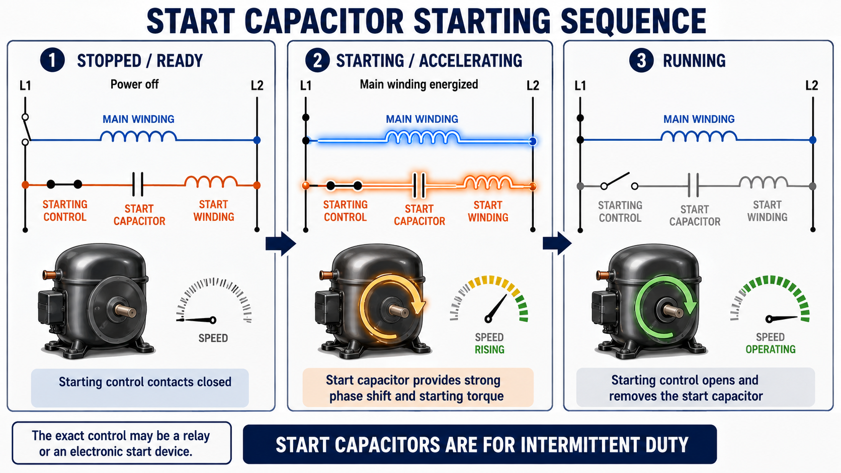
Stopped and Ready
The motor is de-energized and stationary. The starting-control circuit is positioned to connect the start capacitor when a starting attempt begins.
Starting Circuit Energizes
Power is applied to the motor, and the start capacitor operates in series with the start or auxiliary winding.
Starting Torque Accelerates the Motor
The capacitor and winding relationship produces the torque needed to accelerate the motor and connected mechanical load.
The Start Capacitor Is Removed
The starting control opens or switches off the temporary capacitor path while the motor continues running through its designed operating circuit.
Failure to Remove the Start Capacitor Can Be Destructive
A start capacitor left energized too long can overheat, swell, vent, leak, or rupture. The start winding and starting-control components may also overheat or fail.
CSIR and CSCR Motors Use Different Running Arrangements
A capacitor-start induction-run motor uses a start capacitor and start winding during acceleration. After startup, the starting control removes the start capacitor and start-winding circuit, and the motor continues operating through its run winding.
A capacitor-start, capacitor-run motor uses both start and run capacitance. During startup, the circuit provides the larger capacitance needed for high starting torque. After acceleration, the start capacitor is removed while the run capacitor and applicable auxiliary-winding circuit remain energized.
| Motor Circuit | During Startup | After Acceleration | Common Application Consideration |
|---|---|---|---|
| CSIR | Start capacitor and start winding assist acceleration. | Start capacitor and start winding are removed; the motor runs through the main winding. | Provides higher starting torque than a basic split-phase design. |
| CSCR | Start and run capacitance support the starting circuit. | Start capacitor is removed; run capacitor remains in the operating circuit. | Provides high starting torque while maintaining a capacitor-assisted running circuit. |
| PSC With Added Start Assist | An approved temporary start-capacitor branch supplements the existing run-capacitor circuit. | The start-assist branch is removed; the original run capacitor remains connected. | Start assist must be approved for the particular compressor and equipment. |
Review the Motor Circuits
For additional coverage of CSIR and CSCR winding relationships, operating sequences, and compressor applications, review Capacitor-Start Motors: CSIR and CSCR.
The Control Determines When the Capacitor Is Connected
Different motors and compressors use different methods to control the start capacitor. The selected control must close or conduct reliably during startup and remove the capacitor at the correct point in the acceleration sequence.
Potential Relay
A potential relay responds to voltage developed across the start-winding circuit as the motor accelerates. Its normally closed contacts open to remove the start capacitor.
Current Relay
A current relay responds to high starting current. Its contacts connect the start circuit during the high-current starting period and change state as motor current falls.
PTC Starting Device
A positive-temperature-coefficient device initially conducts current and then increases resistance as it heats, reducing current through the start-capacitor circuit.
Electronic Start Device
An electronic control monitors an electrical or timing condition and switches the start capacitor into and out of the circuit without conventional mechanical relay contacts.
Centrifugal Switch
An accessible motor may use a speed-operated centrifugal mechanism to open the start circuit after acceleration. This arrangement is not installed inside a conventional hermetic compressor shell.
Manufacturer-Specific Module
Some compressors use approved starting modules with programmed control, protection, or diagnostic functions. Their wiring and operation must be taken from the applicable service information.
Rising Start-Winding Voltage Opens the Contacts
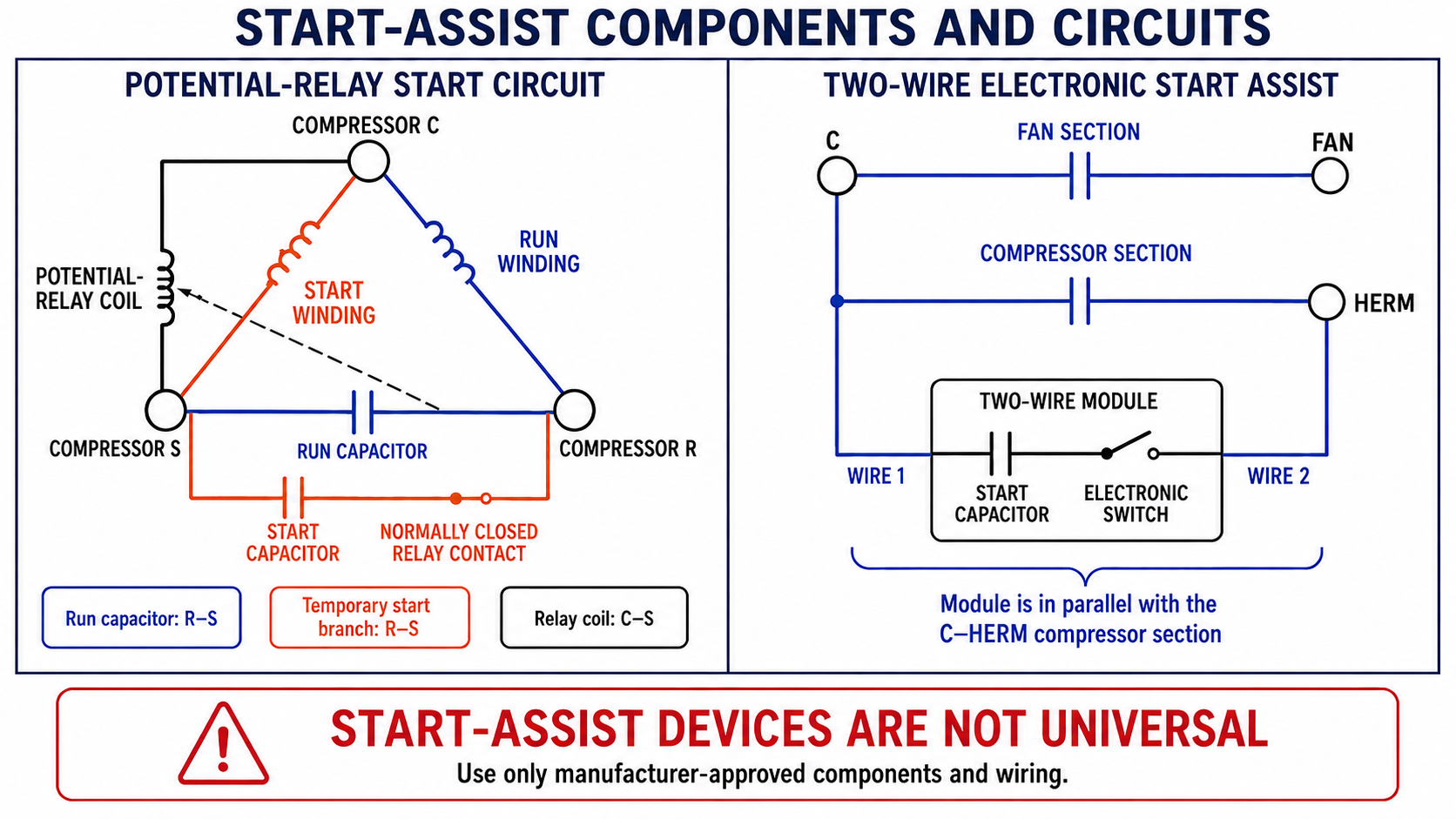
A potential relay is commonly used in capacitor-start compressor circuits. Its normally closed contact is connected in series with the start capacitor. Before startup and during the early part of acceleration, the closed contact allows the start capacitor to operate.
The potential-relay coil is connected across the compressor start-winding circuit, commonly between compressor S and C. As the compressor accelerates, voltage generated across the start winding rises. When this voltage reaches the relay’s designed pickup level, the coil opens the normally closed contact and removes the start capacitor.
After the compressor stops and the start-winding voltage falls, the relay releases and its contact returns to the normally closed position, preparing the circuit for the next starting attempt.
Contacts Are Closed
With the compressor stopped, the potential-relay contact is normally closed and the start capacitor is available.
The Compressor Accelerates
The start capacitor provides additional starting assistance while start-winding voltage rises with motor speed.
The Relay Picks Up
At the designed voltage, the potential-relay coil opens the contact in series with the start capacitor.
The Relay Resets After Shutdown
When the compressor stops and coil voltage falls, the contact returns to its normally closed position.
Potential Relays Are Not Selected by Appearance
Coil characteristics, pickup and dropout values, contact ratings, mounting, terminal identification, and compressor application must match the approved starting circuit. Relays that look alike may not operate at the same electrical values.
Different Devices May Provide Temporary Start Capacitance
A conventional potential-relay circuit and a two-wire electronic start-assist device can both provide temporary start capacitance, but they do not use the same switching method or selection procedure.
| Characteristic | Potential-Relay Circuit | Two-Wire Electronic Start Assist |
|---|---|---|
| Start Capacitor | Separate capacitor selected for the compressor and relay circuit. | Commonly contained within the sealed start-assist module. |
| Switching Method | Normally closed mechanical contact operated by a voltage-sensing relay coil. | Electronic or solid-state switching method within the module. |
| Control Response | Responds to start-winding voltage as the motor accelerates. | Responds according to the module’s internal design and approved application. |
| Common Connection | Start capacitor and relay contact form a temporary branch in the compressor starting circuit. | Approved two-wire devices may connect across C and HERM on a dual run capacitor. |
| Replacement | Capacitor and relay must match the required electrical characteristics. | The complete module is commonly replaced as an assembly. |
Application Depends on the Compressor and Equipment Design
Some compressors include start components as part of the original equipment design. Other PSC compressors may allow or require an approved start-assist device for particular applications, starting conditions, or equipment configurations.
A start-assist device should not be installed merely because a compressor does not start. Low voltage, damaged wiring, loose connections, defective contactors, incorrect run capacitance, open windings, overload operation, pressure imbalance, mechanical compressor damage, or an unsuitable power supply must be investigated.
Original Equipment Requirement
If the compressor or equipment was designed with a start capacitor and relay, use the specified components and wiring.
Approved Field Application
Some manufacturers permit a listed start-assist assembly for an identified compressor model or equipment application.
Low-Voltage Starting Condition
Start assist may improve torque in an approved application, but it does not eliminate the need to correct inadequate supply voltage or excessive conductor voltage drop.
Pressure and Restart Conditions
Equipment controls may require an off-cycle delay or pressure-equalization period before restarting. Start assist should not be used to defeat required control timing.
Do Not Use Start Assist to Force a Defective Compressor to Run
A start-assist device cannot repair damaged windings, a seized mechanism, an open overload, an incorrect run capacitor, a failed contactor, or an inadequate power supply. Diagnose and correct the root cause.
Start Capacitors Have Application-Specific Requirements
A start capacitor may be marked with a capacitance range rather than one exact nominal value. It also has an AC voltage rating, duty or cycle limitation, temperature limits, case dimensions, and terminal arrangement.
The correct capacitor must be selected from the motor, compressor, relay, or equipment manufacturer’s information. A capacitor that physically fits or has a similar capacitance range may still have an unsuitable voltage rating, duty, terminal arrangement, or starting application.
Capacitance Range
A start capacitor may be marked with a range such as two microfarad values separated by a dash. Both limits are part of the specified range.
AC Voltage Rating
The marked VAC value is a component rating. The replacement must meet the approved circuit and manufacturer requirements.
Intermittent Duty
The start capacitor is designed for limited energization and specified starting cycles rather than continuous operation.
Physical and Terminal Requirements
The case, mounting, terminals, protective cover, wiring, and environmental conditions must be suitable for the equipment.
Detailed Replacement Requirements Are Next
Lesson 4 examines capacitance, tolerance, voltage rating, frequency, temperature, duty, terminals, mounting, documentation, and approved replacement selection in detail.
The Capacitor, Control, and Motor Affect One Another
| Condition | Possible Result | Diagnostic Direction |
|---|---|---|
| Start Capacitor Open or Low in Capacitance | Weak starting torque, humming, slow acceleration, or failure to start. | Safely test the capacitor and verify the complete starting circuit, voltage, windings, and load. |
| Start Capacitor Shorted | High current, protective-device operation, damaged contacts, or failure to start. | Isolate power and inspect the capacitor, relay, wiring, motor, and protective devices. |
| Relay Contact Stuck Open | The start capacitor is unavailable during the starting attempt. | Check relay contacts, coil circuit, terminal connections, and approved relay characteristics. |
| Relay Contact Stuck Closed | The start capacitor remains energized and may overheat, vent, or rupture. | De-energize the equipment and evaluate the capacitor, relay, start winding, wiring, and overload condition. |
| Potential-Relay Coil Open | The contact may remain closed and fail to remove the start capacitor. | Follow manufacturer procedures for coil resistance, terminal identification, and relay replacement. |
| Incorrect Relay or Start Device | Premature removal, delayed removal, repeated cycling, or failure to connect the start capacitor. | Compare the complete device identification and electrical specifications with approved information. |
| Motor Does Not Accelerate | The starting control may keep the capacitor energized longer than intended. | Investigate supply voltage, run capacitance, windings, overload, mechanical load, system pressures, and compressor condition. |
Start Capacitors Can Store Hazardous Energy
A start capacitor may retain hazardous voltage after power is disconnected. The equipment may also contain a run capacitor, dual run capacitor, electronic control, crankcase heater, control transformer, or another energy source.
Identify and disconnect every power source, apply the required lockout/tagout procedure, verify absence of voltage, follow the manufacturer’s approved discharge method, and verify terminal voltage again before handling the capacitor or starting components.
A Failed Start Capacitor May Rupture
Do not stand directly over a swollen, leaking, overheated, or suspect capacitor. Keep unnecessary personnel away, use required protective equipment, and follow the approved procedure for de-energizing, verifying, removing, and disposing of the component.
Never Short With a Screwdriver
An uncontrolled short can create arcing, molten metal, equipment damage, personal injury, and misleading test results.
Protect Hermetic Terminals
Keep approved compressor terminal covers and molded plugs secured except when authorized procedures require access.
Document Before Disconnecting
Photograph and label wires, identify relay terminals, and compare the existing circuit with the equipment diagram.
Replace Damaged Connections
Loose, overheated, corroded, or poorly fitting terminals must be corrected rather than reconnected to the replacement capacitor or relay.
Avoid These Errors
“The Start Capacitor Stays Connected”
A start capacitor is an intermittent-duty component and must be removed after the motor accelerates.
“A Start Capacitor Can Replace a Run Capacitor”
Start and run capacitors have different construction and duty requirements. They are not interchangeable.
“Any Hard-Start Kit Fits Any Compressor”
Start-assist devices have specific capacitance, voltage, switching, wiring, and compressor application requirements.
“A Larger Start Capacitor Is Better”
Excessive capacitance changes starting current and torque and can damage the motor, capacitor, relay, or compressor terminals.
“A Hard-Start Kit Repairs Low Voltage”
Start assist does not correct an inadequate supply, excessive voltage drop, loose connection, or defective contactor.
“Replacing the Capacitor Completes the Repair”
The starting relay, run capacitor, wiring, compressor windings, overload, supply voltage, and mechanical condition must also be evaluated.
Review Questions
1. What is the primary purpose of a start capacitor?
Answer: A start capacitor provides additional phase separation and starting torque while an applicable single-phase motor accelerates.
2. Is a start capacitor designed for continuous operation?
Answer: No. A start capacitor is an intermittent-duty component that must be removed after startup.
3. What happens to the start capacitor after the motor accelerates?
Answer: A relay, switch, or electronic starting control removes the start capacitor from the circuit.
4. What remains energized after startup in a CSCR motor?
Answer: The start capacitor is removed, while the run capacitor and applicable auxiliary-winding circuit remain energized.
5. What is the normal position of a potential relay’s start-capacitor contact when the compressor is stopped?
Answer: The contact is normally closed so the start capacitor is available for the next starting attempt.
6. What causes a potential relay to open its normally closed contact?
Answer: Rising voltage across the start-winding circuit energizes the potential-relay coil as the compressor accelerates.
7. What may happen if the potential-relay contact remains closed?
Answer: The start capacitor may remain energized, overheat, swell, vent, leak, or rupture, and the start winding may also overheat.
8. Where may an approved two-wire electronic start-assist device connect on a dual run capacitor?
Answer: A device designed for that arrangement may connect across C and HERM, in parallel with the compressor run-capacitor section.
9. Why are start-assist devices not universal?
Answer: Their capacitance, voltage rating, switching characteristics, wiring, duty, and compressor application must match the approved equipment requirements.
10. What should be checked when a compressor still does not start with start assist?
Answer: Check the supply voltage, voltage drop, contactor, connections, run capacitor, start components, overload, windings, system pressures, mechanical condition, and manufacturer diagnostic information.
Lesson 3 Summary
- A start capacitor is a nonpolarized AC component used to provide additional starting torque.
- The start capacitor is connected in series with the start or auxiliary winding during acceleration.
- Start capacitors commonly have greater capacitance than run capacitors used in comparable motor applications.
- A start capacitor is designed for intermittent rather than continuous duty.
- The start capacitor must be removed after the motor accelerates.
- A CSIR motor removes the start-capacitor and start-winding circuit after acceleration.
- A CSCR motor removes the start capacitor but keeps the run capacitor and applicable auxiliary circuit energized.
- Starting controls may respond to voltage, current, temperature, time, speed, or another designed characteristic.
- A potential relay uses a normally closed contact in series with the start capacitor.
- The potential-relay coil responds to voltage developed across the start-winding circuit.
- Rising start-winding voltage causes the potential relay to remove the start capacitor.
- An approved two-wire electronic start-assist device may connect across C and HERM on a dual run capacitor.
- Start capacitors, relays, and electronic start devices are application-specific and are not universal.
- A start-assist device should not be used to conceal low voltage, defective controls, damaged windings, or mechanical compressor failure.
- A relay contact stuck closed can leave the start capacitor energized and cause destructive overheating.
- A relay contact stuck open can prevent the start capacitor from assisting the motor.
- Start-capacitor diagnosis must include the control, run capacitor, supply, windings, overload, connections, and mechanical load.
- Start capacitors may retain hazardous electrical energy after power is disconnected.
- Safe service requires isolation, lockout/tagout, approved discharge procedures, and voltage verification.