Capacitor Ratings, Selection, and Replacement
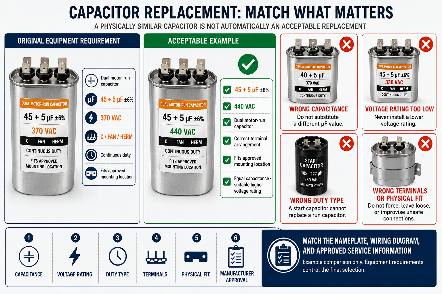
A replacement capacitor must do more than fit inside the electrical compartment. Its capacitance, voltage rating, capacitor type, duty, terminal arrangement, and application must match the requirements of the equipment it serves.
This lesson explains how to read common HVAC/R capacitor markings, compare a replacement with the original component and equipment specifications, and avoid substitutions that can damage motors, compressors, starting components, or wiring.
Learning Objectives
Read Capacitor Markings
Identify capacitance, tolerance, voltage, frequency, temperature, terminal, and duty information printed on common HVAC/R capacitors.
Use Equipment Specifications
Confirm the required capacitor from the unit wiring diagram, parts information, motor label, compressor data, or other manufacturer-approved documentation.
Select a Correct Replacement
Compare capacitance, voltage rating, capacitor type, duty, physical size, terminals, and environmental requirements before installation.
Avoid Unsafe Substitutions
Recognize why an incorrect microfarad value, insufficient voltage rating, wrong capacitor type, or improvised mounting arrangement is unacceptable.
The Markings Describe the Capacitor’s Intended Use
HVAC/R capacitors normally display their capacitance in microfarads, written as µF or MFD, and their maximum operating voltage in volts AC, written as VAC. Run capacitors commonly include a capacitance tolerance, while start capacitors normally show a capacitance range because their application is different.

| Marking | Meaning | Why It Matters |
|---|---|---|
| µF or MFD | Capacitance in microfarads. | The replacement must provide the capacitance specified for the circuit. Do not select a different value merely because it is physically available. |
| Capacitance Range | A start capacitor may be marked with a range such as 189–227 µF. | The complete range is part of the start-capacitor specification and must agree with approved service information. |
| Tolerance | The permitted manufacturing variation from the marked capacitance, commonly shown as a percentage. | Tolerance helps determine the acceptable measured range but does not authorize choosing a different nominal rating. |
| VAC | The capacitor’s AC voltage rating. | The rating must meet the application requirement. A capacitor with a lower voltage rating must not be installed. |
| 50/60 Hz | The supply frequency or frequencies for which the capacitor is rated. | The rating must be suitable for the equipment’s electrical supply and intended application. |
| Temperature Rating | The allowable operating or case-temperature range stated by the manufacturer. | Electrical compartments can become hot, so the replacement must be suitable for the expected environment. |
| C, FAN, and HERM | Terminal identifications on a dual run capacitor. | They identify common, fan-motor capacitance, and hermetic-compressor capacitance connections. They are not interchangeable. |
Nominal Rating and Measured Value Are Different Ideas
The nominal capacitance is the value selected by the equipment or motor manufacturer for the circuit. Tolerance describes how far the actual capacitance may vary from that nominal value and still meet the capacitor manufacturer’s rating. For example, a 40 µF capacitor marked ±5% has a labeled range of 38 to 42 µF.
Example: 7.5 µF ±6%
Six percent of 7.5 µF is 0.45 µF. The labeled tolerance range is therefore 7.05 to 7.95 µF.
Example: 45 µF ±5%
Five percent of 45 µF is 2.25 µF. The labeled tolerance range is therefore 42.75 to 47.25 µF.
Do Not Use Tolerance to Choose a Different Nominal Rating
A 40 µF capacitor that is allowed to measure as high as 42 µF is still a 40 µF capacitor. The tolerance does not make a 42.5 µF replacement equivalent to the specified 40 µF component.
The Voltage Rating Is a Limit, Not the Applied Voltage
A capacitor marked 440 VAC is designed for use within its specified AC voltage limit; the marking does not mean that 440 volts will always be measured across it. The actual capacitor voltage depends on the circuit and operating conditions and may differ from the equipment line voltage.
A replacement must never have a voltage rating lower than the rating required by the equipment manufacturer. Some approved replacement guidance permits a capacitor with the same capacitance and a higher VAC rating, such as replacing a specified 370 VAC run capacitor with an otherwise suitable 440 VAC unit. This must not be treated as a universal substitution rule because application approval, capacitor type, physical fit, terminals, temperature, and other specifications still matter.
| Proposed Replacement | General Evaluation | Required Action |
|---|---|---|
| Same µF and same VAC | May be suitable if all other specifications agree. | Confirm capacitor type, duty, tolerance, terminals, temperature rating, physical fit, and manufacturer approval. |
| Same µF and higher VAC | May be suitable in applications that permit the higher rating. | Verify approved service information and every other replacement requirement before installation. |
| Same µF and lower VAC | Not acceptable. | Obtain a capacitor with the required voltage rating. |
| Different µF | Not a correct replacement unless specifically authorized by the equipment or motor manufacturer. | Use the specified nominal capacitance rather than improvising a substitute. |
Verify the Application Before Matching the Part
The original capacitor label is useful, but it may be unreadable, previously replaced with the wrong part, or inconsistent with a replacement motor. The technician should identify the component served and verify the required rating from current manufacturer documentation for that equipment, motor, compressor, or approved service replacement.
Identify the Load and Circuit
Determine whether the capacitor serves a compressor, condenser fan, indoor blower, pump, or another load and whether it is a run capacitor, start capacitor, or part of a complete start-assist assembly.
Find the Required Specification
Use the unit wiring diagram, service literature, parts information, motor label, compressor data, or approved replacement instructions to establish the correct requirements.
Compare Every Rating
Verify capacitance, tolerance, voltage, frequency, capacitor type, duty, temperature rating, terminals, approvals, and any start-device compatibility requirements.
Verify Fit and Installation
Confirm that the capacitor can be securely mounted, that terminals have safe clearance, and that the wiring can be returned to the documented connections without strain or exposed conductors.
Both Capacitance Sections Must Be Correct
A dual run capacitor contains two capacitor sections in one enclosure. A marking such as 45/5 µF identifies two separate nominal values: 45 µF for the HERM section and 5 µF for the FAN section. The C terminal is common to both internal sections.
| Terminal Pair | Capacitance Section | Example for a 45/5 µF Capacitor |
|---|---|---|
| C to HERM | Compressor run-capacitor section. | Nominally 45 µF. |
| C to FAN | Fan-motor run-capacitor section. | Nominally 5 µF. |
| FAN to HERM | Not the normal terminal pair for directly checking either marked section. | Do not interpret this measurement as either the 45 µF or 5 µF rating. |
A dual run capacitor should normally be replaced with the specified dual unit. If manufacturer-approved service information permits two separate run capacitors, each must have the correct rating, each must be securely mounted, and the documented common and load connections must be preserved. Loose capacitors, unsupported wiring, and improvised terminal arrangements are not acceptable repairs.
Terminal Position Is Not a Reliable Wiring Guide
Terminal locations can differ among capacitor brands and case styles. Read the C, FAN, and HERM markings on the replacement and transfer conductors according to identification and the equipment wiring diagram, not according to where a terminal happens to be located.
Match the Complete Starting Application
A start capacitor is designed for intermittent duty and is not interchangeable with a continuously rated run capacitor. Its microfarad range, voltage rating, duty, and compatibility with the starting control must match an approved application. A complete start-assist kit must also be appropriate for the compressor and system on which it is installed.
Start Capacitor
Verify the specified capacitance range, voltage rating, intermittent-duty application, case style, and terminal arrangement.
Starting Control
Verify the correct potential relay, current relay, PTC device, electronic control, or manufacturer-specified starting device.
Complete Kit
Use an approved combination of components rather than assembling unrelated parts whose pickup, dropout, timing, resistance, or duty characteristics may not match.
A Correct Part Must Also Be Installed Correctly
Before touching a capacitor or its wiring, follow the equipment manufacturer’s service instructions, disconnect all power sources, apply required lockout/tagout procedures, and verify absence of voltage with a properly rated meter. A capacitor may retain stored electrical energy after power has been removed, so use the manufacturer-specified discharge method and verify the voltage before handling the terminals.
Do Not Discharge a Capacitor With a Screwdriver
Shorting capacitor terminals with a screwdriver can produce an arc, damage the terminals or tool, leave the capacitor incompletely discharged, and expose the technician to injury. Use an approved resistive discharge method and confirm the result with a meter.
| Installation Check | Acceptable Condition |
|---|---|
| Mounting | The capacitor is firmly secured with an appropriate bracket or mounting method and cannot move into wiring or grounded metal. |
| Terminal Connections | Connectors fit tightly, conductors are on the correct identified terminals, and no damaged or overheated connector is reused. |
| Clearance | Terminals and conductors have safe clearance from panels, sharp edges, moving parts, and other energized components. |
| Wiring | Connections agree with the equipment diagram and any replacement-motor or approved kit instructions. |
| Final Inspection | All covers, barriers, grounding connections, and access panels are restored before operation. |
A Part That Looks Similar May Still Be Wrong
Matching Only the Case
Capacitors with similar metal or plastic cases may have very different electrical ratings and duty classifications.
Trusting an Old Replacement
The installed capacitor may already be incorrect. Confirm the application from authoritative equipment or component information.
Using a Lower VAC Rating
A lower voltage rating reduces the capacitor’s designed voltage margin and is not an acceptable replacement.
Choosing a Nearby µF Value
A convenient value from truck stock is not a substitute for the nominal capacitance specified by the manufacturer.
Confusing Start and Run Types
Start and run capacitors have different construction and duty requirements and must not be interchanged.
Ignoring the Replacement Motor
A replacement motor may require a different run capacitor from the original motor even when installed in the same equipment.
Check Your Understanding
1. What does µF identify on a capacitor?
It identifies capacitance in microfarads.
2. What does MFD mean on an HVAC/R capacitor?
In this application, MFD is an older marking for microfarads and represents the same unit as µF.
3. What is the labeled acceptable range of a 40 µF capacitor rated ±5%?
The range is 38 to 42 µF.
4. Does a ±5% tolerance permit replacing a specified 40 µF capacitor with a nominal 42.5 µF capacitor?
No. Tolerance describes permitted variation around the specified nominal value; it does not authorize selecting a different nominal rating.
5. May a capacitor with a lower VAC rating replace the specified capacitor?
No. The replacement must meet the required voltage rating and must not have a lower rating.
6. Is a higher VAC rating always an automatically approved replacement?
No. It may be suitable when permitted, but capacitance, type, duty, physical fit, temperature, terminals, and manufacturer approval must also be verified.
7. What do the numbers in a 45/5 µF dual run capacitor identify?
They identify a 45 µF compressor section between C and HERM and a 5 µF fan section between C and FAN.
8. Why should the old capacitor label not be the only replacement reference?
The label may be unreadable or the installed capacitor may already be incorrect, so the requirement should be verified from current equipment, motor, compressor, or approved replacement information.
9. Can a start capacitor be substituted for a run capacitor with a similar capacitance?
No. Start and run capacitors have different construction and duty requirements.
10. What should be verified after the replacement is connected?
Verify correct wiring, tight connections, secure mounting, safe terminal clearance, restored barriers and covers, and normal equipment operation according to the manufacturer’s service procedure.
Key Points to Remember
- Capacitance is marked in microfarads as µF or MFD.
- Tolerance defines acceptable variation around a nominal rating; it does not authorize a different nominal replacement value.
- The capacitor voltage rating is an operating limit, not a statement of the voltage that will always be measured across the component.
- Never install a capacitor with a voltage rating lower than the application requires.
- A higher VAC rating is suitable only when approved and when every other replacement requirement is satisfied.
- Both sections of a dual run capacitor must have the correct capacitance and be connected to the identified C, FAN, and HERM terminals.
- Start capacitors, run capacitors, and start-assist controls are not interchangeable components.
- Use manufacturer information to verify the required component, especially when the original part is unreadable or a motor has been replaced.
- A correct replacement must be securely mounted and safely wired, not merely electrically similar.