Capacitor Testing and Troubleshooting
A failed capacitor may be swollen, leaking, burned, or badly corroded, but many defective capacitors look completely normal. Accurate diagnosis requires a safe inspection, an isolated capacitance measurement, and an evaluation of the motor, compressor, wiring, controls, voltage, and operating conditions.
This lesson explains why HVAC/R capacitors fail, what common failures look like, how capacitor problems affect equipment operation, and how to test run and start capacitors without treating every no-start or high-current condition as a capacitor failure.
Learning Objectives
Explain Why Capacitors Fail
Relate heat, electrical stress, incorrect application, starting-control problems, corrosion, vibration, and age to capacitor damage.
Recognize Failure Clues
Identify swelling, leakage, burned terminals, corrosion, cracked cases, and equipment symptoms that justify further testing.
Test Capacitance Safely
Isolate, discharge, verify, measure, and evaluate a capacitor according to the equipment, meter, and capacitor manufacturer’s procedures.
Diagnose the Complete Circuit
Distinguish a failed capacitor from low voltage, loose wiring, a defective starting control, motor damage, a locked compressor, or another system problem.
Heat and Electrical Stress Accelerate Deterioration
A capacitor’s dielectric and internal connections deteriorate over time. High ambient temperature and excessive electrical stress accelerate that process. A capacitor installed near hot components, inside a poorly ventilated electrical compartment, or in equipment exposed to high outdoor temperatures may have a shorter service life.
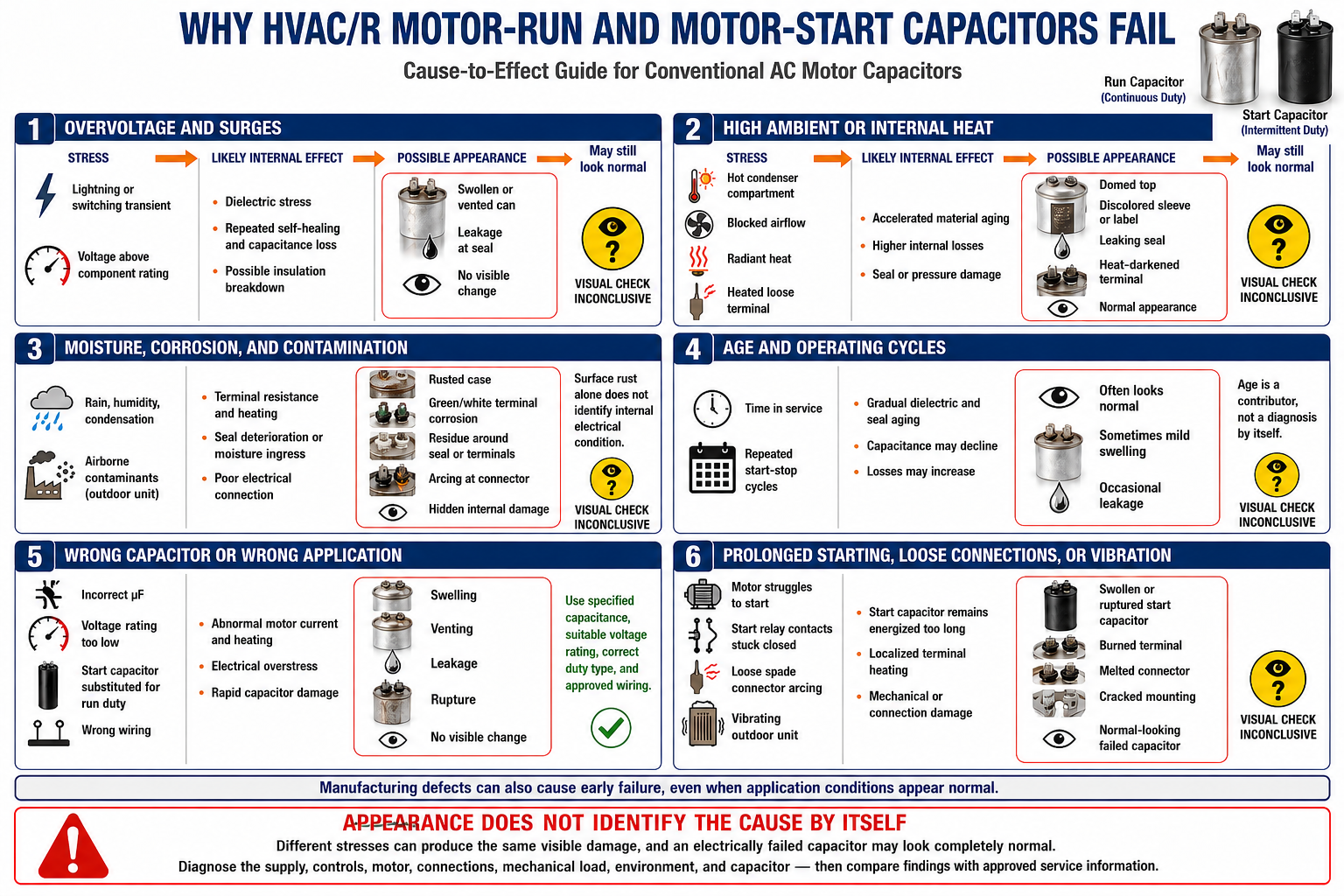
| Failure Influence | How It Affects the Capacitor | What the Technician Should Investigate |
|---|---|---|
| High Ambient Temperature | Heat accelerates dielectric deterioration and increases internal stress. | Check compartment ventilation, nearby heat sources, condenser cleanliness, fan operation, and equipment operating conditions. |
| Voltage Surge or Transient | A brief electrical overvoltage can damage or puncture the dielectric. | Consider storm activity, utility disturbances, switching events, damaged surge protection, and evidence of other electrical damage. |
| Excessive Operating Voltage | Voltage above the capacitor’s application or nameplate limit overstresses the dielectric. | Verify supply voltage, wiring, the required capacitor voltage rating, and actual circuit conditions using approved procedures. |
| Loose or Overheated Connection | Resistance at a poor terminal connection produces heat and can damage the terminal or internal connection. | Inspect push-on connectors, wire terminals, discoloration, looseness, conductor damage, and terminal fit. |
| Incorrect Capacitor | The wrong capacitance, voltage rating, type, duty, or start-assist combination can overload the capacitor or connected equipment. | Compare the installed part with the unit, motor, compressor, and approved replacement specifications. |
| Failed Start Control | A start capacitor left in the circuit too long can overheat rapidly because it is designed for intermittent duty. | Test the potential relay, current relay, PTC device, electronic start control, or other starting device as specified. |
| Moisture and Corrosion | Corrosion can damage terminals, connections, or the case and may allow progressive deterioration. | Look for water entry, condensation, chemical exposure, rust, damaged seals, and cabinet drainage problems. |
| Vibration or Poor Mounting | Movement can fatigue terminals, conductors, internal connections, or the capacitor case. | Check the mounting strap, missing fasteners, compressor or fan vibration, unsupported wiring, and contact with sharp metal. |
| Age | Normal dielectric and seal deterioration can eventually reduce capacitance or cause an open, leaky, or shorted condition. | Confirm the failure by testing and evaluate whether heat or another correctable condition accelerated the aging. |
Visual Damage Is Useful Evidence, but Its Absence Proves Nothing
A visibly swollen, leaking, burned, cracked, or severely corroded capacitor should be removed from service and replaced with the correct component after the surrounding circuit is evaluated. However, a capacitor can lose capacitance, open internally, or develop excessive leakage without any visible change to its case.

| Observed Condition | Possible Meaning | Diagnostic Response |
|---|---|---|
| Bulged or Swollen Case | Internal pressure has operated or distorted the case, often after overheating or dielectric failure. | Replace the capacitor and investigate heat, voltage, application, and connected-load conditions. |
| Oil or Dielectric Leakage | The case or seal has failed. | Replace the capacitor, clean the area using appropriate procedures, and determine why the case failed. |
| Burned or Melted Terminal | A loose connection, poor terminal fit, excessive current, or severe heating may be present. | Replace damaged connectors and conductors as required and diagnose the circuit rather than replacing only the capacitor. |
| Rust or Corrosion | Moisture or chemical exposure may be attacking the case or terminals. | Determine whether the damage affects case integrity or connections and correct the source of moisture or contamination. |
| Cracked or Damaged Case | Mechanical stress, impact, overheating, or environmental damage has compromised the enclosure. | Replace the capacitor and correct mounting, clearance, vibration, or impact problems. |
| Normal Appearance | The capacitor may be good, weak, open, shorted, or electrically unstable despite looking normal. | Perform a safe isolated capacitance test and continue diagnosis of the complete circuit. |
Surface Rust Is Not a Complete Diagnosis
Minor surface rust does not by itself establish the electrical condition of a capacitor, while severe corrosion can compromise terminals, mounting, seals, or the case. Evaluate both the physical condition and the electrical measurement.
Capacitor Problems Can Resemble Other Failures
A weak or open run capacitor may reduce starting torque, disturb motor operation, increase current in a winding, or cause a compressor or fan motor to trip its overload. A failed start capacitor or starting control may cause hard starting, humming, repeated attempts, or an open overload. These symptoms justify testing but do not prove that the capacitor is defective.
Motor Hums but Does Not Start
Possible causes include a failed capacitor, low voltage, a mechanically stuck load, damaged windings, incorrect wiring, or a defective starting device.
Compressor Starts Slowly or Trips
Possible causes include a weak run capacitor, failed start assist, low voltage, high pressure differential, liquid refrigerant, wiring problems, or mechanical compressor damage.
Fan Runs Slowly or Stops
Possible causes include a weak run capacitor, low voltage, bearing drag, a damaged motor winding, a failing motor, or an incorrect replacement motor-capacitor combination.
Repeated Capacitor Failure
Possible causes include high temperature, excessive voltage, loose connections, wrong application, vibration, short cycling, a failed starting control, or a connected component problem.
Isolate Stored Energy Before Measuring Capacitance
Capacitors can retain hazardous electrical energy after the equipment power has been disconnected. OSHA requires stored electrical energy that might endanger personnel to be released, and capacitors must be discharged when their stored energy may create a hazard. Follow the equipment manufacturer’s service instructions, required lockout/tagout practices, and the meter and capacitor manufacturer’s procedures.
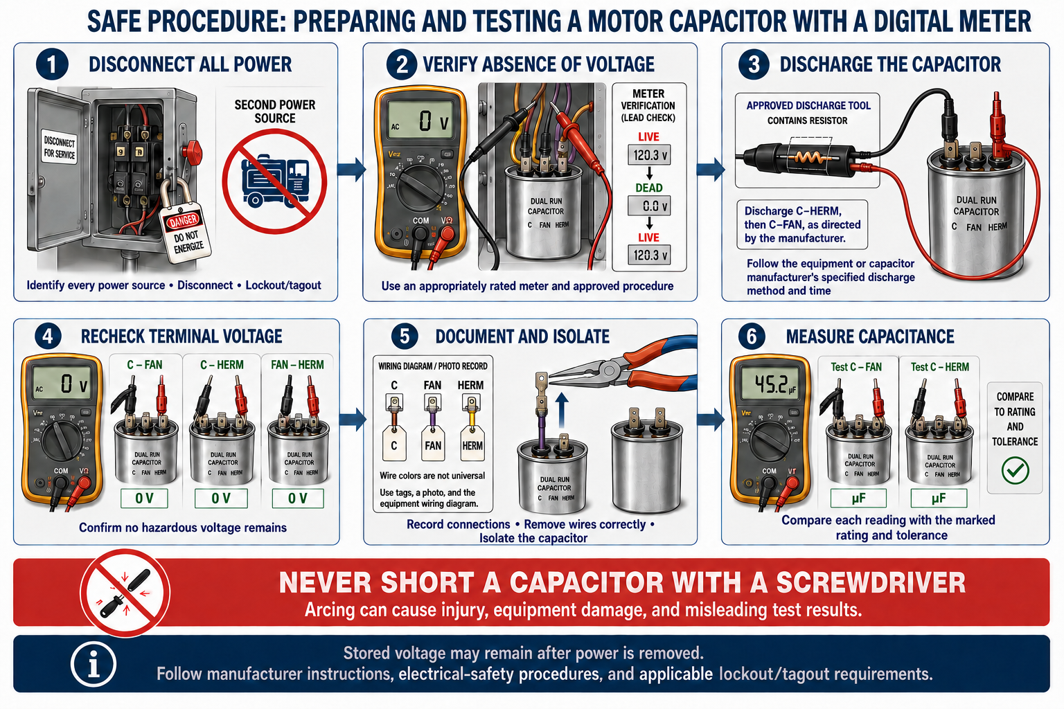
Identify and De-energize
Identify every power source, disconnect the equipment as required, apply lockout/tagout procedures, and follow the manufacturer’s service instructions.
Verify Absence of Voltage
Use a properly rated meter and an approved test method to verify the meter, test the circuit and capacitor terminals, and reverify the meter.
Discharge Safely
Use the manufacturer-specified resistive discharge method and insulated equipment, allow the required time, and then verify the capacitor voltage again.
Document and Isolate
Record or photograph the wiring, identify every conductor, and disconnect the capacitor sufficiently from the circuit for an isolated measurement.
Measure Capacitance
Select the capacitance function, connect the leads to the correct terminal pair, allow the reading to stabilize, and follow the meter manufacturer’s range and connection instructions.
Compare and Diagnose
Compare the result with the specified nominal value and marked tolerance, then inspect the complete motor, compressor, starting circuit, wiring, voltage, and operating conditions.
Do Not Discharge With a Screwdriver
Directly shorting the terminals with a screwdriver can create an arc, damage the capacitor or tool, leave stored energy, and expose the technician to injury. Use the specified resistive discharge method and confirm the result with a meter.
Use the Correct Terminal Pair
A single run or start capacitor is measured across its two terminal groups after it has been safely discharged and isolated. A dual run capacitor contains two separate capacitance sections, and each section must be measured from the common terminal to its identified load terminal.
| Capacitor | Meter Connection | Value to Compare |
|---|---|---|
| Single Run Capacitor | Across the two isolated terminal groups. | Compare with the marked nominal µF value and tolerance. |
| Start Capacitor | Across the two isolated terminal groups. | Compare with the complete marked capacitance range and approved application specification. |
| Dual Run: Compressor Section | C to HERM. | Compare with the larger marked value in a typical rating such as 45/5 µF. |
| Dual Run: Fan Section | C to FAN. | Compare with the smaller marked value in a typical rating such as 45/5 µF. |
Example: 40 µF ±5%
The marked acceptable range is 38 to 42 µF. A stable isolated measurement of 35.8 µF is below the marked tolerance and the capacitor should be replaced with the correctly specified component.
Example: 45/5 µF ±5%
Measure C to HERM and compare with 45 µF, then measure C to FAN and compare with 5 µF. One section may fail even when the other section remains within tolerance.
The Meter Reading Must Be Evaluated in Context
| Test Result | Interpretation | Next Step |
|---|---|---|
| Within Marked Tolerance | The isolated capacitance agrees with the label at the time of the test. | Continue diagnosing voltage, wiring, controls, motor or compressor condition, mechanical load, and operating symptoms. |
| Below or Above Tolerance | The capacitor does not meet its marked capacitance requirement. | Replace it with the correctly specified capacitor and investigate contributing conditions. |
| Open or No Stable Reading | The capacitor, connection, meter range, or test setup may be open or unsuitable. | Verify the meter and connections; replace the capacitor if the open condition is confirmed. |
| Near-Zero Capacitance or Short Indication | An internal short or severe dielectric failure may be present. | Confirm using the meter manufacturer’s procedure, replace the capacitor, and inspect the circuit for additional damage. |
| Unstable or Inconsistent Reading | Poor connections, incomplete isolation, residual charge, meter limitations, or internal capacitor deterioration may be involved. | Stop, make the circuit safe, verify the setup and meter, repeat the approved procedure, and replace the capacitor if it cannot be reliably verified. |
A Capacitance Test Does Not Reproduce Every Operating Stress
A handheld meter applies a small test signal and confirms capacitance under test conditions. It does not by itself prove that insulation, terminals, or internal connections will remain stable at operating voltage and temperature. Physical damage or manufacturer-defined rejection criteria still require replacement.
Determine Whether the Capacitor Is the Cause or a Result
After finding a failed capacitor, inspect the rest of the circuit before returning the equipment to service. A damaged capacitor may be the original fault, or it may have failed because another component or operating condition subjected it to abnormal heat, voltage, current, vibration, or duty.
Electrical Supply
Check supply voltage, voltage drop, connections, contactor condition, conductor damage, and other electrical abnormalities using approved live-testing procedures.
Motor or Compressor
Check winding condition, current, overload status, mechanical freedom where applicable, operating pressure conditions, and manufacturer diagnostic information.
Starting Components
Verify that the relay, PTC, electronic device, or other control inserts and removes starting capacitance as designed.
Operating Environment
Check cooling airflow, compartment heat, water entry, corrosion, vibration, mounting, short cycling, and evidence of repeated electrical disturbances.
Check Your Understanding
1. Why does high ambient temperature shorten capacitor life?
Heat accelerates deterioration of the dielectric, seals, and internal connections and increases the capacitor’s thermal stress.
2. What should be investigated when a start capacitor overheats or fails repeatedly?
Check the start capacitor specification and duty, the starting control, circuit timing, supply voltage, wiring, compressor condition, and the approved start-assist application.
3. Does a normal-looking capacitor have to be electrically good?
No. A capacitor may be weak, open, shorted, or unstable without visible case damage.
4. Does a humming motor prove that its capacitor has failed?
No. A failed capacitor is one possibility, but low voltage, mechanical binding, winding damage, wiring faults, or starting-control problems can produce similar symptoms.
5. Why must a capacitor be isolated before a standard capacitance measurement?
Other circuit paths can affect the reading, so the capacitor must be sufficiently disconnected to obtain a valid isolated measurement.
6. What terminal pairs are used to test a dual run capacitor?
Measure C to HERM for the compressor section and C to FAN for the fan section.
7. Why should a screwdriver not be used to discharge a capacitor?
Direct shorting can create an arc, damage the tool or capacitor, leave stored energy, and expose the technician to injury.
8. What does an isolated reading within tolerance establish?
It establishes that the measured capacitance agrees with the label under the test conditions; it does not prove that every other part of the circuit is good.
9. What should be done after replacing a capacitor with a burned terminal?
Repair or replace damaged connectors and conductors as required, verify terminal fit, and investigate current, heat, wiring, and connected-load conditions.
10. Why should the root cause be investigated after a capacitor failure?
An unresolved problem such as high heat, excessive voltage, a loose connection, incorrect application, vibration, or a failed starting control can damage the replacement.
Key Points to Remember
- Heat, electrical stress, incorrect application, loose connections, corrosion, vibration, starting-control faults, and age can contribute to capacitor failure.
- Bulging, leakage, burned terminals, severe corrosion, and case damage are rejection clues, but many failed capacitors look normal.
- A motor or compressor symptom does not by itself prove that a capacitor has failed.
- Control every power source, follow lockout/tagout requirements, verify absence of voltage, discharge stored energy safely, and verify again before handling a capacitor.
- Do not discharge capacitor terminals with a screwdriver.
- Isolate the capacitor before making a standard capacitance measurement.
- Measure a dual run capacitor from C to HERM and from C to FAN.
- Compare the reading with the specified nominal value and the capacitor’s marked tolerance or range.
- A normal capacitance reading does not eliminate wiring, control, motor, compressor, mechanical, or operating-condition faults.
- Find and correct the reason for a failure before placing the equipment back into service.