DC Bus Capacitors in Inverter-Driven HVAC/R Equipment
Variable-frequency drives and inverter-driven HVAC/R equipment use a power-electronics section to convert incoming AC power into controlled output for a compressor, fan, pump, or other motor. High-voltage DC bus capacitors are central to that conversion process.
These capacitors are different from conventional motor run and start capacitors. They operate inside an electronic drive, may store hazardous energy long after incoming power is disconnected, and normally require equipment-specific training, test points, procedures, and replacement parts.
Learning Objectives
Trace Power Conversion
Follow electrical power from the AC input through the rectifier, DC bus, inverter switching section, and variable-speed motor.
Explain the DC Bus Capacitor
Describe how DC bus capacitors smooth rectified voltage, reduce ripple, and provide short-term energy storage for the inverter.
Recognize Stored-Energy Hazards
Explain why hazardous DC voltage can remain after the disconnect is opened and why indicator lights and elapsed time alone are not proof of a safe condition.
Identify Failure Clues
Relate heat, ripple current, age, voltage stress, cooling problems, and electrical faults to DC bus capacitor deterioration and drive symptoms.
DC Bus Capacitors Are Part of the Electronic Drive
A conventional run capacitor is connected to a single-phase motor winding to create the phase relationship needed for motor operation. A start capacitor provides brief starting torque and is then removed from the circuit. A DC bus capacitor performs neither of those jobs. It is located between the input rectifier and the inverter switching section of an electronic drive.
| Capacitor Application | Electrical Location | Main Function | Typical Service Approach |
|---|---|---|---|
| Run Capacitor | In a conventional single-phase motor circuit. | Maintains the designed current and phase relationship between motor windings. | May be tested as an isolated component using its marked capacitance and tolerance. |
| Start Capacitor | In a starting circuit controlled by a relay, PTC device, electronic control, or other approved device. | Provides additional phase shift and starting torque for a brief interval. | Test the capacitor and the device that inserts and removes it from the circuit. |
| DC Bus Capacitor | Across the high-voltage DC link inside a drive or inverter assembly. | Smooths rectified DC, reduces ripple, and stores energy used by the inverter switching section. | Follow the exact equipment service procedure; board or drive assembly replacement may be required. |
The DC Bus Connects the Rectifier and Inverter
In a common drive arrangement, incoming AC power first passes through protection, filtering, and sometimes a power-factor-correction or soft-charge circuit. A rectifier converts the AC input into pulsating DC. The DC bus capacitors smooth that pulsating voltage and provide an energy reservoir. Semiconductor switches in the inverter then pulse the DC bus voltage to create controlled output for the motor.
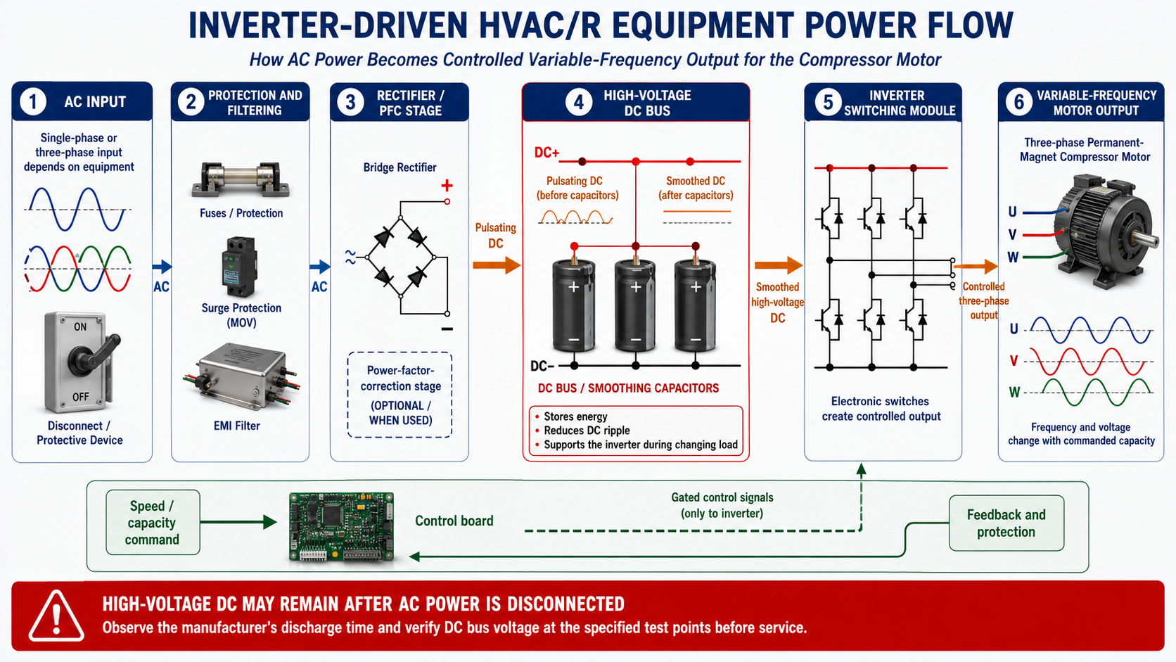
AC Input
Single-phase or three-phase AC enters the drive through the equipment’s protective and conditioning components.
Rectification
Diodes or controlled semiconductor devices convert the incoming AC waveform into pulsating DC.
DC Bus
Capacitors reduce voltage ripple and store energy between the rectifier and inverter sections.
Inverter Switching
Power transistors switch the DC bus voltage rapidly to create a controlled output waveform.
Variable-Speed Motor
The controlled output changes motor speed and torque to match compressor, fan, or pump demand.
The DC Bus Voltage Can Exceed the AC Input Number
Rectification and capacitor charging produce a DC voltage related to the peak of the AC waveform, not merely its RMS nameplate value. A nominal 240-volt AC input can produce approximately 340 volts DC in a basic full-wave rectifier arrangement, and power-factor-correction circuits or other designs may operate at different or higher DC bus voltages.
The Rectifier Alone Does Not Produce Smooth DC
The output of a basic rectifier rises and falls with the peaks of the incoming AC waveform. DC bus capacitors charge when rectifier voltage is high and release energy as rectifier voltage falls. This action reduces ripple and helps maintain a usable DC supply for the inverter between waveform peaks.
Voltage Smoothing
The capacitor reduces the rise and fall of the rectified DC voltage presented to the inverter.
Energy Storage
The capacitor supplies short bursts of energy as the inverter and motor load change.
Rectifier–Inverter Link
The DC bus separates the input conversion process from the controlled output switching process.
Ripple Control
A healthy capacitor bank helps limit DC bus ripple within the drive’s designed operating range.
Opening the Disconnect Does Not Immediately Make the DC Bus Safe
DC bus capacitors can remain charged after incoming power is removed. Many drives include discharge or bleed resistors, but discharge time varies with the design and a failed discharge path can leave hazardous voltage on the bus. Some systems may also have alternate energy sources, shared DC links, battery or UPS connections, or a permanent-magnet motor capable of generating voltage while rotating.
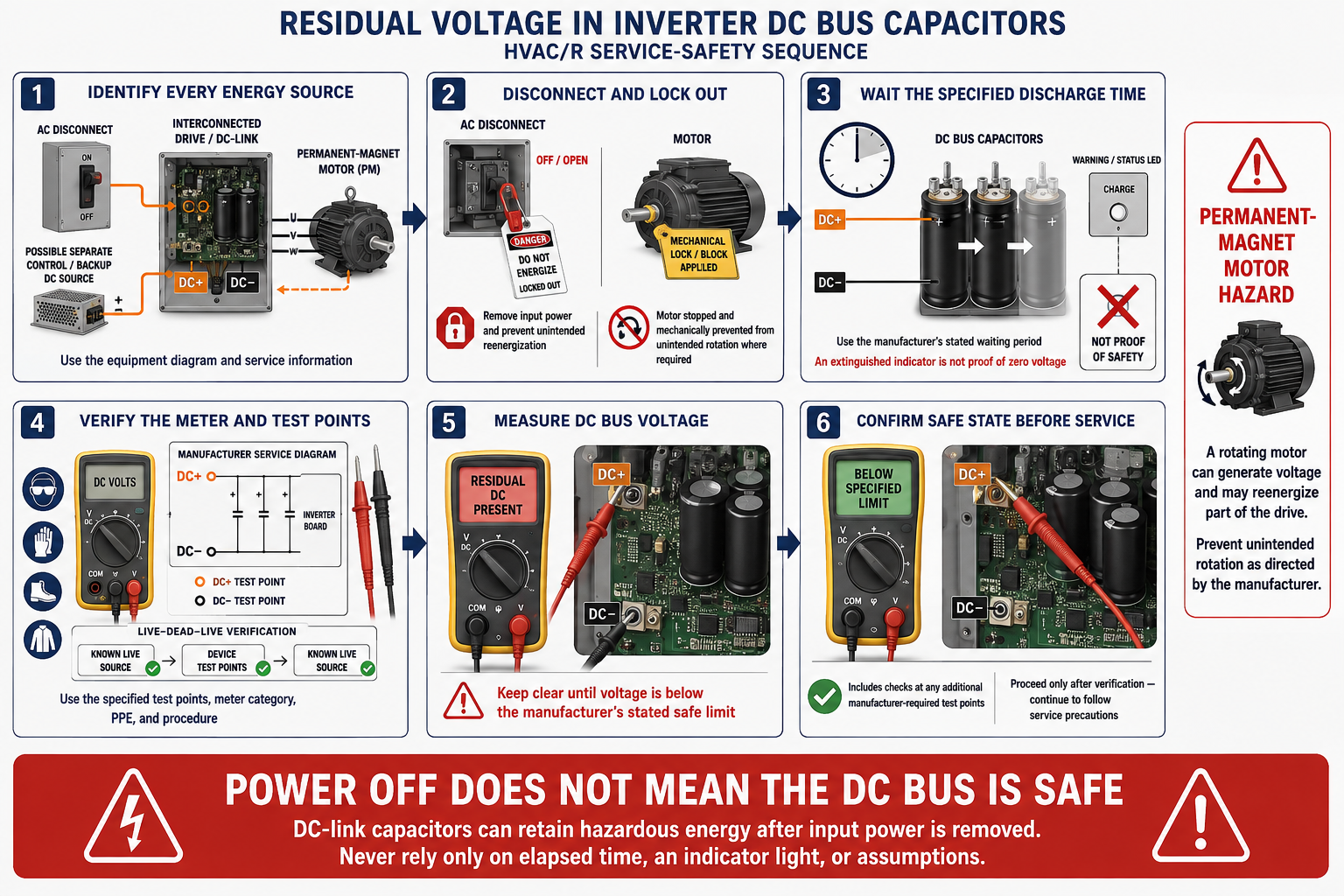
Obtain the Correct Procedure
Identify the exact equipment model and use its current installation, service, and electrical-safety documentation.
Identify Every Energy Source
Account for AC input, remote disconnects, backup supplies, shared DC links, control power, and possible permanent-magnet motor generation.
Disconnect and Lock Out
Stop the equipment and apply the required disconnecting, lockout/tagout, and stored-energy-control procedures.
Wait the Specified Time
Observe the complete manufacturer-specified discharge interval for that model and voltage class.
Verify at Designated Points
Qualified personnel must use the specified meter, personal protective equipment, test points, and live-dead-live verification method.
Begin Work Only When Authorized
Proceed only when the equipment-specific procedure confirms that the circuit is in the required safe condition.
No Universal Waiting Time Makes Every Inverter Safe
Required waiting times differ by manufacturer, model, drive size, and circuit design. Waiting five minutes, fifteen minutes, or any other assumed interval is not a substitute for the equipment instructions and an actual voltage measurement at the designated points.
Do Not Improvise a Discharge Method
Do not short the DC bus with a screwdriver, jumper, meter lead, or improvised resistor. The available energy can produce a destructive arc, component damage, fire, or serious injury. Follow only the manufacturer’s documented discharge and verification procedure.
DC Bus Capacitors Operate Under High Electrical and Thermal Stress
Many HVAC/R inverter boards use polarized aluminum electrolytic capacitors because they can provide substantial capacitance in a compact package, although designs may also use film capacitors or combinations of capacitor types. Electrolytic capacitors commonly have polarity markings and pressure-relief features and must be installed only in the orientation and circuit for which they were designed.

| Stress or Failure | Effect on the Capacitor or Drive | Possible Evidence |
|---|---|---|
| High Temperature | Accelerates electrolyte loss and deterioration of seals and internal materials. | Heat-discolored board areas, failed cooling fans, blocked airflow, dirty heat sinks, or repeated overtemperature faults. |
| Ripple Current Stress | Produces internal heating as the capacitor repeatedly charges and discharges. | Elevated bus ripple, heating, progressive capacitance loss, or drive instability. |
| Overvoltage or Transient | Overstresses the dielectric and can cause leakage, breakdown, venting, or a short circuit. | DC overvoltage alarms, surge evidence, damaged rectifier or inverter components, or a ruptured capacitor. |
| Increased ESR | Higher equivalent series resistance increases internal heating and reduces the capacitor’s ability to handle ripple current. | Excessive ripple, heating, intermittent operation, or failure that may not be visible. |
| Reduced Capacitance | The bus stores less energy and its voltage may fluctuate more under load. | Undervoltage faults, unstable operation, increased ripple, or difficulty supporting rapid load changes. |
| Open Connection | One capacitor or part of a capacitor bank no longer contributes to the DC link. | High ripple, low effective capacitance, damaged solder joints, or intermittent faults. |
| Short Circuit | Can draw destructive current through the rectifier, precharge circuit, fuse, trace, or capacitor. | Blown protection devices, burned components, severe board damage, or immediate drive failure. |
A DC Bus Fault Code Does Not Automatically Identify the Capacitor
Drive alarms and operating symptoms must be interpreted using the manufacturer’s diagnostic sequence. A DC bus undervoltage fault can result from low supply voltage, an open input phase, a rectifier problem, a failed precharge circuit, loose wiring, excessive load, or deteriorated capacitors. A DC overvoltage fault can involve supply conditions, regenerative energy, deceleration settings, load behavior, braking components, or control problems rather than a failed capacitor.
Undervoltage or Bus-Low Fault
Verify incoming power, connections, rectification, precharge operation, loading, and the manufacturer’s specified DC bus checks before condemning the capacitors.
Overvoltage or Bus-High Fault
Evaluate supply voltage, regenerative conditions, rapid deceleration, motor behavior, and the specified braking or control circuits.
Excessive Ripple or Unstable Operation
Possible causes include capacitor deterioration, an input phase or rectifier problem, poor connections, excessive load, or a measurement setup that does not match the service procedure.
Blown Fuse or Damaged Board
A shorted capacitor is possible, but rectifier, inverter transistor, surge-protection, wiring, and other board faults must also be evaluated.
Do Not Probe an Operating Inverter Without the Required Qualification
Live DC bus and inverter measurements can expose the technician and test equipment to high voltage, high available energy, fast switching waveforms, and destructive transients. Use only the manufacturer-specified instruments, ratings, probes, personal protective equipment, test points, and procedures.
Follow the Manufacturer’s Repair Level
Some manufacturers authorize only complete inverter-board, power-module, or drive replacement in the field. Others provide specific component-level procedures for trained service personnel. Replacing a DC bus capacitor solely by matching microfarads and voltage is not sufficient because ripple-current rating, ESR, temperature class, life rating, polarity, physical dimensions, terminal arrangement, mounting, safety approvals, and capacitor-bank design also matter.
| Service Question | Required Verification |
|---|---|
| Is Component-Level Repair Authorized? | Use the equipment manufacturer’s service policy and documentation. Do not assume that a soldered capacitor is an approved field-replaceable part. |
| What Is the Correct Replacement? | Use the exact approved part or a replacement documented as electrically, thermally, mechanically, and environmentally suitable. |
| Is the Capacitor Bank Series-Connected? | Verify the complete bank design, voltage-sharing components, polarity, and manufacturer replacement instructions. |
| Why Did It Fail? | Inspect cooling, fans, heat sinks, supply conditions, rectifier, precharge circuit, inverter devices, loading, contamination, and related fault history. |
| How Is the Repair Verified? | Follow the prescribed inspections, insulation checks, power-up sequence, fault-code review, and operating tests before returning the equipment to service. |
Avoid Applying Conventional Capacitor Assumptions
“The Disconnect Is Open, So the Board Is Safe”
The DC bus may retain hazardous energy after input power is removed, and alternate sources or a rotating permanent-magnet motor may energize parts of the drive.
“The Indicator Light Is Off, So Voltage Is Gone”
An extinguished display or charge indicator is not a substitute for the required waiting time and an approved voltage measurement.
“All Drives Discharge in Five Minutes”
Discharge times vary. Use the exact value and verification method specified for the equipment being serviced.
“A Bus Fault Means Bad Capacitors”
Supply, rectifier, precharge, inverter, braking, motor, load, wiring, and control problems can produce similar faults.
“Matching µF and Voltage Is Enough”
Ripple-current capability, ESR, temperature, life, polarity, dimensions, terminals, bank arrangement, and manufacturer approval also matter.
“A Normal-Looking Capacitor Is Good”
Capacitance loss and increased ESR can occur without swelling, leakage, or other visible damage.
Review Questions
1. Where is the DC bus located in a common inverter power path?
Answer: It is located between the input rectifier and the inverter switching section.
2. What are the main functions of DC bus capacitors?
Answer: They smooth rectified DC voltage, reduce ripple, and store energy used by the inverter.
3. Why can DC bus voltage be higher than the AC input’s RMS number?
Answer: The rectifier and capacitors charge toward the peak of the AC waveform, and some equipment also uses power-factor-correction or other voltage-boosting circuitry.
4. Does opening the equipment disconnect immediately make the DC bus safe?
Answer: No. The capacitors can retain hazardous energy, and other sources may also energize the drive.
5. Why is an extinguished charge light not proof of zero voltage?
Answer: The indicator or its circuit may not show every hazardous condition, so the specified waiting time and approved voltage verification are still required.
6. Should a technician use a standard assumed waiting time for every drive?
Answer: No. The technician must use the discharge time and verification procedure specified for the exact equipment.
7. What is ESR, and why does an increase matter?
Answer: ESR is equivalent series resistance. Increased ESR creates more internal heating under ripple current and reduces effective capacitor performance.
8. Does a DC bus undervoltage fault prove that the bus capacitors are defective?
Answer: No. Low supply voltage, wiring, rectifier, precharge, input-phase, loading, and other problems can cause a similar fault.
9. Why is matching capacitance and voltage alone insufficient for replacement?
Answer: Ripple current, ESR, temperature, life, polarity, dimensions, terminals, mounting, bank design, approvals, and manufacturer authorization must also be satisfied.
10. When should an individual DC bus capacitor be replaced in the field?
Answer: Only when the manufacturer authorizes that repair level and qualified personnel can follow the specified safety, component-selection, installation, and verification procedures.
Lesson 6 Summary
- DC bus capacitors are part of an electronic drive and do not perform the same function as conventional motor run or start capacitors.
- The rectifier converts AC input to pulsating DC, the DC bus capacitors smooth and store energy, and the inverter switches that energy into controlled motor output.
- A nominal 240-volt AC source can produce approximately 340 volts DC in a basic rectifier-capacitor circuit, and some drive designs operate at other or higher bus voltages.
- DC bus capacitors can retain hazardous energy after incoming power is disconnected.
- Alternate sources, shared DC links, backup power, and rotating permanent-magnet motors may create additional hazards.
- Always use the exact manufacturer-specified discharge time, test points, meter, protective equipment, and verification procedure.
- Never rely only on elapsed time, a dark display, or an extinguished charge indicator.
- Heat, ripple current, overvoltage, age, increased ESR, capacitance loss, open connections, and shorts can affect the DC bus.
- A DC bus fault code does not automatically prove that the capacitors have failed.
- Field repair may require replacement of the complete board, power module, or drive rather than an individual capacitor.
- An approved replacement must satisfy ripple current, ESR, temperature, life, polarity, mechanical, electrical, and manufacturer requirements.