Capacitor-Start Motors: CSIR and CSCR
Capacitor-start motors place a start capacitor in series with the auxiliary winding during acceleration. The increased capacitance creates strong phase displacement and high starting torque, making these motors suitable for compressors, pumps, and other loads that are more difficult to start than typical fan loads.
Capacitor-start induction-run, or CSIR, motors remove the start capacitor and auxiliary winding after starting. Capacitor-start capacitor-run, or CSCR, motors remove the start capacitor but keep the auxiliary winding energized through a run capacitor. Correct diagnosis requires identifying the exact motor circuit, capacitors, relay or switch, overload, and mechanical or refrigerant load.
Learning Objectives
Explain Capacitor Starting
Describe how a start capacitor and auxiliary winding create the phase displacement required for high starting torque.
Distinguish CSIR and CSCR
Identify which windings and capacitors are energized during the starting and running conditions of each design.
Explain Start-Relay Operation
Compare the basic actions of current relays, potential relays, centrifugal switches, and approved electronic starting devices.
Diagnose Starting Circuits
Evaluate the supply, overload, windings, capacitors, relay or switch, connections, motor load, and equipment operating conditions.
High Starting Torque Requires Strong Phase Displacement
A resistance-start split-phase motor creates moderate phase displacement through different main- and auxiliary-winding characteristics. Adding a correctly selected start capacitor in series with the auxiliary winding increases the current displacement and strengthens the rotating magnetic effect during starting.
The resulting torque helps accelerate loads with higher breakaway torque, inertia, or pressure difference. Once the motor reaches the required speed, the high-capacitance start circuit must be removed because the start capacitor and, in a CSIR motor, the auxiliary winding are designed for short-duration starting duty.
Capacitor Start, Induction Run
A CSIR motor uses a main winding, an auxiliary winding, a start capacitor, and a starting device. During starting, the main winding is connected across the supply and the start capacitor is connected in series with the auxiliary winding. Both winding fields contribute to high starting torque.
After the motor accelerates, the starting device opens the auxiliary circuit. The start capacitor and auxiliary winding are disconnected, and the motor continues operating as an induction motor on the main winding alone. There is no run capacitor in a basic CSIR circuit.
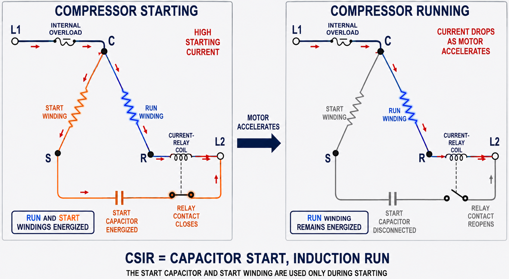
The Compressor Is Energized
Supply voltage is applied through the control and overload circuit to the compressor terminals.
High Starting Current Operates the Relay
In the illustrated current-relay circuit, high run-winding current energizes the relay coil strongly enough to close the normally open start contact.
Both Windings Produce Torque
The main winding and the start-capacitor-and-auxiliary branch create the displaced magnetic effects needed for acceleration.
Current Falls as Speed Rises
As the rotor accelerates, main-winding current falls from its starting value and the current relay begins to release.
The Start Contact Opens
The relay contact reopens and disconnects the start capacitor and auxiliary winding from the circuit.
The Motor Runs on the Main Winding
The rotor continues turning below synchronous speed and develops running torque through induction.
A Current Relay Must Match the Compressor
The relay must close at sufficient starting current and reopen after acceleration. An incorrect relay may fail to energize the start circuit, keep it energized too long, chatter, or disconnect at the wrong point. Use the compressor and equipment manufacturer’s specified part or approved replacement.
Capacitor Start, Capacitor Run
A CSCR motor uses both a start capacitor and a run capacitor. During starting, the effective capacitance in the auxiliary circuit is increased—commonly by connecting the start capacitor so it operates with the run capacitor—to produce high starting torque. The exact circuit must be determined from the equipment diagram.
After acceleration, the start relay opens and removes only the start capacitor. The run capacitor remains in series with the auxiliary winding, so both motor windings continue operating. This provides running characteristics that differ from a CSIR motor, including the potential for improved efficiency, power factor, torque, and temperature performance when properly designed.
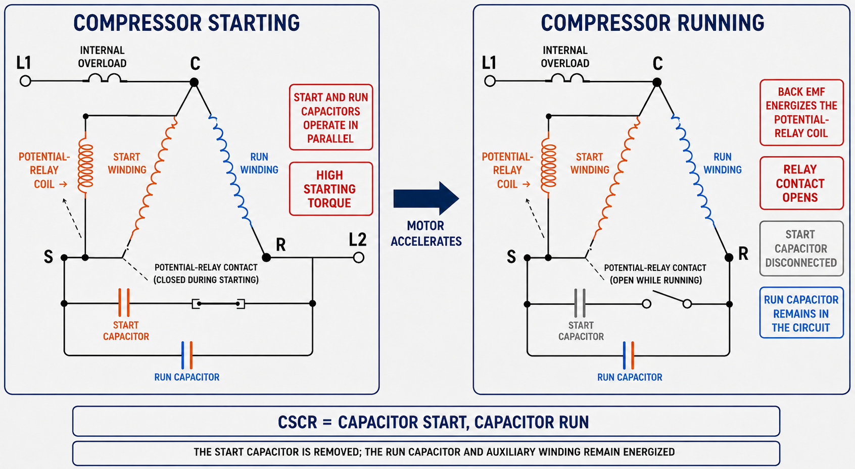
Start Contact Is Closed
The normally closed potential-relay contact connects the start capacitor into the auxiliary circuit while the motor is stopped.
High Starting Torque Develops
Start and run capacitance create the phase relationship needed to accelerate the compressor load.
Back EMF Rises
As the motor accelerates, voltage associated with the auxiliary winding rises and energizes the potential-relay coil.
The Start Capacitor Disconnects
At the relay pickup point, the normally closed contact opens and removes the short-duty start capacitor.
Run Capacitance Remains
The auxiliary winding continues operating through the continuously rated run capacitor.
The Relay Resets After Stopping
As the motor stops and winding voltage falls, the relay drops out and its contact closes for the next start.
Follow the Components Through Starting and Running
| Characteristic | CSIR | CSCR |
|---|---|---|
| Full Name | Capacitor-start induction-run | Capacitor-start capacitor-run |
| Start Capacitor | Energized only during starting. | Energized only during starting. |
| Run Capacitor | Not used in the basic design. | Remains energized during starting and running. |
| Auxiliary or Start Winding | Energized during starting and then disconnected. | Energized during starting and remains energized through the run capacitor. |
| Main or Run Winding | Energized during starting and running. | Energized during starting and running. |
| Running Condition | Runs on the main winding alone. | Runs on the main winding plus the run-capacitor-and-auxiliary branch. |
| Starting Torque | High when correctly applied. | High when correctly applied. |
| Common Starting Device | Current relay, centrifugal switch, or another approved device depending on the motor. | Potential relay, centrifugal switch, or another approved device depending on the motor. |
Different Duties Require Different Components
| Characteristic | Start Capacitor | Run Capacitor |
|---|---|---|
| Primary Purpose | Provide increased starting phase displacement and torque. | Maintain the designed auxiliary-current relationship during continuous operation. |
| Duty | Short-duration, intermittent starting duty. | Continuous AC motor-running duty. |
| Typical Capacitance | Relatively high for the motor application. | Lower than the associated start capacitance in a typical CSCR circuit. |
| Time in Circuit | Only during acceleration. | During starting and running in a CSCR motor. |
| Failure if Misapplied | Can overheat, vent, rupture, or damage the winding if left energized. | Incorrect capacitance can cause poor torque, high current, heat, noise, and reduced motor life. |
Match Microfarads
Use the capacitance and tolerance specified for the motor and the identified start or run function. Do not select a value by physical size.
Match Voltage Rating
Use the specified minimum capacitor VAC rating. Circuit voltage across a capacitor is not assumed to equal the line voltage.
Use the Correct Duty Type
A continuously rated run capacitor and a short-duty start capacitor are not interchangeable even when another marking appears similar.
Inspect Connections and Mounting
Loose terminals, heat, vibration, corrosion, incorrect mounting, and contact with sharp or hot surfaces can cause repeated failures.
Stored Energy and Failure Hazards
Capacitors can retain hazardous voltage after power is removed and may fail violently if misapplied. Follow the required energy-control procedure and the manufacturer’s approved discharge and verification method before handling terminals or testing an isolated capacitor.
The Motor Determines How the Start Circuit Is Removed
Current Relay
A current relay responds to high starting current, commonly through a coil in series with the run winding. Its normally open contact closes the start circuit and reopens as current falls.
Potential Relay
A potential relay responds to voltage associated with the auxiliary winding. Its normally closed contact opens when rising back EMF reaches the pickup level and recloses after voltage falls to dropout.
Centrifugal Switch
A shaft-mounted mechanism responds directly to motor speed and opens stationary contacts after acceleration. It is common in accessible motors rather than inside a welded hermetic compressor shell.
Electronic Start Device
An approved solid-state or timed device may control a start circuit, but its ratings, timing, reset behavior, motor compatibility, and equipment approval must match the application.
Do Not Select a Relay by Contact Appearance
Pickup, dropout, current, voltage, contact, timing, mounting, and terminal arrangements matter. An incorrect relay can prevent starting or leave the start capacitor energized. Use manufacturer-authorized selection information.
High-Torque Designs Serve Harder-to-Start Loads
Hermetic Compressors
Single-phase reciprocating, rotary, and scroll compressor applications may use CSIR, CSCR, PSC with approved start assist, or another design selected by the manufacturer.
Pumps
Some pumps require increased breakaway torque because of hydraulic load, seals, impeller condition, or the need to restart under system pressure.
Compressors and Air Equipment
Some non-hermetic compressors and other high-inertia or high-breakaway-torque loads use capacitor-start motors with centrifugal switches or relays.
Special Equipment Loads
Conveyors, tools, and machinery may use these designs when the motor torque curve, duty, speed, environment, and controls match the load.
The Motor Must Accelerate Before Protection Opens
Starting components cannot compensate indefinitely for an abnormal electrical or mechanical condition. Low supply voltage, excessive voltage drop, short cycling, high pressure difference, refrigerant migration, a tight mechanism, incorrect components, overheated windings, or a damaged compressor can extend starting time or prevent acceleration.
The compressor’s overload may open when current or internal temperature exceeds its response. If it automatically resets, the compressor may attempt another start while still hot or while system pressures remain unfavorable. Repeated cycling is not a repair and can damage the motor, relay, capacitor, contactor, and terminals.
Voltage Under Starting Load
Measure with a properly rated instrument and approved energized-work procedure. Static voltage with the motor off does not reveal starting voltage drop.
Pressure Equalization
Some systems require off-cycle time for pressure conditions to equalize. Controls must prevent damaging rapid restart where the equipment design requires a delay.
Contactor and Connections
Pitted contacts, loose terminals, damaged conductors, and poor connections can create voltage drop, heat, and unreliable starting.
Correct Refrigerant Operation
Restrictions, loss of cooling, abnormal pressures, inadequate charge, or operation outside the compressor envelope can overload or overheat the compressor.
Determine Whether the Start Circuit Enters and Leaves Correctly
| Symptom | Possible Starting-Circuit Causes | Other Possible Causes |
|---|---|---|
| Hums or Draws Locked-Rotor Current | Open start capacitor, relay fails to close, open auxiliary winding, incorrect wiring, or failed connection. | Low voltage, bound compressor or pump, excessive pressure difference, open run winding, or internal motor damage. |
| Starts Slowly | Weak or incorrect start capacitor, wrong relay, poor contacts, incorrect run capacitor in CSCR, or intermittent start circuit. | Voltage drop, high load, bearing or mechanism drag, wrong motor, or winding damage. |
| Start Capacitor Overheats or Fails | Relay contact fails to open, wrong capacitor, repeated starts, relay chatter, or miswiring. | Motor never reaches relay transfer conditions because of low voltage or excessive load. |
| High Running Current | Start circuit remains energized, incorrect run capacitor, wrong wiring, or incorrect relay application. | Overload, voltage problem, winding damage, abnormal pressure, inadequate cooling, or unsuitable motor. |
| Overload Cycles | Failed starting components, prolonged acceleration, start circuit remains connected, or incorrect components. | Mechanical overload, low voltage, high ambient, short cycling, refrigerant-system problem, or internal compressor fault. |
| Relay Chatters | Incorrect relay, marginal pickup or dropout conditions, loose connection, or unstable coil voltage or current. | Fluctuating supply, failure to accelerate, rapidly changing load, or control-circuit problems. |
Identify the Circuit Before Taking Measurements
Identify CSIR or CSCR
Use the compressor or motor model, equipment schematic, parts data, capacitor labels, relay information, and terminal markings to identify the actual circuit.
Inspect Before Starting
Look for swollen or leaking capacitors, overheated terminals, damaged wiring, loose connections, pitted contactor contacts, incorrect components, and signs of repeated overload operation.
Evaluate Starting Operation
When safe for a qualified person, measure supply voltage and current during starting and determine whether the start circuit engages, the motor accelerates, and the start capacitor disconnects.
Control Hazardous Energy
Isolate all energy sources, apply the required energy-control procedure, verify de-energization, and discharge and verify capacitors using an approved method.
Test Isolated Components
Following manufacturer procedures, test capacitors, relay coil and contacts, winding resistance and insulation, overload continuity when applicable, conductors, and terminal connections.
Find the Cause and Verify
Correct the supply, control, load, refrigerant, or mechanical condition that caused the failure and confirm reliable starts, correct transfer, normal current, and acceptable operation.
Do Not Bypass the Overload or Hold the Start Circuit Closed
Bypassing protection or manually maintaining start capacitance can overheat windings, rupture a capacitor, damage terminals, and create shock, arc, or fire hazards. Use only approved diagnostic procedures and correctly rated replacement components.
Avoid These Errors
“CSIR Uses a Run Capacitor”
A basic CSIR motor disconnects the start capacitor and auxiliary winding and runs on the main winding alone.
“CSCR Leaves Both Capacitors Connected”
The start capacitor is removed after acceleration. Only the run capacitor remains in the auxiliary circuit.
“Start and Run Capacitors Are Interchangeable”
They have different capacitance ranges, construction, and duty. Use the exact type and ratings specified for each function.
“Every Compressor Uses a Potential Relay”
Starting devices vary. The actual circuit may use a current relay, potential relay, electronic device, or another approved arrangement.
“A New Start Kit Fixes Every Hard Start”
A start kit cannot correct low voltage, a damaged compressor, incorrect wiring, abnormal pressures, short cycling, failed contacts, or an application problem.
“An Overload Reset Means the Compressor Is Good”
Reset only permits another attempt. The condition that caused excessive current or temperature must be identified before continued operation.
Review Questions
1. What does CSIR stand for?
Answer: Capacitor-start induction-run.
2. Which motor circuits remain energized after a CSIR motor accelerates?
Answer: The main or run winding remains energized; the start capacitor and auxiliary winding are disconnected.
3. What does CSCR stand for?
Answer: Capacitor-start capacitor-run.
4. Which components remain energized after a CSCR motor accelerates?
Answer: The main winding remains energized, and the auxiliary winding continues operating through the run capacitor; the start capacitor is disconnected.
5. How does the current relay in the illustrated CSIR circuit respond during starting?
Answer: High starting current energizes its coil and closes the start contact; as current falls after acceleration, the contact reopens.
6. What causes the potential relay in the illustrated CSCR circuit to open its contact?
Answer: Rising back EMF associated with motor acceleration energizes the relay coil to its pickup point and opens the normally closed contact.
7. Why must a start capacitor be removed after acceleration?
Answer: It is a short-duty component; prolonged energization can cause overheating, failure, and winding damage.
8. Name four conditions outside the start components that can prevent a compressor motor from accelerating.
Answer: Examples include low voltage, excessive voltage drop, abnormal pressure difference, short cycling, a tight mechanism, winding damage, poor connections, or operation outside the compressor’s approved conditions.
Lesson 8 Summary
- Capacitor-start motors use a start capacitor and auxiliary winding to produce high starting torque.
- The start capacitor is designed for short-duration duty and must disconnect after acceleration.
- CSIR means capacitor-start induction-run.
- A CSIR motor disconnects the start capacitor and auxiliary winding and runs on the main winding alone.
- CSCR means capacitor-start capacitor-run.
- A CSCR motor disconnects the start capacitor but keeps the auxiliary winding energized through the run capacitor.
- A current relay commonly responds to high starting current and releases as motor current falls.
- A potential relay commonly responds to rising auxiliary-winding back EMF and opens its normally closed start contact.
- Centrifugal and electronic starting devices may be used in other approved motor circuits.
- Start and run capacitors have different capacitance, construction, and duty requirements and are not interchangeable.
- Capacitance, tolerance, voltage rating, relay characteristics, and wiring must match manufacturer specifications.
- High starting torque makes capacitor-start motors suitable for many compressors, pumps, and other difficult-to-start loads.
- Low voltage, pressure conditions, mechanical load, short cycling, controls, and wiring can cause a start-circuit symptom.
- A start circuit that fails to disconnect can overheat the capacitor and auxiliary winding.
- Troubleshooting must identify the circuit and evaluate the supply, controls, overload, relay, capacitors, windings, connections, and load.