Permanent Split Capacitor Motors
A permanent split capacitor motor uses a run capacitor in series with its auxiliary winding to create phase displacement. The capacitor and auxiliary winding remain in the circuit during both starting and normal operation, so the motor does not require a centrifugal switch to remove a starting circuit.
PSC motors have been widely used for HVAC/R blowers, condenser fans, evaporator fans, and pumps. Understanding the permanent capacitor circuit, multi-speed leads, airflow-dependent cooling, and capacitor requirements is essential for correct testing and replacement.
Learning Objectives
Identify PSC Construction
Recognize the main winding, auxiliary winding, run capacitor, squirrel-cage rotor, shaft, bearings, and absence of a centrifugal switch.
Explain Permanent Capacitance
Describe how the run capacitor creates phase displacement and why it remains connected during starting and running.
Connect Multi-Speed Motors
Identify common, capacitor, and speed leads and explain why only one speed tap may be energized at a time.
Diagnose PSC Problems
Evaluate the supply, capacitor, windings, speed selection, bearings, airflow, mechanical load, rotation, and motor application.
The Run Capacitor Is a Permanent Part of the Circuit
A PSC motor has a main winding connected across the supply and an auxiliary winding connected in series with a run capacitor. The winding magnetic axes are displaced in the stator, and the capacitor changes the timing of current in the auxiliary circuit. The two magnetic effects combine to establish starting direction and improve running operation.
The same run capacitor is used during starting and running. There is no centrifugal switch in the basic PSC design because no start-only winding or start capacitor must be removed after acceleration. The motor continues operating with both stator windings energized.
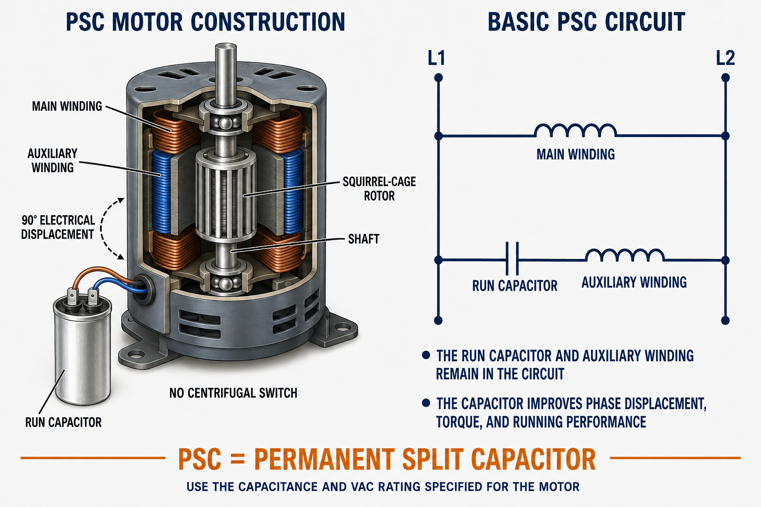
| Component | Function | Service Significance |
|---|---|---|
| Main Winding | Produces the primary motor field during starting and running. | Some blower motors use taps in the main winding to provide multiple operating speeds. |
| Auxiliary Winding | Produces a displaced magnetic field through its series run capacitor. | It remains energized while the motor operates and is not a short-duty start-only winding. |
| Run Capacitor | Changes auxiliary-circuit current timing and supports starting and running performance. | The required capacitance, tolerance, type, and voltage rating must match the motor specification. |
| Squirrel-Cage Rotor | Develops torque through induced rotor current and magnetic-field interaction. | Rotor damage, rubbing, bearing wear, or mechanical overload affects current, speed, heat, and torque. |
| Shaft and Bearings | Support rotation and transfer torque to the blower, fan, pump, or other load. | Drag or misalignment can prevent starting or cause high current and overheating. |
| Thermal Protection | Interrupts operation under specified abnormal temperature or current conditions when provided. | Repeated cycling indicates an unresolved electrical, mechanical, airflow, ambient, or application problem. |
Capacitance Creates the Required Phase Displacement
Without the auxiliary branch, a single main winding would not establish a definite starting direction at standstill. The run capacitor changes the phase relationship of current in the auxiliary winding relative to current in the main winding. Because the windings also occupy different magnetic positions, their combined fields create a rotating-field effect and starting torque.
After the rotor accelerates, both branches remain active. The capacitor-selected phase relationship contributes to running torque, power factor, current, efficiency, noise, and temperature. The capacitor is therefore not merely a starting aid; it is part of the motor’s continuous operating circuit.
Power Is Applied
The main winding and the series-connected capacitor-and-auxiliary branch receive the single-phase supply.
Currents Are Displaced
The run capacitor changes the auxiliary-branch current phase relative to the main-winding current.
Starting Torque Develops
The displaced magnetic effects establish direction, induce rotor current, and accelerate the squirrel-cage rotor.
Both Windings Continue
No switch opens after acceleration; the main winding, auxiliary winding, and run capacitor remain in operation.
Capacitance Must Match the Motor
The motor manufacturer specifies the required capacitance in microfarads, commonly written µF or MFD, and a minimum alternating-current voltage rating. Capacitance directly affects auxiliary-winding current and the motor’s phase relationship. An incorrect value can reduce torque, increase current or temperature, change noise and efficiency, and shorten winding life.
The capacitor voltage rating is not selected merely by reading supply voltage. Voltage across a motor run capacitor can differ from line voltage because of the electrical behavior of the winding-capacitor circuit. Use the motor or equipment specification. A replacement may use a higher permitted VAC rating when the manufacturer allows it, but not a lower rating.
Microfarad Rating
Match the specified nominal capacitance and required tolerance. Do not substitute a conveniently available value because it appears close.
VAC Rating
Meet or exceed the specified minimum voltage rating only as permitted by the motor and equipment instructions.
Capacitor Type
Use an AC motor run capacitor designed for continuous duty. A start capacitor is not an acceptable substitute.
Physical and Environmental Fit
Confirm terminal style, mounting, dimensions, temperature rating, enclosure, vibration, and clearance from sharp edges and hot surfaces.
Capacitors Can Retain Hazardous Energy
Follow the required energy-control procedure and the manufacturer’s approved discharge and verification method before handling a capacitor or exposed terminals. Do not assume a capacitor is discharged because power has been removed or the motor has stopped.
Speed Taps Select Different Winding Connections
Many traditional PSC blower motors provide several speed leads connected to taps in the main winding. Equipment relays, fan controls, or selector connections energize the speed tap assigned to a particular operating mode. The common lead connects to the other side of the supply, and the capacitor leads connect as shown by the applicable motor diagram.
Lead colors shown in diagrams are examples, not universal standards. The motor nameplate and wiring diagram must identify high, medium-high, medium, low, common, and capacitor leads for the actual motor. The relative speed and allowable use of each tap also depend on the motor and equipment.
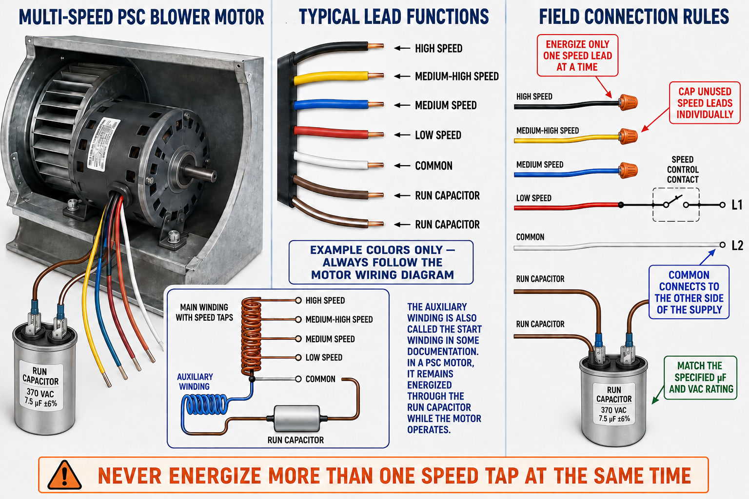
| Lead Function | Typical Role | Connection Rule |
|---|---|---|
| Selected Speed Lead | Connects the chosen main-winding tap to the controlled side of the supply. | Energize only the one speed lead called for by the equipment operating mode. |
| Unused Speed Leads | Provide alternative winding taps that are not active in the selected mode. | Insulate each unused lead separately and secure it so it cannot contact another conductor, ground, or moving part. |
| Common Lead | Completes the winding circuit to the other side of the supply. | Connect exactly as shown on the motor and equipment diagrams. |
| Capacitor Leads | Connect the specified run capacitor into the auxiliary-winding circuit. | Follow terminal markings and the motor diagram; do not infer function from color alone. |
| Grounding Conductor or Terminal | Provides equipment grounding as required by the motor and installation. | Never use it as a current-carrying common or neutral connection. |
Never Energize More Than One Speed Tap at the Same Time
Simultaneously energizing multiple speed leads can apply voltage between winding taps, produce damaging circulating current, overheat the winding, damage controls, and create a fire or shock hazard. Interlocking and switching must prevent overlap unless the motor manufacturer specifically provides another approved arrangement.
The Correct Tap Is an Equipment Requirement
Speed selection affects blower airflow, temperature rise, evaporator performance, sensible and latent capacity, refrigerant pressures, noise, and motor load. A technician should not automatically select the highest or lowest lead. Use the equipment wiring diagram, blower-performance data, approved setup procedure, and measured system conditions.
Heating and cooling modes may use different speed taps, and fan-only operation may use another. In some systems, relays or control boards transfer among taps. Verify that the previous speed connection is fully de-energized before another is energized and that replacement control contacts are suitable for the motor load.
Heating Airflow
The selected speed must maintain the equipment’s required temperature rise and airflow while respecting furnace, air-handler, and duct-system limits.
Cooling Airflow
The selected speed influences coil temperature, moisture removal, capacity, refrigerant conditions, and freeze protection.
External Static Pressure
Filters, coils, ducts, dampers, registers, and blower cleanliness affect delivered airflow and motor loading; a speed tap does not correct a restricted system.
Motor Cooling
An air-over motor depends on equipment airflow for cooling, so prolonged operation outside the blower or with restricted airflow can overheat it.
Good Running Performance but Moderate Starting Torque
PSC motors generally provide better efficiency, power factor, and running performance than comparable shaded-pole motors, and they avoid the mechanical starting switch used by resistance-start motors. Their starting torque is moderate, so they are most suitable for fans, blowers, and pumps that do not require the strong starting torque of a capacitor-start design.
Indoor Blowers
Multi-speed PSC motors have traditionally served furnaces and air handlers, with speed taps assigned to heating, cooling, and fan modes.
Condenser Fans
Single- or multi-speed PSC motors drive many propeller fans when matched to blade, rotation, airflow, ambient temperature, enclosure, and mounting.
Evaporator Fans
PSC motors are used in some refrigeration and unit-cooler applications where the motor is rated for the temperature, moisture, duty, and airflow conditions.
Pumps and Circulators
Some small pump loads use PSC motors when their torque, speed, duty, and fluid-system requirements are compatible.
Reverse the Auxiliary Relationship When the Motor Allows It
The direction of PSC starting torque depends on the phase and magnetic relationship between the main and auxiliary windings. On a motor designed for field reversal, direction is changed by reversing the auxiliary-winding connections relative to the main winding. Some motors provide a reversing plug or identified leads for this purpose.
Many HVAC/R fan motors are manufactured for one direction or have internal connections that are not intended for field modification. Always identify rotation from the specified viewing end and follow the motor diagram. Reversing both incoming supply conductors does not reverse a conventional PSC motor.
A Capacitor Problem Can Resemble a Motor or Load Problem
| Symptom | Possible Causes | Important Checks |
|---|---|---|
| Hums but Does Not Start | Failed or incorrect capacitor, low voltage, open auxiliary winding, bound load, tight bearings, incorrect wiring, or damaged motor. | Verify voltage under load, capacitor specification and condition, winding circuits, mechanical freedom, and load. |
| Starts Slowly | Weak or incorrect capacitor, low voltage, bearing drag, excessive load, winding damage, or unsuitable replacement. | Measure supply during starting and compare capacitor, current, speed, airflow, and mechanical condition with approved data. |
| Runs Hot | Wrong capacitor, overload, restricted air-over cooling, incorrect speed tap, low or high voltage, cycling, winding damage, or excessive ambient temperature. | Check current on the active lead, capacitor value, airflow, voltage, load, duty, temperature, and motor application. |
| Wrong Speed | Incorrect tap, low voltage, excessive load, wrong motor, failed winding section, control fault, or mistaken lead identification. | Use the actual diagrams and verify which single speed lead is energized in each operating mode. |
| Capacitor Fails Repeatedly | Wrong µF or VAC rating, excessive temperature, overvoltage, loose connection, incorrect motor, vibration, or winding fault. | Confirm motor-required ratings, measured voltage using an approved procedure, mounting, terminals, temperature, and motor condition. |
| Overload Cycles | Mechanical overload, restricted cooling, wrong capacitor, voltage problem, winding fault, wrong motor, frequent cycling, or high ambient temperature. | Do not treat resetting as a repair; identify the source of current or temperature rise. |
Test the Entire Motor Circuit and Driven Load
Identify and Document
Record the motor and equipment nameplates, run-capacitor requirement, lead functions, active speed, rotation, wiring, application, and reported symptoms.
Observe the System
When safe for a qualified person, check supply voltage, starting behavior, operating current, speed, rotation, airflow, sound, vibration, temperature, and control sequencing.
Control Hazardous Energy
Isolate the equipment, apply the required energy-control procedure, verify de-energization, and discharge and verify the capacitor by an approved method.
Inspect the Mechanical Load
Check bearings, shaft, blade or blower wheel, mounting, balance, clearances, belt or coupling, cleanliness, filters, coils, ducts, and airflow restrictions.
Test Isolated Components
Using approved procedures, test capacitance, inspect the capacitor, identify winding circuits, check resistance and unwanted continuity to ground, and inspect connections.
Verify the Repair
Confirm reliable starting, correct speed and rotation, one energized speed tap, normal current and voltage, acceptable temperature, secure unused leads, proper airflow, and correct control operation.
Do Not Condemn a Motor From One Capacitor Test
A failed capacitor may be the immediate fault, but voltage, motor windings, heat, mechanical load, connections, and the application may have caused that failure. Conversely, a capacitor that measures within tolerance does not prove the motor, supply, controls, or load are operating correctly.
Avoid These Errors
“The Capacitor Is Used Only to Start”
In a PSC motor, the run capacitor and auxiliary winding remain in the circuit during the entire operating period.
“Auxiliary Winding Means Start-Only”
The auxiliary winding may be called the start winding in some documents, but it remains energized through the run capacitor in a PSC motor.
“Any Close Capacitor Value Is Acceptable”
The motor is designed for a specified capacitance and tolerance. Use the required value rather than estimating or substituting by convenience.
“Capacitor VAC Must Equal Supply Voltage”
The motor specification determines the capacitor voltage rating because circuit conditions can place a voltage across the capacitor that differs from line voltage.
“Speed-Lead Colors Are Universal”
Colors vary among motors and manufacturers. Identify each lead from the actual motor diagram and nameplate.
“Two Speed Leads Produce an Intermediate Speed”
Energizing multiple taps can damage the winding and controls. Only one approved speed lead is energized at a time.
Review Questions
1. What does PSC stand for?
Answer: Permanent split capacitor.
2. Which components remain in the circuit while a PSC motor operates?
Answer: The main winding and the auxiliary winding in series with the run capacitor remain energized.
3. Why does a basic PSC motor not need a centrifugal switch?
Answer: It has no start-only winding or start capacitor to disconnect; the auxiliary winding and run capacitor remain in the circuit.
4. What two run-capacitor ratings must be matched?
Answer: The specified capacitance in microfarads and the required minimum AC voltage rating must be matched, along with the required type and tolerance.
5. Why may the auxiliary winding be called the start winding even though it remains energized?
Answer: Some documentation uses start winding as an alternate name because the winding helps establish starting torque, but PSC construction keeps it energized for running.
6. How many speed leads should be energized at one time on a conventional multi-speed PSC motor?
Answer: Only one speed lead should be energized at a time unless the manufacturer documents another approved arrangement.
7. How should unused speed leads be handled?
Answer: Each unused lead should be insulated individually and secured away from other conductors, ground, and moving parts.
8. Name four conditions other than a failed capacitor that can cause a PSC motor not to start.
Answer: Examples include low voltage, an open winding, incorrect wiring, tight bearings, a bound fan or blower, rotor damage, failed controls, or an unsuitable motor.
Lesson 7 Summary
- A PSC motor has a main winding and an auxiliary winding connected in series with a run capacitor.
- The main winding, auxiliary winding, and run capacitor remain active during starting and running.
- The run capacitor changes auxiliary-current timing and helps create phase displacement, torque, and suitable running performance.
- A basic PSC motor does not use a centrifugal switch.
- The auxiliary winding may also be called the start winding in some documentation even though it remains energized.
- The run capacitor must match the specified capacitance, tolerance, type, and minimum VAC rating.
- A start capacitor is not a substitute for a continuously rated motor run capacitor.
- Multi-speed PSC blower motors use winding taps selected by individual speed leads.
- Only one speed tap may be energized at a time unless another arrangement is specifically approved.
- Unused speed leads must be individually insulated and secured.
- Lead colors are examples rather than universal identification standards.
- Speed selection affects airflow, temperature rise, refrigeration performance, noise, motor load, and cooling.
- PSC motors generally provide moderate starting torque and are suited to many blower, fan, and pump loads.
- Replacement requires matching the complete electrical, mechanical, thermal, capacitor, speed, and control application.
- Troubleshooting must include the capacitor, windings, supply, controls, selected speed, bearings, airflow, and driven load.