Split-Phase Motors
A resistance-start split-phase motor uses two stator windings with different electrical characteristics to create the phase displacement needed for starting torque. The main winding remains energized during operation, while the higher-resistance auxiliary winding is disconnected after the motor accelerates.
This motor design does not use a capacitor. Its starting performance comes from differences between the main and auxiliary winding circuits, together with a centrifugal switch or another approved device that removes the auxiliary winding at the proper speed.
Learning Objectives
Identify the Windings
Distinguish the lower-resistance main winding from the higher-resistance auxiliary winding and explain their positions in the stator.
Explain Starting Torque
Describe how different winding resistance-to-reactance characteristics create current displacement and a rotating magnetic effect.
Explain Switch Operation
Describe how a centrifugal mechanism closes the start circuit at rest and opens it after the rotor accelerates.
Diagnose Starting Problems
Relate symptoms to the supply, windings, switch contacts, centrifugal mechanism, bearings, connections, and driven load.
Two Stator Windings Perform Different Jobs
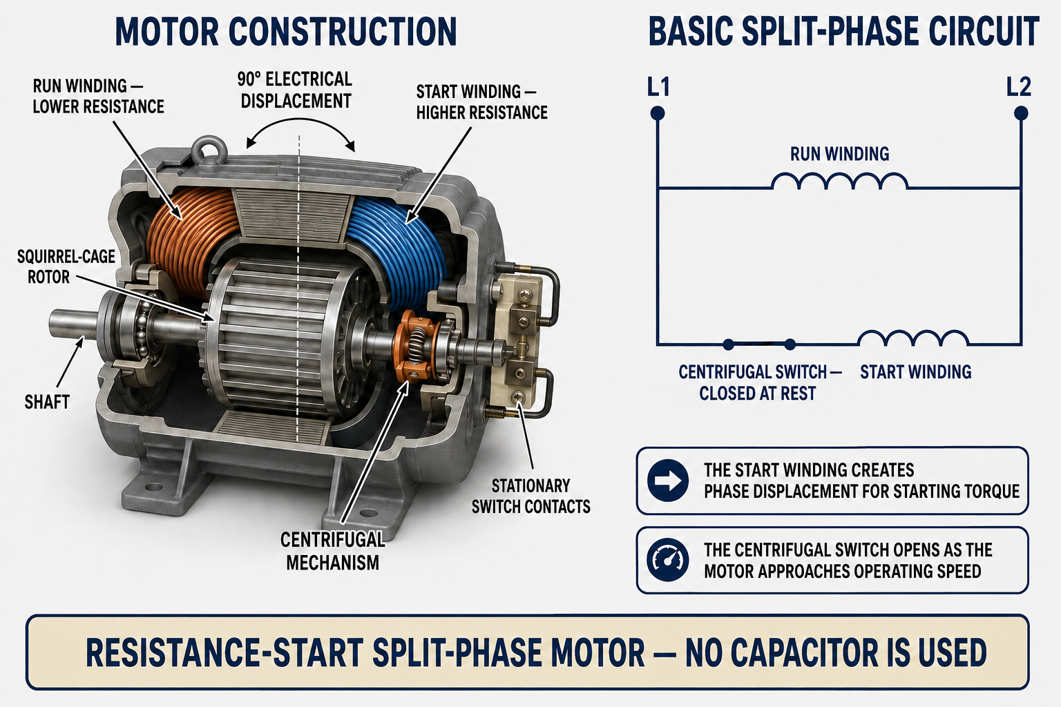
A split-phase motor is a single-phase induction motor with a main winding and an auxiliary winding displaced in magnetic position in the stator. Both windings are connected across the supply during starting. Their physical displacement and different electrical characteristics produce the magnetic sequence needed to start the squirrel-cage rotor.
The main winding, also called the run winding, is designed for continuous operation and normally has lower resistance and greater inductive reactance. The auxiliary winding, also called the start winding in this design, normally uses smaller wire and has higher resistance relative to its reactance. It is designed for short-duration starting service rather than continuous operation.
| Component | Basic Function | Service Significance |
|---|---|---|
| Main or Run Winding | Produces the primary running field and remains connected during starting and normal operation. | An open, shorted, grounded, or overheated main winding prevents normal operation. |
| Auxiliary or Start Winding | Creates a displaced magnetic effect during acceleration and is then removed from the circuit. | Because it is not designed for continuous duty, failure to disconnect it can cause rapid overheating. |
| Squirrel-Cage Rotor | Develops torque when induced rotor current interacts with the stator magnetic field. | Rotor damage, rubbing, misalignment, or a bound load can prevent acceleration. |
| Centrifugal Mechanism | Responds to shaft speed and mechanically operates the stationary switch contacts. | Sticking, wear, contamination, broken springs, or incorrect assembly can prevent proper transfer. |
| Stationary Switch | Completes the auxiliary-winding circuit at rest and opens it after acceleration. | Burned, welded, dirty, misaligned, or failed contacts can cause starting or overheating problems. |
| Shaft and Bearings | Support rotation and transfer motor torque to the load. | Bearing drag, a bent shaft, poor alignment, or excessive belt tension can extend starting time or prevent transfer speed. |
Different Winding Characteristics Create Phase Displacement
Both windings receive the same single-phase supply voltage during starting, but their currents do not reach corresponding points at exactly the same time. The main winding is more inductive, so its current lags the applied voltage more strongly. The auxiliary winding has a higher resistance-to-reactance ratio, so its current is less delayed.
The winding magnetic axes are displaced in the stator, and the winding currents are displaced in time. These two conditions create a rotating-field effect that establishes direction and produces moderate starting torque. Once the rotor is turning fast enough, the auxiliary winding is no longer needed and must be disconnected.
Power Is Applied
The closed start switch connects both the main and auxiliary windings across the single-phase supply.
Winding Currents Differ
Different winding resistance and inductive reactance cause the main- and auxiliary-winding currents to be displaced in time.
Starting Torque Develops
The displaced winding fields act at different positions and times, establishing rotation and producing torque in the squirrel-cage rotor.
The Rotor Accelerates
The motor accelerates the connected load while both windings remain energized for the brief starting interval.
The Start Circuit Opens
At the designed transfer speed, the centrifugal mechanism or approved relay opens the auxiliary-winding circuit.
The Main Winding Continues
The motor continues running on the main winding while the rotating rotor and stator field maintain torque with normal slip.
Shaft Speed Controls the Starting Circuit
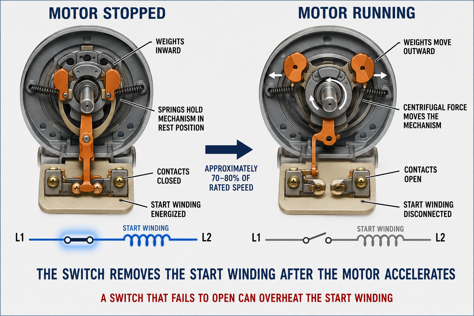
A common centrifugal switch has a rotating mechanism mounted on the shaft and stationary electrical contacts mounted inside the motor end bell. When the motor is stopped, springs hold the rotating mechanism in its rest position and the stationary contacts remain closed, completing the auxiliary-winding circuit.
As shaft speed increases, centrifugal force moves the weights outward and shifts the mechanism. At the motor’s designed transfer speed—commonly around 70 to 80 percent of rated speed for the type illustrated—the mechanism allows the stationary contacts to open and disconnect the auxiliary winding. When power is removed and speed falls, the springs return the mechanism and the contacts close for the next start.
Stopped Position
Weights are inward, springs hold the mechanism in its rest position, and the start contacts are normally closed.
Accelerating Position
Both windings remain energized while the rotor and driven load accelerate toward the switch transfer speed.
Running Position
Weights move outward, the mechanism releases or moves the contact actuator, and the start contacts open.
Stopping Position
As speed falls, spring force returns the mechanism and the contacts close in preparation for the next start.
The Start Winding Is Short-Duty
A switch that fails to open can leave the high-resistance start winding energized and cause severe overheating. A motor that cannot accelerate because of low voltage or mechanical overload may produce the same result by never reaching transfer speed.
Stuck Open and Stuck Closed Produce Different Symptoms
| Condition | Electrical Result | Likely Symptoms | Possible Causes |
|---|---|---|---|
| Contacts Fail to Close at Rest | The auxiliary winding is not energized during starting. | Motor hums, does not start, starts only under abnormal conditions, draws high current, or opens its overload. | Burned or misaligned contacts, stuck mechanism, contamination, broken spring, incorrect assembly, or open start circuit. |
| Contacts Fail to Open | The auxiliary winding remains energized after acceleration. | Click may be absent, current and temperature may remain high, the start winding may burn, or the overload may open. | Welded contacts, stuck weights, damaged actuator, contamination, incorrect assembly, or failure to reach transfer speed. |
| Contacts Chatter | The start circuit repeatedly connects and disconnects near transfer speed. | Repeated clicking, unstable current, poor acceleration, heating, vibration, or intermittent operation. | Low voltage, fluctuating speed, excessive load, weak springs, worn mechanism, loose mounting, or contact problems. |
| Motor Never Reaches Transfer Speed | The contacts may remain closed even though the switch mechanism itself is functional. | Slow acceleration, prolonged high current, overheating, overload trips, or failure to start. | Low voltage, excessive mechanical load, bearing drag, incorrect motor, winding damage, or supply problems. |
Moderate Starting Torque Fits Moderate Loads
Resistance-start split-phase motors generally develop more starting torque than shaded-pole motors but less than capacitor-start motors of similar size. They are suited to loads that accelerate without the high starting torque required by many compressors, heavily loaded pumps, or other hard-starting equipment.
Blowers and Fans
Some blowers, ventilators, and fan assemblies use split-phase motors when the load has suitable starting characteristics and the motor matches the equipment.
Small Pumps
Some circulating, condensate, and other small pumps may use this design when the pump starts under conditions within the motor’s torque capability.
Belt-Driven Loads
Light or moderate belt-driven equipment may use a split-phase motor when pulley ratio, belt tension, inertia, and running load are appropriate.
General Equipment Loads
Some machine, ventilation, and appliance loads use the design, although PSC, capacitor-start, and electronic motors have replaced it in many HVAC/R applications.
Do Not Substitute by Horsepower Alone
The replacement must match voltage, phase, frequency, horsepower, speed, starting torque, rotation, frame, shaft, mounting, duty, enclosure, ambient conditions, protection, and the driven load. A motor with the same horsepower but a different starting design may be unsuitable.
Reverse One Winding Relative to the Other
The direction of starting torque depends on the magnetic sequence between the main and auxiliary windings. On a motor designed for field reversal, direction is changed by reversing the auxiliary-winding connections relative to the main winding. Reversing both windings together leaves their relationship unchanged and does not reverse the motor.
Not every split-phase motor provides accessible reversible leads. Some are manufactured for one rotation, some use internal connections, and the equipment may require a specific direction. Follow the motor connection diagram and confirm clockwise or counterclockwise rotation from the stated viewing end.
Separate Start-Circuit, Supply, and Load Problems
Identify and Document
Record the nameplate, wiring diagram, lead connections, rotation, motor application, driven load, and reported symptoms before disconnecting conductors.
Inspect Operation
When safe and appropriate for a qualified person, observe starting time, sound, rotation, current, supply voltage, switch transfer, vibration, and load behavior.
Control Hazardous Energy
Follow the required energy-control procedure, isolate all applicable sources, verify de-energization, and wait for moving parts to stop before opening the motor or load.
Check the Mechanical System
Inspect bearings, shaft, coupling, belt tension, pulley alignment, fan or blower, pump, clearances, and the load for binding or excessive inertia.
Test the Isolated Circuits
Using approved procedures, check the main winding, auxiliary winding, switch contacts, leads, and unwanted continuity to the motor frame or ground.
Verify the Completed Repair
Confirm reliable acceleration, proper switch transfer, correct rotation, normal current and voltage, acceptable temperature, quiet operation, and correct equipment performance.
Do Not Operate an Open Motor Energized
A removed end bell exposes live contacts and a rotating centrifugal mechanism. Inspect and test internal components only with hazardous energy controlled unless an approved manufacturer procedure and suitable guarded test equipment specifically provide otherwise.
Resistance Readings Identify Conditions, Not Complete Performance
With the motor isolated and the applicable leads identified, an ohmmeter may show continuity through both windings. The auxiliary winding normally has higher resistance than the main winding, but exact readings depend on the motor design, wire temperature, meter, lead arrangement, and whether other components remain connected.
A resistance reading within an expected range does not prove that the motor will develop correct torque under load. Shorted turns may cause only a small resistance change, switch problems can be speed-dependent, and mechanical drag may appear only during operation. Use manufacturer data and combine resistance tests with inspection and operating measurements.
Open Main Winding
The motor will not run normally. Depending on the circuit, an attempted start may produce no operation or abnormal start-winding current.
Open Auxiliary Circuit
The motor may hum without starting because the directional starting field is absent. The open may be in the winding, contacts, lead, connection, or protective device.
Grounded Winding
Unwanted continuity between a winding and the motor frame indicates an insulation fault requiring the motor to remain out of service.
Shorted Turns
The motor may draw excessive current, produce weak torque, run hot, or trip protection even though a basic continuity test shows a complete circuit.
Avoid These Errors
“Every Split-Phase Motor Has a Capacitor”
The basic resistance-start split-phase motor uses winding resistance and reactance differences and does not use a capacitor.
“The Start Winding Runs Continuously”
In this motor, the auxiliary winding is short-duty and must be disconnected after acceleration.
“Closed Contacts Prove the Switch Is Stuck”
The contacts should be closed while the motor is stopped and during early acceleration. They open only after the motor reaches transfer speed.
“A Burned Start Winding Proves Welded Contacts”
Welded contacts are one cause, but low voltage, overload, bearing drag, or another condition that prevents transfer speed can also leave the start winding energized too long.
“Swapping the Line Leads Reverses Rotation”
Direction changes only when one winding is reversed relative to the other according to the motor diagram.
“Continuity Proves the Motor Is Good”
Continuity does not prove correct phase displacement, insulation under stress, switch transfer, torque, current, bearing condition, or performance under load.
Review Questions
1. What two stator windings are used in a split-phase motor?
Answer: It uses a main or run winding and an auxiliary or start winding.
2. Which winding normally has the higher resistance?
Answer: The auxiliary or start winding normally has higher resistance than the main winding.
3. How does a resistance-start split-phase motor create starting phase displacement?
Answer: Different main- and auxiliary-winding resistance-to-reactance characteristics cause their currents and magnetic effects to be displaced in time.
4. Does the basic resistance-start split-phase motor use a capacitor?
Answer: No. It produces starting phase displacement through winding design.
5. What is the centrifugal switch position when the motor is stopped?
Answer: Its start contacts are normally closed so the auxiliary winding will be energized during the next start.
6. What happens when the motor reaches the switch transfer speed?
Answer: The centrifugal mechanism causes the contacts to open and disconnect the auxiliary winding.
7. What can happen if the start contacts fail to open?
Answer: The short-duty auxiliary winding remains energized, causing excessive heating that can damage the winding or operate the overload.
8. Why might functional contacts remain closed even when the switch is not defective?
Answer: Low voltage, excessive load, bearing drag, winding damage, or another problem may prevent the motor from reaching the speed at which the switch opens.
Lesson 6 Summary
- A split-phase motor has a main winding and an auxiliary winding displaced in magnetic position.
- The main winding is also called the run winding and remains energized during normal operation.
- The auxiliary winding is also called the start winding and is used only during acceleration in this design.
- The auxiliary winding normally has a higher resistance-to-reactance ratio than the main winding.
- Different winding characteristics displace the two winding currents in time and create starting torque.
- A resistance-start split-phase motor does not use a capacitor.
- At rest, the centrifugal switch contacts are closed and both windings are connected across the supply.
- After the motor reaches its designed transfer speed, the switch opens and disconnects the auxiliary winding.
- As the motor stops, springs return the mechanism and close the contacts for the next start.
- Contacts that fail to close prevent normal starting, while contacts that fail to open can overheat the start winding.
- A motor that cannot reach transfer speed may keep a functional start switch closed too long.
- Resistance-start motors provide moderate starting torque between typical shaded-pole and capacitor-start performance.
- Direction is changed by reversing one winding relative to the other when the motor is designed for field reversal.
- Continuity alone does not prove that the motor, switch, bearings, supply, or load will operate correctly.
- Troubleshooting must evaluate the entire supply, starting circuit, motor, and driven load.