Hermetic Compressor Motors and Terminals
In a hermetic compressor, the electric motor and compressor mechanism operate inside the same welded shell. The internal motor drives the compressor directly without an external shaft or shaft seal, while sealed electrical terminals carry power through the shell.
Single-phase hermetic compressors commonly provide common, start, and run terminals identified as C, S, and R. These terminals connect the internal main and auxiliary windings to the external overload, capacitors, relays, contactor, and control circuit. Correct identification and safe handling are essential because the terminal assembly is both electrically energized and exposed to system pressure.
Learning Objectives
Explain Hermetic Construction
Describe how the motor, compressor mechanism, bearings, oil, and refrigerant occupy the same sealed shell.
Identify C, S, and R
Explain the common, start, and run terminal functions and their connection to the internal motor windings.
Recognize Terminal Hazards
Describe electrical, stored-energy, refrigerant-pressure, oil-release, ignition, and terminal-venting hazards.
Prepare for Electrical Diagnosis
Identify the information and safety steps required before winding-resistance and insulation tests are performed.
The Motor and Compressor Share One Sealed Shell
A hermetic compressor encloses the stator, rotor, shaft, bearings, compression mechanism, oil, and internal wiring within a welded steel shell. The motor shaft drives the compressor mechanism directly. Eliminating an external shaft seal reduces a potential refrigerant-leak point but prevents ordinary external access to the internal motor and mechanism.
The illustration shows a typical suction-cooled hermetic reciprocating compressor. Cool suction gas enters the shell and flows around or through the motor before reaching the compression mechanism, helping remove motor heat. Other compressor designs route refrigerant differently, so the actual cooling and gas-flow path must be determined from manufacturer information.
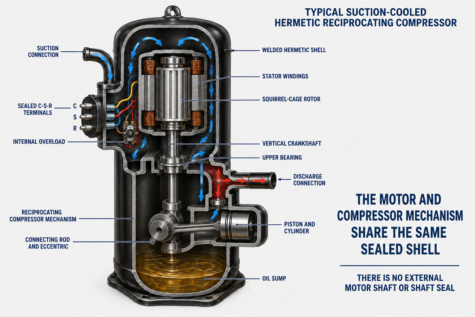
| Internal Component | Function | Service Significance |
|---|---|---|
| Stator Windings | Create the magnetic fields that operate the compressor motor. | Open, shorted, or grounded windings generally require replacement of the sealed compressor assembly. |
| Squirrel-Cage Rotor | Develops motor torque through induction and turns the internal shaft. | A mechanically locked rotor or damaged mechanism can produce locked-rotor current even when winding continuity exists. |
| Crankshaft or Drive Shaft | Transfers motor torque directly to the compressor mechanism. | There is no external shaft available for a technician to turn on a welded hermetic compressor. |
| Bearings and Oil System | Support moving parts and provide lubrication and cooling. | Oil loss, refrigerant dilution, contamination, flooding, overheating, or inadequate return can damage both motor and mechanism. |
| Compression Mechanism | Raises refrigerant pressure and moves refrigerant through the system. | Mechanical damage or abnormal pressure conditions can overload an electrically intact motor. |
| Internal Wiring and Protection | Connect the motor windings to the sealed terminals and may provide internal thermal or current protection. | A protector may open internally and later reset; its configuration and test procedure depend on the compressor. |
| Glass-to-Metal Terminal Assembly | Carries electrical conductors through the pressure shell while maintaining a refrigerant seal. | Damage, overheating, corrosion, loose connections, or electrical faults can create shock, leakage, arcing, and terminal-venting hazards. |
Compressor Construction Determines Service Access
Hermetic Compressor
The motor and compressor are sealed within a welded shell. Internal motor or mechanical repairs are not normally performed in the field.
Semi-Hermetic Compressor
The motor and compressor share a sealed refrigerant housing that can be opened with approved procedures for internal service and component replacement.
Open-Drive Compressor
An external motor drives the compressor through a shaft, coupling, belt, or other arrangement, and a shaft seal is required where the compressor shaft passes through the housing.
C, S, and R Connect to Two Internal Windings
The main or run winding is connected between common and run. The auxiliary or start winding is connected between common and start. Common is the internal junction shared by both windings. External wires and components connect these three sealed terminal pins to the approved compressor circuit.
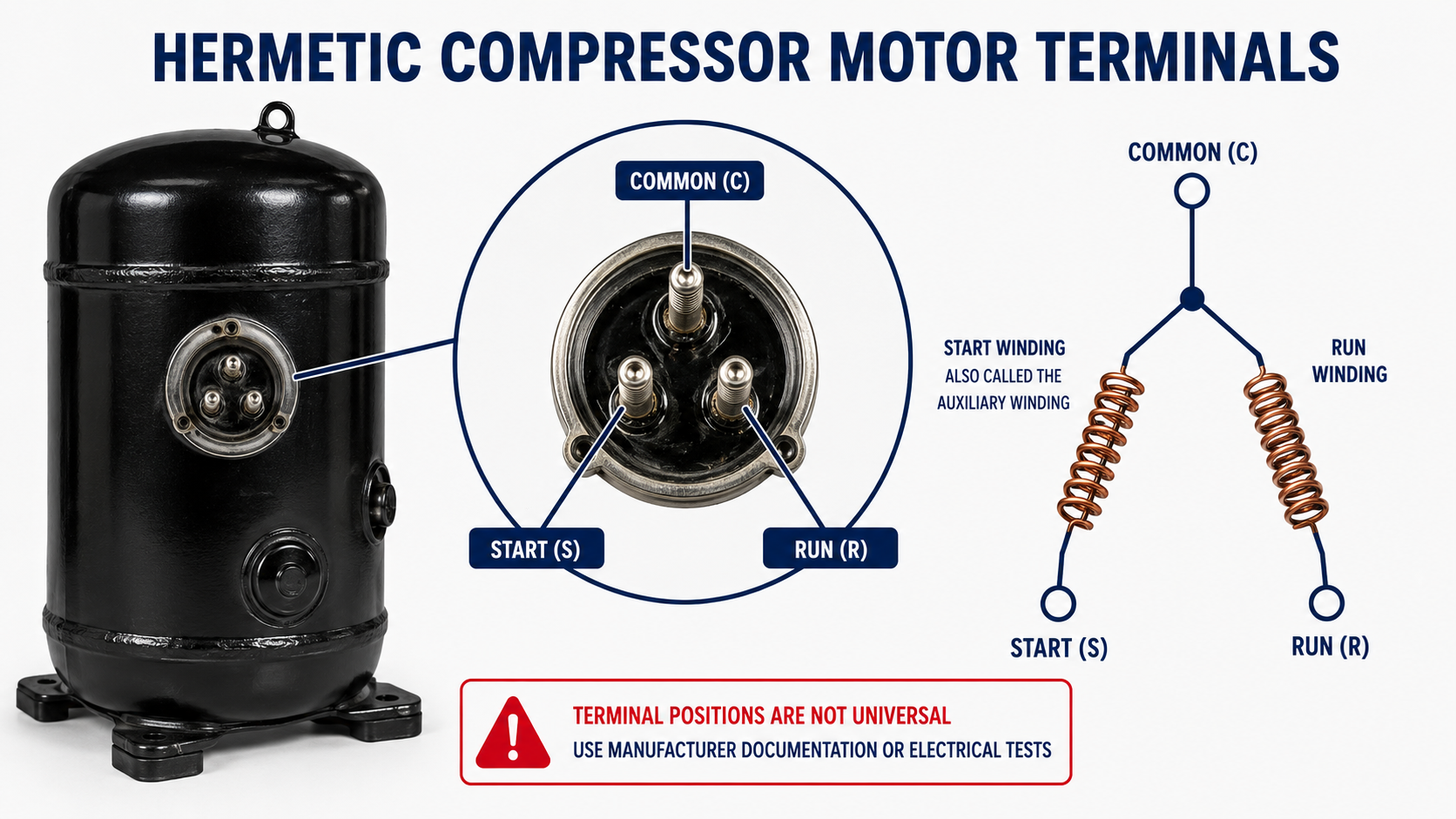
| Terminal | Internal Connection | Typical External Role |
|---|---|---|
| Common (C) | Shared junction of the main and auxiliary windings. | Often connects through an internal or external overload to one side of the supply, depending on the approved circuit. |
| Start (S) | External end of the auxiliary or start winding. | Connects to the capacitor and starting components required by the compressor design. |
| Run (R) | External end of the main or run winding. | Connects to the running supply circuit and may be associated with a current-relay coil or run capacitor circuit. |
Physical Location Is Not a Reliable Identification Method
Many training diagrams show the common terminal above start and run, but actual terminal orientation varies with compressor manufacturer, model, mounting position, and viewing direction. The compressor may be rotated in the equipment, and a terminal plate may be viewed from the compressor side or connector side.
Do not identify C, S, and R from a memorized triangle pattern. Look for markings on the terminal plate, molded plug, cover, compressor label, or wiring diagram. When documentation and markings are unavailable, qualified technicians may identify isolated single-phase windings through resistance relationships using an approved procedure, as explained in Lesson 10.
Photograph and Label Before Disconnecting
Record every wire, connector, overload, capacitor, relay, terminal marking, and plug orientation before removal. Do not rely on wire color alone, and do not force a connector onto pins in an unverified orientation.
The Compressor Terminals Do Not Identify the Entire Motor Type
The same C-S-R terminal arrangement can be used with PSC, CSIR, CSCR, and manufacturer-specific single-phase compressor circuits. The terminal letters identify winding connections, while the external capacitors, relays, overloads, and wiring determine how those windings are used during starting and running.
PSC Compressor Circuit
The run capacitor and auxiliary winding remain energized during starting and running. Some approved applications add a start-assist device.
CSIR Compressor Circuit
The start capacitor and auxiliary winding are energized during starting and disconnected after acceleration.
CSCR Compressor Circuit
The start capacitor disconnects after acceleration, while the run capacitor and auxiliary winding remain energized.
Electronic Starting or Protection
An approved module may control starting, monitor current or temperature, delay restart, or interpret winding-circuit conditions according to manufacturer logic.
Refrigeration Conditions Affect Motor Temperature
In a suction-gas-cooled compressor, returning refrigerant vapor helps remove heat from the motor. Inadequate mass flow, excessive superheat at the compressor, low charge, a restricted suction path, operation outside the approved envelope, or repeated overload cycling can reduce cooling and raise winding temperature.
Other compressor designs may rely more heavily on shell heat transfer, oil circulation, discharge-gas routing, or manufacturer-specific cooling paths. Never assume that all hermetic compressors are cooled in the same way. Diagnose the complete refrigeration system and use the compressor operating envelope and application data.
Suction Conditions
Abnormal suction pressure, temperature, superheat, or flow can affect motor cooling, oil return, capacity, and compressor temperature.
Discharge Conditions
High compression ratio, high condensing pressure, excessive discharge temperature, or restricted flow can increase motor load and internal heat.
Oil and Refrigerant
Oil dilution, migration, flooding, loss of oil return, contamination, or incorrect refrigerant and oil can damage bearings, windings, and the compression mechanism.
Starting Frequency
Short cycling and rapid restart increase winding heat and may attempt to start the compressor before pressure and protection conditions are ready.
An Open Protector Can Resemble an Open Winding
Many single-phase hermetic compressors use an internal or external overload associated with the common circuit, but protector arrangements vary. Some sense current and temperature, some respond to shell or winding temperature, and some compressors use electronic modules with embedded sensors.
If a protector is open, resistance measurements may show no continuity through one or both winding paths even though the windings themselves have not opened. The protector may reset after cooling, but reset does not establish that the compressor is safe or serviceable. Identify and correct the cause of the excessive current or temperature.
| Possible Cause of Protector Operation | Examples |
|---|---|
| Starting Failure | Low voltage, failed capacitor or relay, incorrect wiring, excessive pressure difference, locked mechanism, or damaged winding. |
| Electrical Overload | High or low voltage, loose connection, contactor voltage drop, wrong components, shorted turns, or repeated starts. |
| Refrigerant-System Load | High condensing pressure, restriction, low suction pressure, high compression ratio, floodback, or operation outside the envelope. |
| Cooling Problem | Low refrigerant mass flow, excessive return-gas temperature, high ambient, blocked heat transfer, or inadequate equipment airflow. |
| Mechanical Problem | Bearing damage, lubrication failure, internal wear, liquid slugging, contamination, or a locked compressor mechanism. |
Do Not Cool a Compressor by Unsafe Means
Follow manufacturer procedures and allow the compressor to cool naturally or by an approved method. Do not apply water, refrigerant, ice, or other materials to force an overload reset, and never bypass internal or external protection.
The Terminal Assembly Is Part of a Pressurized Shell
If an electrical terminal pin loses its pressure seal, refrigerant, oil, and debris can be expelled from the compressor. Electrical arcing or another ignition source can ignite the released mixture, and flames may project outward. This event is known as terminal venting.
The approved terminal cover or molded plug helps protect against electric shock and can help contain spray and flame, although it cannot eliminate the hazard. The cover or plug must be correctly installed whenever the compressor is energized. Keep clear of the terminal area during energization and follow the compressor manufacturer’s current safety instructions.
Never Simply Reset and Re-Energize After an Electrical Trip
A tripped breaker, blown fuse, damaged terminal, burned connector, or evidence of an electrical fault requires investigation before energization. Disconnect all power, use lockout/tagout procedures, verify de-energization, inspect and test as directed, and replace damaged covers, plugs, wiring, and components with approved parts.
Terminal Cover
Use the correct undamaged cover, gasket, molded plug, fasteners, and routing arrangement specified for the compressor.
Connections
Inspect for looseness, corrosion, overheating, pitting, cracked insulation, damaged pins, and incorrect connector fit without bending or stressing the sealed terminals.
Pressure and Refrigerant
Remember that the terminal plate is exposed to system pressure and may contain a flammable or mildly flammable refrigerant depending on the equipment.
Qualified Service
Electrical and refrigeration tests must be performed by qualified persons using appropriate PPE, rated instruments, approved procedures, and applicable safety requirements.
Isolate and Document Before Measuring Resistance
Identify the Compressor
Record the model, serial number, voltage, phase, refrigerant, equipment schematic, terminal diagram, overload, capacitors, relay, and electronic-module information.
Control All Energy
Disconnect and lock out electrical power, verify de-energization, control stored electrical energy, and address pressurized-system and refrigerant hazards.
Discharge and Verify Capacitors
Use the manufacturer’s approved discharge procedure and verify the absence of hazardous voltage before touching capacitor or compressor terminals.
Document and Disconnect
Photograph, label, and remove external wires and components as required so the compressor windings are isolated without damaging the terminal pins.
Inspect the Terminal Assembly
Stop if pins, seals, connectors, covers, or surrounding materials show damage, overheating, arcing, looseness, or evidence of leakage.
Select the Correct Tests
Use manufacturer-approved resistance, insulation, and ground-fault procedures appropriate to the compressor, protector, electronic module, refrigerant, and system condition.
Avoid These Errors
“Common Is Ground”
Common is the internal junction of the two windings. It is a current-carrying motor terminal and must not be confused with the compressor shell or equipment grounding conductor.
“The Top Pin Is Always Common”
Terminal positions are not universal. Orientation, viewing direction, and compressor construction vary.
“C-S-R Identifies the Motor Type”
The letters identify winding connections, but PSC, CSIR, and CSCR circuits can all use C-S-R terminals.
“An Open Reading Proves a Burned Winding”
An open overload, disconnected protector, poor terminal connection, or test setup can interrupt continuity. Follow the compressor’s diagnostic procedure.
“Continuity Proves the Compressor Is Good”
Continuity does not prove correct resistance relationships, insulation integrity, starting torque, free mechanical operation, or acceptable refrigerant-system conditions.
“The Terminal Cover Is Optional”
The approved cover or molded plug is a safety component and must be installed correctly whenever the compressor is energized.
Review Questions
1. Why is the compressor called hermetic?
Answer: The motor and compressor mechanism are sealed together inside a welded shell that is part of the refrigerant system.
2. What is the advantage of having no external compressor shaft?
Answer: It eliminates the external rotating shaft seal as a potential refrigerant-leak point, although internal parts are not ordinarily field-accessible.
3. Which winding is connected between C and R?
Answer: The main or run winding is connected between common and run.
4. Which winding is connected between C and S?
Answer: The auxiliary or start winding is connected between common and start.
5. Is the common terminal the same as electrical ground?
Answer: No. Common is a current-carrying internal winding junction; ground is the equipment grounding connection to the compressor shell and equipment.
6. Why should terminal position not be used as the sole identification method?
Answer: Terminal arrangements and viewing orientations vary by compressor manufacturer and model.
7. What is terminal venting?
Answer: It is the release of pressurized refrigerant, oil, and debris when a compressor terminal pin loses its seal; electrical arcing or another source may ignite the released mixture.
8. Why can an open protector produce misleading winding readings?
Answer: If the protector interrupts the common circuit, one or both winding paths may appear open even when the winding conductors themselves remain intact.
Lesson 9 Summary
- A hermetic compressor encloses the motor and compressor mechanism in the same welded shell.
- The internal shaft drives the compressor directly, so there is no external motor shaft or shaft seal.
- The motor, compressor mechanism, refrigerant, and oil share the sealed internal environment.
- The illustrated reciprocating compressor is suction-gas cooled, but refrigerant-flow and motor-cooling paths vary by design.
- The main or run winding is connected between common and run.
- The auxiliary or start winding is connected between common and start.
- Common is the shared winding junction, not electrical ground.
- Terminal positions are not universal and must be confirmed from markings, documentation, or approved tests.
- C-S-R terminals can be used with PSC, CSIR, CSCR, and other approved single-phase circuits.
- Internal and external protector configurations vary, and an open protector can affect resistance readings.
- Refrigerant conditions, cooling, lubrication, pressure, cycling, and mechanical load affect motor temperature and current.
- A damaged terminal seal can release pressurized refrigerant, oil, and debris in a terminal-venting event.
- Electrical arcing or another ignition source may ignite released refrigerant and oil.
- The approved terminal cover or molded plug must be correctly installed whenever the compressor is energized.
- Winding tests require energy isolation, capacitor discharge and verification, documented wiring, isolated terminals, and manufacturer-approved procedures.