Compressor Motor Winding Resistance Tests
Winding-resistance tests help a technician identify unmarked single-phase compressor terminals and detect open, grounded, or seriously unbalanced winding circuits. The test is useful only when the compressor is completely isolated and the readings are interpreted with the motor design, winding temperature, meter limitations, and manufacturer information in mind.
This lesson develops a repeatable procedure for testing conventional single-phase C-S-R compressors and conventional three-lead three-phase compressors. Inverter-driven, electronically commutated, part-winding, and multi-lead compressors require manufacturer-specific procedures.
Learning Objectives
Prepare a Safe Test
Isolate all power, discharge capacitors, disconnect external conductors, and verify the compressor is de-energized before measuring resistance.
Identify C, S, and R
Use the three resistance readings on a conventional single-phase compressor to identify common, start, and run.
Evaluate Three-Phase Balance
Compare all three phase-to-phase readings on a conventional three-lead three-phase compressor.
Interpret Results Correctly
Distinguish winding continuity, resistance balance, insulation-to-shell condition, and faults that resistance tests cannot prove.
What a Resistance Test Can—and Cannot—Tell You
A resistance test applies a small test current from the meter and measures opposition through the isolated winding circuit. It can reveal continuity, an open circuit, the relative resistance of single-phase windings, and substantial imbalance among comparable three-phase paths.
A normal resistance reading does not prove that a compressor will start, develop torque, or operate correctly under load. A winding may fail only when hot or under operating voltage, and a mechanically locked compressor can have electrically continuous windings. A standard ohmmeter also may not detect a small number of shorted turns.
Prepare the Compressor Before Testing
Terminal Venting Can Cause Severe Injury
A damaged compressor terminal can release pressurized refrigerant, oil, and debris, and the mixture may ignite from an arc or nearby ignition source. Never energize a compressor with the terminal cover or molded plug removed. Disconnect all power, use required lockout/tagout procedures, discharge capacitors, verify zero voltage, and inspect the terminal area before touching or removing connections.
Identify Every Source
Use the equipment schematic to locate line power, control power, crankcase-heater power, stored capacitor energy, and any separate or backfed source.
De-Energize and Verify
Open all required disconnecting means, apply the required energy-control procedure, discharge capacitors by the approved method, and verify absence of voltage with a properly rated tester.
Document Connections
Photograph and label wires, plugs, overloads, modules, relays, and terminal orientation before disconnecting them.
Isolate the Windings
Remove all external conductors and approved removable devices from the compressor terminals so no parallel circuit can alter the readings.
Do not reset a tripped breaker or replace a blown fuse and immediately re-energize the compressor. First perform the appropriate electrical checks because the protective-device operation may indicate a compressor or circuit fault.
Small Resistances Require Careful Technique
Compressor winding resistance may be only a few ohms or less. Test-lead resistance, dirty terminal contact, changing probe pressure, and winding temperature can therefore materially affect the result. Use a meter with suitable low-resistance resolution, check the leads together, and use the meter’s relative or zero function when appropriate.
| Influence | Possible Effect | Good Practice |
|---|---|---|
| Test Leads | Lead resistance adds to every two-wire reading. | Measure the shorted-lead value and compensate as the meter manufacturer directs; precision work may require a four-wire instrument. |
| Contact Condition | Oxidation, oil, dirt, or weak probe pressure can make readings high or unstable. | Inspect terminals and use firm, repeatable contact without damaging the pins or glass-to-metal seal. |
| Winding Temperature | Copper resistance increases as temperature increases. | Compare readings taken at the same stabilized temperature and use manufacturer correction data when specified. |
| External Circuits | Capacitors, relays, modules, protectors, or wiring can create false paths. | Completely isolate the compressor terminals before testing. |
| Meter Resolution | A general-purpose meter may not resolve meaningful differences at very low resistance. | Use suitable test equipment and compare with manufacturer data rather than relying on displayed digits alone. |
Measure All Three Terminal Pairs
A conventional single-phase compressor has a main winding between common and run and an auxiliary winding between common and start. The auxiliary winding is also commonly called the start winding. Because the start winding normally has greater resistance than the run winding, the three isolated readings have a predictable relationship.
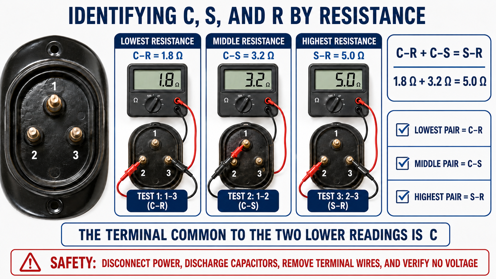
| Relative Reading | Terminal Pair | Reason |
|---|---|---|
| Lowest | C to R | The main or run winding normally uses heavier wire and has lower resistance. |
| Middle | C to S | The auxiliary or start winding normally has greater resistance than the run winding. |
| Highest | S to R | Current from S to R passes through both windings in series through their common junction. |
Identify Unmarked Terminals Without Guessing Their Position
- Assign temporary numbers. Label the isolated pins 1, 2, and 3 without assuming which one is common, start, or run.
- Record every pair. Measure 1-2, 2-3, and 1-3 using the same meter range and contact technique.
- Find the highest reading. That pair is S-R because it includes both windings in series. The terminal not included in the highest pair is C.
- Start from common. Of the two readings that include C, the lower reading identifies C-R and the higher identifies C-S.
- Check the relationship. Confirm that the two lower readings add to approximately the highest reading.
- Label and verify. Mark C, S, and R, then compare the result with the compressor diagram, molded connector, or manufacturer data before reconnecting the circuit.
In the illustrated example, the highest reading is 5.0 Ω between terminals 1 and 3, so terminal 2 is common. From terminal 2, the 1.8 Ω path identifies run and the 3.2 Ω path identifies start. The physical triangle orientation was never used to make the identification.
Patterns Suggest Faults, but Context Matters
| Observed Pattern | Possible Meaning | Next Action |
|---|---|---|
| Three stable readings follow the expected relationship. | Both winding paths have continuity and the terminals can be identified. | Compare actual values with manufacturer data and continue the full diagnosis. |
| One pair is open while the other two have continuity. | An open winding or internal connection may interrupt that path. | Account for the protector arrangement, winding temperature, and manufacturer procedure before condemning the compressor. |
| All three pairs read open. | An open common connection, open internal protector, disconnected test contact, or multiple open circuits may be present. | Allow an overheated compressor to cool when appropriate, verify the meter and contacts, and follow manufacturer instructions. |
| Readings are unstable or do not add approximately. | Poor contact, external parallel paths, damaged connections, an internal fault, or inadequate meter resolution may be involved. | Re-isolate the compressor, verify lead compensation and contact quality, then compare with approved data. |
| Resistance is unexpectedly low. | The meter may be showing lead resistance, or a winding fault may exist. | Do not diagnose shorted turns from one DMM reading; use manufacturer values and additional electrical and operating tests. |
Winding Resistance and Insulation Resistance Are Different Tests
After the phase-to-phase or terminal-to-terminal readings, test each compressor terminal to a clean, approved point on the compressor shell using the manufacturer-specified method. Any confirmed electrical continuity between an isolated winding terminal and the shell indicates a ground-fault path.
An ordinary ohmmeter that displays OL does not prove that the insulation will remain sound at operating voltage. An insulation-resistance tester can apply a much higher test voltage, but it must be used only at the voltage and under the conditions approved by the compressor and equipment manufacturers. Disconnect sensitive electronics before an approved insulation test; an improper test can damage inverter drives, protection modules, or other electronic components.
Never Megger Through Electronics
Do not apply insulation-test voltage through an inverter, electronic protector, ECM module, control board, or connected sensor circuit. Use the exact isolation and test procedure specified for that equipment.
Compare All Three Phase-to-Phase Readings
On a conventional three-lead three-phase compressor, measure T1-T2, T2-T3, and T1-T3 after complete isolation. Because the three winding paths are designed as a balanced set, the readings should be approximately equal when measured with the same technique and at the same winding temperature.
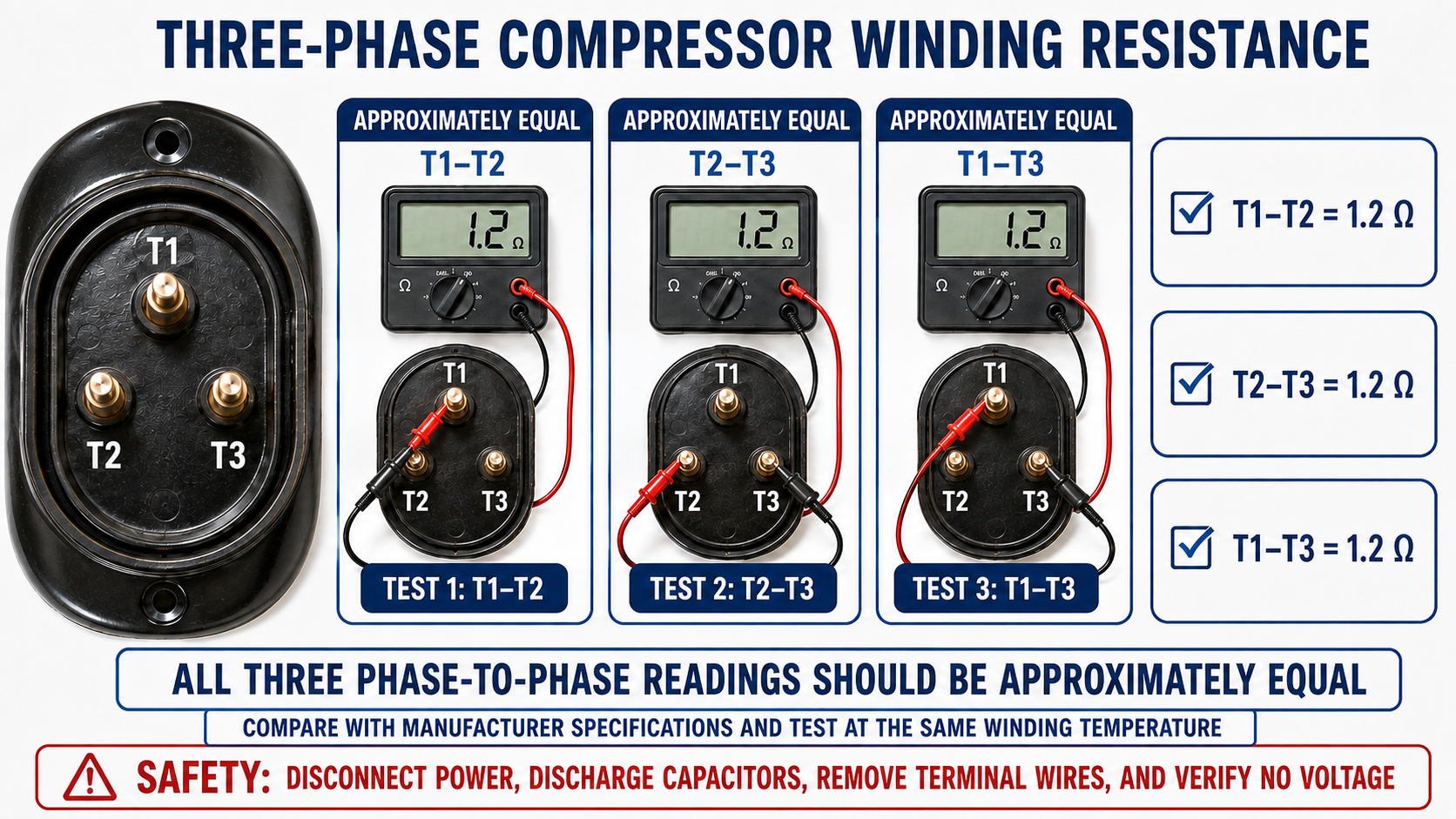
There is no universal acceptable resistance or imbalance percentage for every compressor. Absolute readings depend on horsepower, voltage, winding connection, design, temperature, meter accuracy, and terminal condition. Record all values and compare them with the compressor manufacturer’s published data.
Single-Phase and Three-Phase Patterns
| Feature | Conventional Single-Phase C-S-R | Conventional Three-Lead Three-Phase |
|---|---|---|
| Number of pair readings | Three | Three |
| Expected pattern | Lowest C-R, middle C-S, highest S-R | All three phase-to-phase readings approximately equal |
| Mathematical check | C-R + C-S ≈ S-R | T1-T2 ≈ T2-T3 ≈ T1-T3 |
| Terminal identification | Relative readings can identify C, S, and R on the applicable design. | Resistance balance does not establish phase rotation. |
| Manufacturer data | Required to judge actual resistance and special protector arrangements. | Required to judge actual resistance, tolerance, and lead configuration. |
Avoid These Diagnostic Mistakes
Testing Through Components
Connected capacitors, relays, contactors, overloads, modules, and wiring can create misleading readings. Isolate the compressor first.
Ignoring Lead Resistance
A fraction of an ohm in the leads can be significant when the winding itself measures near one ohm.
Guessing Terminal Position
The familiar terminal triangle is not a universal orientation. Use markings, documentation, and verified electrical relationships.
Condemning a Hot Compressor
An internal protector may be open after an overload. Follow the approved cooling and retest procedure before reaching a conclusion.
Calling Every Low Reading a Short
Normal compressor windings can have very low resistance. A standard DMM cannot conclusively identify a small turn-to-turn short.
Using a Megohmmeter Indiscriminately
High test voltage can damage connected electronics, and acceptance criteria depend on the specific compressor and test conditions.
A Repeatable Diagnostic Process
- Identify the compressor model, phase, voltage, terminal arrangement, approved test method, and manufacturer resistance information.
- De-energize all sources, apply required energy-control procedures, discharge capacitors, and verify zero voltage.
- Inspect the terminal area for damage, overheating, contamination, loose connections, and signs of venting risk.
- Document and disconnect all external conductors so the winding circuit is isolated.
- Check the meter, lead resistance, range, resolution, and contact repeatability.
- Measure and record every terminal pair at the same winding temperature.
- Evaluate the applicable single-phase relationship or three-phase balance.
- Perform the approved terminal-to-shell or insulation-resistance test with electronics isolated.
- Compare results with manufacturer data and the rest of the system diagnosis before deciding that the compressor has failed.
- Reconnect exactly as documented, reinstall the approved molded plug and terminal cover, and complete required operational checks.
Review Questions
1. Why must all external wires be removed before winding resistance is measured?
Connected components and wiring can create parallel or alternate paths that change the meter reading.
2. Which pair has the highest resistance on a conventional C-S-R compressor?
S to R, because that path includes the start and run windings in series through common.
3. How is common found when the terminals are unmarked?
Find the highest-resistance pair; the terminal not included in that pair is common.
4. If C-R is 1.6 Ω and C-S is 2.9 Ω, what should S-R measure approximately?
Approximately 4.5 Ω, subject to measurement tolerance and test conditions.
5. What pattern is expected on a conventional three-lead three-phase compressor?
T1-T2, T2-T3, and T1-T3 should be approximately equal.
6. Does a normal ohmmeter reading prove that the compressor is mechanically free?
No. A locked compressor can have windings with normal continuity and resistance.
7. Why should readings be compared at the same winding temperature?
Copper resistance changes with temperature, so temperature differences can be mistaken for electrical differences.
8. Why is an OL reading from a standard ohmmeter to the shell not a complete insulation test?
The meter uses a low test voltage and may not reveal insulation that fails under operating voltage; use only the manufacturer-approved insulation test.
Key Takeaways
- Completely isolate the compressor and control hazardous energy before resistance testing.
- On a conventional single-phase compressor, C-R is lowest, C-S is middle, and S-R is highest.
- The single-phase check is C-R + C-S ≈ S-R; the auxiliary winding is also called the start winding.
- On a conventional three-lead three-phase compressor, all three phase-to-phase readings should be approximately equal.
- Lead resistance, terminal contact, meter resolution, and winding temperature can significantly affect low-ohm measurements.
- Winding resistance, insulation resistance, and mechanical condition are different parts of the diagnosis.
- Manufacturer information governs acceptable values, tolerances, protector arrangements, and special compressor procedures.