Multi-Speed, Dual-Voltage, and Reversing Motor Connections
HVAC/R motors often provide several external leads so one motor can supply more than one operating speed, connect to more than one supply voltage, or rotate in either direction. Those leads are not interchangeable. Each one reaches a specific winding point, and an incorrect connection can produce the wrong airflow, excessive current, overheating, reverse rotation, or immediate winding damage.
This lesson explains the principles behind multi-speed PSC blower motors, series-parallel dual-voltage windings, and reversible single-phase motors. The principles help technicians understand a diagram; they do not replace the exact nameplate or manufacturer connection diagram for the motor being installed or serviced.
Learning Objectives
Select a Speed Tap
Explain how a multi-speed PSC blower motor uses winding taps and why only the intended speed lead is energized.
Connect Dual Voltage
Relate parallel winding connections to the lower nameplate voltage and series connections to the higher voltage.
Explain Reversal
Describe why reversing one winding relative to the other reverses an applicable single-phase motor.
Use Connection Information
Read the motor nameplate and connection diagram instead of assuming functions from wire colors or memorized lead numbers.
De-Energize Before Changing Motor Leads
A Misconnected Motor Can Start Unexpectedly or Fail Immediately
Before opening a motor connection compartment or moving any lead, identify every power source, disconnect and lock out power as required, discharge capacitors by the approved method, and verify absence of voltage with a properly rated tester. Photograph and label the original connections before disturbing them.
Automatic HVAC/R controls may restart a motor without warning. Fan compartments also contain rotating wheels, belts, pulleys, and sharp sheet-metal edges. Restore all guards, panels, grounding connections, strain relief, terminal covers, and unused-lead insulation before operational testing.
Speed Taps Reach Different Points in the Main Winding
A traditional multi-speed PSC blower motor provides several discrete speed leads. Each speed lead connects to a different point in the main or run winding, changing the effective winding relationship and the motor’s operating characteristics. The equipment control selects the speed required for heating, cooling, continuous circulation, or another operating mode.
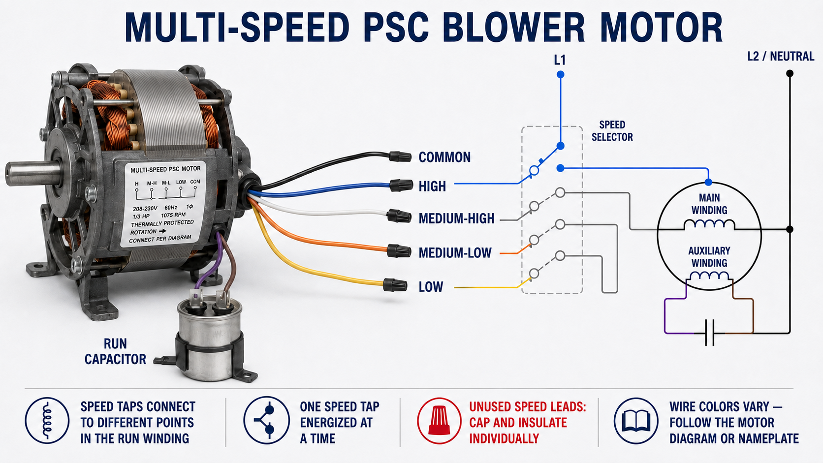
The illustrated wire colors are examples, not universal standards. A replacement motor may use different colors, a different number of speeds, a separate capacitor-common lead, or a different internal protector arrangement. Identify every lead from the label and diagram supplied with that motor.
| Lead or Connection | Typical Function | Service Requirement |
|---|---|---|
| Common | Completes the supply path shared by the selected speed circuit. | Connect exactly as shown; common may be associated with an internal protector. |
| High Speed | Selects the highest available nameplate speed. | Commonly used where the equipment requires its greatest designed airflow. |
| Intermediate Speeds | Select discrete speeds between high and low. | Used only when the equipment and motor data permit the selected airflow. |
| Low Speed | Selects the lowest available nameplate speed. | Must still provide the minimum airflow required for the active operating mode. |
| Capacitor Leads | Connect the run capacitor in the auxiliary-winding circuit. | Use the specified capacitance and voltage rating and follow the exact diagram. |
| Unused Speed Leads | Remain disconnected during the selected operating mode. | Cap and insulate each unused lead individually so it cannot contact another lead or ground. |
Do Not Tie Speed Taps Together
Only the speed tap selected for the operating mode should receive line voltage. Simultaneously energizing two speed taps can place voltage across an unintended section of the winding and cause circulating current, overheating, protective-device operation, or motor failure.
Equipment may use separate relay or control-board outputs for heating and cooling speeds. The control must prevent those outputs from energizing conflicting speed leads at the same time. Do not join speed leads merely because two operating modes are intended to use the same airflow; follow the equipment control diagram and use the approved isolation method.
Insulate Every Unused Lead Separately
Unused speed taps are connected to the motor winding and may develop voltage while another tap is energized. Do not twist unused speed leads together. Place an approved insulated connector on each lead individually and secure the leads away from moving parts and sharp edges.
The Correct Tap Is an Equipment Decision
Selecting a blower speed is not simply a matter of choosing the quietest setting. Airflow must satisfy the equipment manufacturer’s requirements for temperature rise, evaporator performance, heat-transfer rate, combustion-system limits, electric-heat airflow, refrigerant conditions, and condensate management.
Cooling
Insufficient airflow can lower evaporator temperature, contribute to icing, distort superheat and subcooling diagnosis, and reduce capacity. Excessive airflow may reduce dehumidification and create noise.
Gas Heating
Airflow must keep the furnace temperature rise within its rated range. Excessive temperature rise can operate limit controls and damage equipment.
Electric Heat
Approved airflow and interlocking are required so energized heating elements do not operate without adequate air movement.
Static Pressure
A speed designation does not guarantee a particular airflow. The blower wheel, duct system, filter, coil, dampers, and external static pressure affect delivered airflow.
Winding Sections Can Be Connected in Parallel or Series
A dual-voltage motor has winding sections designed to place the proper voltage across each section when the supply is connected correctly. For a common 2:1 voltage ratio, the sections are connected in parallel for the lower voltage and in series for the higher voltage.

| Connection | Winding Arrangement | Voltage Across Each Section |
|---|---|---|
| Lower Nameplate Voltage | Matching winding sections are connected in parallel. | Each section receives the full lower supply voltage for which it was designed. |
| Higher Nameplate Voltage | Matching winding sections are connected in series. | The higher supply voltage divides across the series sections so each receives its designed voltage. |
The nameplate voltage must match the measured supply and the lead arrangement. “Low voltage” and “high voltage” are relative to that motor’s dual rating; they do not identify control-voltage versus line-voltage circuits.
The Same Windings Cannot Use Either Supply Without Reconnection
| Error | Electrical Result | Likely Consequence |
|---|---|---|
| Parallel low-voltage connection placed on the higher supply | Each winding section receives excessive voltage. | Very high current, rapid overheating, protective-device operation, and possible winding failure. |
| Series high-voltage connection placed on the lower supply | Each winding section receives less than its intended voltage. | Reduced torque, slow acceleration, overheating, failure to start the load, or overload operation. |
| Incorrect series junction or lead pairing | Winding magnetic polarities may oppose or an unintended circuit may be created. | Failure to start, abnormal current, noise, overheating, or damage. |
| Supply does not match either nameplate rating | The motor operates outside its designed voltage. | Performance and life are not assured even if the motor appears to run. |
Reverse One Winding Relative to the Other
The direction of a reversible split-phase or capacitor motor depends on the magnetic relationship between its main winding and auxiliary winding. Reversing the two auxiliary-winding leads while leaving the main-winding connections unchanged reverses that relationship and reverses rotation. Reversing both windings preserves their relative relationship, so the direction does not change.
Some motors bring out the necessary leads and provide a reversal diagram; others are internally connected and are not field reversible. A direction arrow on a replacement motor, a shaft-end or lead-end viewing reference, and the equipment’s required wheel or fan rotation must all be interpreted correctly.
Reversible Single-Phase Motor
Follow the nameplate instructions to interchange the specified start or auxiliary leads relative to the run winding.
Nonreversible Single-Phase Motor
Do not open the motor or invent a lead change. Replace it with a motor having the required rotation and application rating.
Three-Phase Motor
For a conventional three-phase motor, rotation is normally reversed by interchanging any two supply phases after power is disconnected and the system diagram is verified.
Electronically Controlled Motor
ECM and inverter-driven motor direction may be programmed or controlled electronically. Use the manufacturer’s procedure rather than applying PSC rules.
A Motor Can Run Normally and Still Turn the Load Incorrectly
Verify the required rotation from the equipment and motor information before coupling the motor to the load. Rotation descriptions such as clockwise and counterclockwise are meaningless unless the viewing end is specified. Manufacturers may state rotation as viewed from the shaft end, lead end, or opposite shaft end.
A centrifugal blower wheel installed or rotated incorrectly may still move some air, but its airflow and efficiency can be severely reduced. Propeller fans, condenser fans, pumps, and compressors also depend on the correct mechanical and electrical direction. Never use airflow direction alone as the only rotation check.
- Find the motor’s stated viewing reference and rotation arrow.
- Find the equipment’s required wheel, fan, pump, or compressor rotation.
- Confirm the motor is mechanically appropriate for the load.
- Perform a guarded momentary test only after the correct connection and safe test procedure are established.
- Verify current, airflow or load performance, vibration, and full-speed operation.
Use a Deliberate Connection Process
Read the Nameplate
Confirm horsepower, voltage, phase, frequency, current, speed, rotation, capacitor, duty, enclosure, frame, and application ratings.
Measure the Supply
Verify the available voltage and phase with properly rated instruments before selecting a connection diagram.
Match the Exact Diagram
Select the connection for the measured supply and required rotation from the motor’s own label or manufacturer documentation.
Identify Every Lead
Trace lead markings rather than relying on color, especially when adapters, repairs, or replacement motors are involved.
Make and Protect Connections
Use approved connectors, correct torque, grounding, strain relief, individual insulation, and routing away from moving or hot parts.
Inspect Before Energizing
Compare each completed junction with the diagram, replace covers and guards, clear the area, and follow the approved startup procedure.
A Correct Connection Does Not Make an Incorrect Motor Suitable
A replacement motor must match more than voltage and horsepower. Verify phase, frequency, full-load current, speed choices, rotation or reversibility, shaft dimensions, frame and mounting, enclosure, bearing orientation, ambient rating, service factor, thermal protection, capacitor requirements, and suitability for the specific fan, blower, pump, or refrigeration application.
For a PSC replacement, use the capacitor value specified for the replacement motor, not automatically the capacitor used by the original motor. A dual-rated capacitor may serve more than one component, but each section must have the capacitance and voltage rating required by the connected load.
Do Not Defeat Equipment Safeties
Do not bypass door switches, fan interlocks, overload protection, limits, pressure controls, or control-board logic to make a replacement motor operate. Resolve incompatibilities with the correct motor, approved accessory, or manufacturer procedure.
Avoid These Connection Mistakes
Trusting Wire Color
Color conventions vary among manufacturers and replacement motors. Trace markings and use the exact diagram.
Energizing Two Speed Leads
Two energized taps can create destructive winding currents. The control must select only the intended tap.
Bundling Unused Taps
Unused speed leads must be insulated individually because they remain connected to winding points.
Confusing Voltage Ratings
Reconnect the windings for the actual supply. The nameplate slash rating does not mean either voltage can be applied to one unchanged connection.
Reversing Both Windings
Reversing both windings does not change their relationship and therefore does not reverse the motor.
Ignoring Viewing Direction
Clockwise from the shaft end is counterclockwise from the opposite end. Confirm the manufacturer’s reference.
Review Questions
1. How many speed taps should normally be energized at one time on the illustrated PSC blower motor?
One—the tap selected for the active operating mode.
2. How should unused speed leads be handled?
Cap and insulate each unused lead individually and secure it away from moving parts, sharp edges, and grounded metal.
3. Why is the lowest blower speed not automatically the best choice?
The selected speed must deliver airflow within the equipment requirements for cooling, heating, temperature rise, pressure, safety, and performance.
4. How are matching winding sections commonly connected for the lower voltage of a 2:1 dual-voltage motor?
In parallel so each section receives the full lower supply voltage.
5. How are those winding sections connected for the higher voltage?
In series so the higher supply voltage divides across the two sections.
6. What is changed to reverse an applicable single-phase motor?
The auxiliary or start winding is reversed relative to the main or run winding according to the motor diagram.
7. Why does reversing both single-phase windings not reverse the motor?
The magnetic relationship between the two windings remains the same.
8. What is the normal way to reverse a conventional three-phase motor?
After de-energizing and verifying the approved procedure, interchange any two supply phases.
Key Takeaways
- Multi-speed PSC motors use winding taps to provide discrete operating speeds.
- Only the intended speed tap is energized, and every unused tap is insulated individually.
- Blower speed must satisfy equipment airflow requirements rather than merely reduce noise.
- For common 2:1 dual-voltage windings, the lower voltage uses parallel sections and the higher voltage uses series sections.
- An applicable single-phase motor is reversed by reversing one winding relative to the other, normally the auxiliary winding.
- Not every single-phase motor is field reversible, and rotation descriptions require a stated viewing direction.
- Wire colors and generic lead labels are not universal; the specific nameplate and manufacturer connection diagram control the work.