Electronically Commutated Motors
An electronically commutated motor, commonly called an ECM, combines a permanent-magnet motor with an electronic control module. The module converts the incoming AC supply to DC and electronically switches current through the stator windings in the sequence needed to produce rotation.
ECMs can provide higher efficiency, soft starting, multiple programmed outputs, and better control of blower performance than traditional PSC motors. Those benefits also change the service procedure: the technician must evaluate line-voltage power, low-voltage or communicating commands, connectors, programming, motor windings, and the electronic module as parts of one system.
Learning Objectives
Explain ECM Construction
Identify the permanent-magnet rotor, stator windings, rectifier, DC bus, inverter, and electronic controls.
Follow Power Flow
Trace energy from the AC supply through rectification and electronic switching to the motor stator.
Distinguish Control Methods
Compare selectable-input, constant-torque, constant-airflow, and communicating ECM applications.
Use a Safe Diagnostic Process
Separate missing power, missing control commands, connection problems, mechanical load faults, programming errors, and motor-module failures.
Electronic Commutation Replaces the PSC Phase-Shifting Circuit
A PSC motor uses AC line power, a main winding, an auxiliary winding, and an external run capacitor to create the magnetic conditions needed for operation. A typical HVAC ECM instead uses electronic switches to energize multiple stator winding phases in sequence. Its permanent-magnet rotor follows the rotating magnetic field produced by the controlled stator currents.
Because commutation is electronic, the module can control speed and torque without traditional speed taps in the PSC sense. Some ECMs accept discrete input calls that resemble speed selections, while others receive a digital command and continuously adjust operation. The external wiring and control behavior depend on the particular motor and equipment design.
| Feature | Traditional PSC Motor | Typical ECM |
|---|---|---|
| Rotor | Induction squirrel-cage rotor | Permanent-magnet rotor |
| Commutation or Phase Control | AC winding design and capacitor create the phase relationship | Electronic switches sequence current through the stator |
| External Run Capacitor | Normally required | Not used as a PSC run capacitor |
| Speed or Output Selection | Often separate line-voltage winding taps | May use low-voltage inputs, line-voltage inputs, programming, or digital communication |
| Operating Response | Speed changes with motor design, voltage, and load | Module may regulate torque, speed, or airflow according to its programming |
The Motor and Electronic Module Work Together
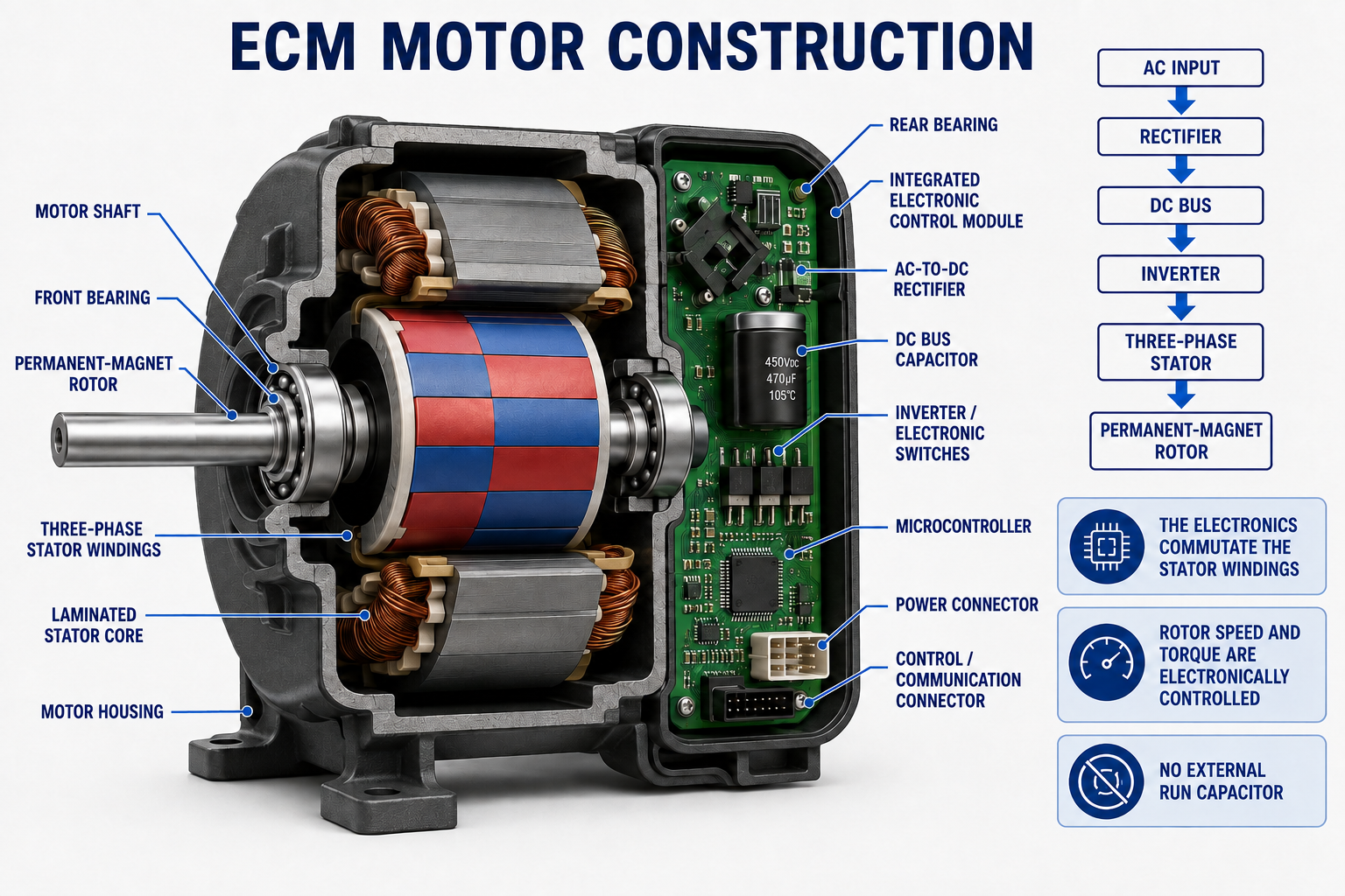
| Component | Function | Service Significance |
|---|---|---|
| Permanent-Magnet Rotor | Follows the rotating stator field and transfers torque to the shaft. | Magnets eliminate rotor current losses but can generate voltage when the rotor is driven. |
| Multi-Phase Stator | Produces the rotating magnetic field when phases are electronically energized. | Winding tests require the motor manufacturer’s procedure and complete isolation from electronics. |
| Rectifier | Converts the incoming AC supply to DC. | A module may have line voltage present even when the motor has no run command. |
| DC Bus Capacitor | Filters and stores energy on the internal DC bus. | Hazardous voltage may remain after line power is removed; observe the specified discharge time. |
| Inverter Switches | Switch DC to the stator phases in the required sequence. | These power semiconductors can fail and are not tested like mechanical contacts. |
| Microcontroller | Interprets commands and controls commutation, acceleration, torque, speed, and protection. | Correct power without a valid command may correctly result in no operation. |
| Power Connector | Receives line-voltage power and equipment grounding connections. | Voltage, connector condition, pin fit, and ground integrity must be verified safely. |
| Control Connector | Receives discrete or communicating commands from the equipment. | Pinout, signal type, reference common, and test method vary by system. |
AC Input Becomes Controlled Multi-Phase Output
AC Input
The equipment supplies the nameplate line voltage to the motor’s power connector.
Rectification
Diodes or an electronic rectifier convert the alternating input into a direct-current supply.
DC Bus
A capacitor filters the rectified voltage and stores energy for the inverter stage.
Inversion
Power switches apply controlled pulses to the stator phases in an electronically timed sequence.
Rotating Field
The sequenced stator currents produce a rotating magnetic field.
Rotor Response
The permanent-magnet rotor follows the field, while the module adjusts operation to its command and programmed strategy.
Line Power and the Run Command Are Separate
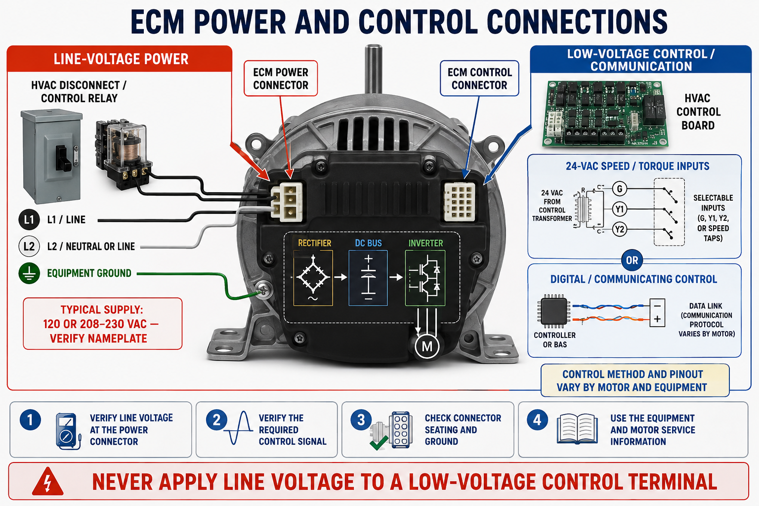
Many furnace and air-handler ECMs receive line power whenever the equipment is energized, while the control connector tells the module when and how to operate. Finding correct line voltage at the motor therefore does not prove that a valid control command is present. Likewise, finding a control call does not prove that line power and ground are correct.
Never Apply Line Voltage to a Low-Voltage Control Terminal
A control pin intended for 24 VAC, a low-voltage analog signal, or digital communication can be destroyed by line voltage. Identify the connector and pins from the exact equipment and motor service information before testing or applying any signal.
“ECM” Does Not Describe One Universal Control Method
Constant-Torque ECM
Selectable inputs call for programmed torque levels. Actual airflow changes as external static pressure and blower-system resistance change.
Constant-Airflow ECM
The motor and equipment programming attempt to maintain selected airflow over an approved static-pressure range by changing speed and torque.
Constant-Speed ECM
The control attempts to regulate motor speed at a programmed value, but delivered airflow still depends on the blower and system resistance.
Communicating ECM
A control board sends commands over a manufacturer-specific data link and may receive operating or fault information from the motor.
Line-Voltage-Selected ECM
Some aftermarket or application-specific ECMs accept switched line-voltage inputs in a way that resembles a PSC replacement connection.
Programmed Replacement ECM
A universal or service motor may require configuration for horsepower, rotation, airflow, torque, speed, or an OEM performance profile before use.
Terms used in product literature are not always interchangeable. “Variable speed” often describes a constant-airflow communicating blower, while “multi-speed” may describe several selectable programmed outputs. Determine what the specific motor actually controls rather than relying on the marketing label.
An ECM Cannot Correct Every Airflow Problem
A constant-airflow ECM can increase speed and torque as external static pressure rises, but only within its programmed and mechanical operating range. A dirty filter, restricted coil, closed damper, undersized duct, blocked return, or incorrect blower wheel can cause the motor to work harder, consume more power, create noise, or reach its control limit.
A constant-torque ECM responds differently: it attempts to maintain its programmed torque, so airflow usually falls as system resistance increases. Technicians must know the control strategy before interpreting motor speed, current, wattage, sound, or airflow.
| System Change | Constant-Torque Response | Constant-Airflow Response |
|---|---|---|
| External static pressure increases | Airflow generally decreases. | Motor may increase speed and power to maintain programmed airflow within its range. |
| External static pressure decreases | Airflow generally increases. | Motor may reduce speed and power while maintaining programmed airflow. |
| Restriction exceeds motor or equipment range | Required airflow may not be delivered. | Programmed airflow may not be maintained, and noise or power can become excessive. |
Stored Energy and Permanent Magnets Add Hazards
Removing the Run Command Does Not Remove Line Voltage
De-energize the equipment disconnect, apply required lockout/tagout procedures, verify all power legs are open, and wait the manufacturer-specified discharge time before disconnecting or opening an ECM module. Internal DC-bus capacitors may retain hazardous energy after power is removed.
A permanent-magnet motor can generate voltage if its shaft or blower wheel is driven by hand, airflow, or another mechanical source. Prevent unintended rotation during service and use the manufacturer’s connector-removal sequence. Never insert meter probes in a way that spreads, bends, or shorts connector terminals.
Do not apply a megohmmeter or high-potential test through an ECM module or connected control board. Insulation testing, winding testing, and module separation must follow the motor manufacturer’s procedure because an improper test voltage can destroy electronics.
Verify Inputs Before Condemning the Motor
Identify the Motor
Record the complete motor, module, and equipment model information and obtain the correct wiring and service procedure.
Inspect the System
Check the blower wheel or load, mounting, connectors, harnesses, grounds, moisture evidence, overheating, airflow restrictions, and mechanical freedom.
Verify Line Power
Use the specified reference points to confirm the correct line voltage at the power connector under the required operating condition.
Verify the Command
Confirm the correct discrete input, 24-VAC call, analog signal, or communication activity using the approved test method.
Use Built-In Diagnostics
Read equipment and motor fault codes, service-tool data, and control-board status without assuming that a code identifies the failed part.
Test as Directed
Perform manufacturer-approved motor, module, harness, and load tests and compare the results with the specified limits.
One Symptom Can Have Several Causes
| Symptom | Possible Causes to Separate |
|---|---|
| Motor does not run | Missing line power, missing control command, open harness, connector damage, equipment lockout, failed module, failed motor, or mechanically blocked load. |
| Motor runs at the wrong output | Wrong input call, incorrect programming, misplaced connector, control-board logic, wrong replacement motor, or incorrect equipment setup. |
| Motor surges or repeatedly starts | Intermittent power or command, excessive static pressure, unstable communication, loose connection, module protection, or mechanical load problem. |
| Airflow is low | Dirty filter or coil, restricted duct, incorrect airflow selection, wrong blower wheel or rotation, constant-torque response, or motor limitation. |
| Motor is unusually loud or fast | High static pressure, constant-airflow compensation, wrong programming, wheel damage, loose mounting, or incorrect motor application. |
| Module fails again | Supply disturbance, poor grounding, moisture, overheating, incorrect replacement, damaged harness, load problem, or unresolved equipment fault. |
Use the Correct Reference and Protect the Pins
Control signals must be measured between the reference points specified by the manufacturer. A voltage measured to chassis ground may not represent the signal seen by the module. Communicating conductors cannot be evaluated reliably by assuming they are ordinary thermostat inputs.
Back-probe only when the approved procedure and test adapters permit it. Oversized probes can spread connector contacts and create an intermittent failure after the test. Inspect for pin pushout, corrosion, moisture, damaged locks, overheated terminals, poor crimping, and harness tension.
ECM Windings Are Not Tested Like PSC Speed Taps
When the manufacturer permits separation of the motor and module, the isolated stator phases may be checked for balanced resistance and for insulation to the frame using the specified instruments and procedure. Very low resistance and module connections can make ordinary field readings misleading.
Never apply line voltage directly to exposed stator leads to “see if the motor runs.” The stator requires electronically sequenced power from the correct module. Likewise, spinning the shaft and interpreting generated voltage is valid only when it is part of a manufacturer-approved test with stated limits.
Some products allow separate module replacement, some require motor-and-module replacement as a matched assembly, and some replacements must be programmed before operation. Preserve parameter data when required and verify that replacement programming matches the equipment, horsepower, rotation, blower, and airflow table.
Mechanical Fit Is Only the Beginning
| Requirement | Why It Matters |
|---|---|
| Approved Cross-Reference | Confirms that the replacement is intended for the equipment and control method. |
| Voltage and Horsepower | Must match the supply and load without exceeding equipment ratings. |
| Control Interface | Discrete 24-VAC, line-voltage, analog, and communicating controls are not interchangeable. |
| Programming | Torque, airflow, speed, ramping, delays, and rotation may be stored in the motor or module. |
| Rotation | May be fixed, harness-selected, programmed, or automatically determined depending on the motor. |
| Frame, Shaft, and Mounting | Incorrect geometry can damage the wheel, create vibration, or place the module in an unapproved orientation. |
| Environment and Cooling | The motor and module must be suitable for moisture, temperature, airflow-over-motor, and enclosure conditions. |
| Final Airflow Setup | DIP switches, menus, taps, or programming must match the equipment airflow tables after installation. |
Avoid These ECM Diagnostic Mistakes
Assuming Power Means Run
Many ECMs have line voltage continuously and wait for a separate valid command.
Applying the Wrong Test Signal
Line voltage on a low-voltage or data terminal can instantly destroy the module.
Ignoring Static Pressure
A fast or noisy constant-airflow motor may be correctly responding to a restricted system.
Testing Through Electronics
Resistance or insulation tests through the module can give false results or damage components.
Replacing Without Programming
A physically compatible ECM can deliver the wrong airflow or rotation if its profile is not configured.
Forcing Connector Pins
Improper probes and mismatched plugs can create loose contacts and intermittent faults.
Review Questions
1. What does the rectifier in an ECM do?
It converts the incoming AC supply to DC for the internal DC bus and inverter.
2. What creates the rotating magnetic field in an ECM?
The electronic module switches current through the stator phases in a controlled sequence.
3. Does a typical ECM require an external PSC run capacitor?
No. Its electronic commutation does not use an external run capacitor as a PSC motor does.
4. Why might correct line voltage be present while the motor is stopped?
The module may be powered but waiting for a valid low-voltage or communicating run command.
5. How does a constant-airflow ECM commonly respond to increasing static pressure?
Within its programmed range, it may increase speed and torque in an attempt to maintain airflow.
6. Why can the DC bus remain hazardous after power is disconnected?
Its capacitors store electrical energy and require the specified time and procedure to discharge.
7. Why should line voltage never be applied to an unidentified control pin?
The pin may be intended for 24 VAC, another low-voltage signal, or digital communication, and line voltage can destroy the electronics.
8. What should be verified before an ECM is condemned?
Verify the correct line power, ground, run command, connectors, configuration, mechanical load, airflow system, diagnostic information, and manufacturer-directed tests.
Key Takeaways
- An ECM combines a permanent-magnet motor with a rectifier, DC bus, inverter, and electronic control.
- The module creates a controlled multi-phase stator field even when supplied by single-phase AC.
- Line-voltage power and the control command are separate diagnostic requirements.
- ECMs may regulate torque, airflow, or speed, or respond to a manufacturer-specific communication protocol.
- A fast or noisy ECM can be responding to excessive external static pressure rather than failing.
- DC-bus capacitors may retain hazardous voltage, and a permanent-magnet rotor can generate voltage when driven.
- Never apply line voltage to an unidentified control terminal or use high-voltage insulation tests through electronics.
- Replacement ECMs must match the control interface and may require equipment-specific programming.