Three-Phase Power and Motor Operation
Three-phase power uses three alternating voltage waveforms of the same frequency that are displaced from one another by 120 electrical degrees. When applied to stator windings arranged around a motor, the three currents produce a magnetic field that rotates continuously without the auxiliary starting circuit required by a conventional single-phase induction motor.
Three-phase motors are widely used in commercial and industrial HVAC/R compressors, pumps, fans, cooling towers, air handlers, and refrigeration equipment. Understanding phase sequence, line and phase quantities, and wye and delta connections prepares technicians to install and diagnose these systems safely.
Learning Objectives
Describe Three-Phase Power
Explain the relationship among three equal AC phases separated by 120 electrical degrees.
Explain the Rotating Field
Describe how the three stator currents combine to produce a continuously rotating magnetic field.
Distinguish Line and Phase Values
Apply the balanced-system voltage and current relationships for wye and delta connections.
Recognize Service Implications
Relate phase sequence, voltage balance, loss of a phase, motor connections, and equipment documentation to safe HVAC/R service.
Three-Phase Equipment Can Have Significant Fault Energy
De-Energize Before Opening or Changing Connections
Identify every source, follow the required lockout/tagout procedure, open all ungrounded conductors, verify absence of voltage with properly rated test equipment, and discharge stored electrical energy before servicing. Conductors that have been switched off but not properly locked or tagged must be treated as energized under applicable safety procedures.
Only qualified persons using the required work practices, PPE, insulated tools, and test instruments may perform measurements on exposed energized parts. Determine the available voltage, equipment category, fault-current and arc-flash hazards, and site procedures before testing. A control switch, contactor, thermostat, or VFD stop command is not an energy-isolating device.
Each Phase Reaches Its Peak at a Different Time
In a balanced sinusoidal three-phase set, phases A, B, and C have equal magnitude and frequency but are separated by 120 electrical degrees. When one phase is at a particular point in its cycle, the other two phases are at different instantaneous values. This orderly displacement is what makes three-phase power fundamentally different from three identical conductors carrying the same waveform.
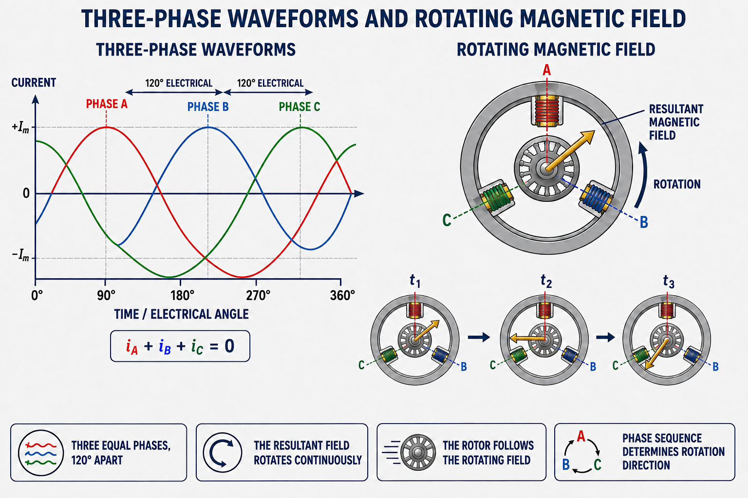
For a balanced three-wire load, the instantaneous phase currents add algebraically to zero. The corresponding phasor sum is also zero. When the source or load becomes unbalanced, the currents are no longer equal, and those balanced-system relationships cannot be applied without accounting for the actual circuit.
120 Electrical Degrees Does Not Mean 120 Degrees of Shaft Rotation
Electrical degrees describe position within an AC cycle. Mechanical degrees describe physical shaft position. Their relationship depends on the number of motor poles. A two-pole field completes one electrical cycle per mechanical revolution, while a four-pole field completes two electrical cycles per mechanical revolution.
The supply frequency and number of poles determine synchronous field speed:
| Poles | Synchronous Speed at 60 Hz | Typical Induction-Motor Nameplate Speed |
|---|---|---|
| 2 | 3,600 RPM | Approximately 3,450 RPM |
| 4 | 1,800 RPM | Approximately 1,725 RPM |
| 6 | 1,200 RPM | Approximately 1,140 RPM |
| 8 | 900 RPM | Approximately 850 RPM |
The exact loaded speed depends on motor design and load. A conventional induction motor must operate below synchronous speed to induce rotor current and develop torque; that difference is called slip.
The Three Stator Fields Combine Continuously
Phase Currents Flow
Three currents displaced in time flow through stator windings displaced in space around the motor.
Each Phase Creates a Field
The magnitude and polarity of each winding’s magnetic field follow its instantaneous current.
Fields Add Vectorially
The three changing fields combine into one resultant magnetic field.
The Resultant Rotates
As the phase currents progress through their cycles, the resultant field moves smoothly around the stator.
Rotor Torque Develops
In an induction motor, the moving field induces rotor current whose magnetic interaction produces torque.
The Rotor Follows
The rotor accelerates in the direction of the field and settles below synchronous speed under load.
This naturally rotating field is why a standard three-phase induction motor does not need a centrifugal switch, start capacitor, or separate start winding. Large motors may still require reduced-current or electronically controlled starting methods to limit inrush and mechanical stress.
The Order of the Phases Determines Rotation
Phase sequence is the order in which the three phase waveforms reach corresponding points in their cycles. A sequence of A-B-C produces one field direction; exchanging any two supply phases changes the sequence to the opposite order and reverses the rotating field.
Do not assume that L1-L2-L3 labels at a replacement disconnect, starter, VFD, or motor produce the required mechanical rotation. Verify the equipment’s required direction and use an approved phase-sequence instrument or guarded bump test as permitted. Pumps, scroll compressors, screw compressors, fans, and other directional loads can be damaged or perform incorrectly if operated backward.
VFD Input and Output Leads Are Different
For a VFD-controlled motor, follow the drive manufacturer and equipment instructions. Do not move conductors on an energized drive, and do not install switching devices or interchange motor leads between the drive and motor unless the system is designed and controlled for that operation. Stored DC-bus voltage can remain after input power is removed.
Three-Phase Power Suits Larger HVAC/R Loads
Self-Starting Field
The rotating stator field develops starting torque without a single-phase start-winding circuit.
Smoother Torque
Balanced phase contributions provide more uniform power transfer and torque than comparable single-phase operation.
Efficient Power Delivery
Three-phase systems efficiently supply large motors and other commercial or industrial loads.
Simpler Motor Construction
A squirrel-cage three-phase induction motor can be rugged and relatively simple because it needs no brushes or starting switch.
Easy Direction Change
Interchanging any two phases reverses a conventional three-phase motor when the approved procedure is followed.
VFD Compatibility
Suitable three-phase motors can be operated by variable-frequency drives for controlled speed, torque, and system capacity.
The Windings Can Form a Star or a Closed Triangle
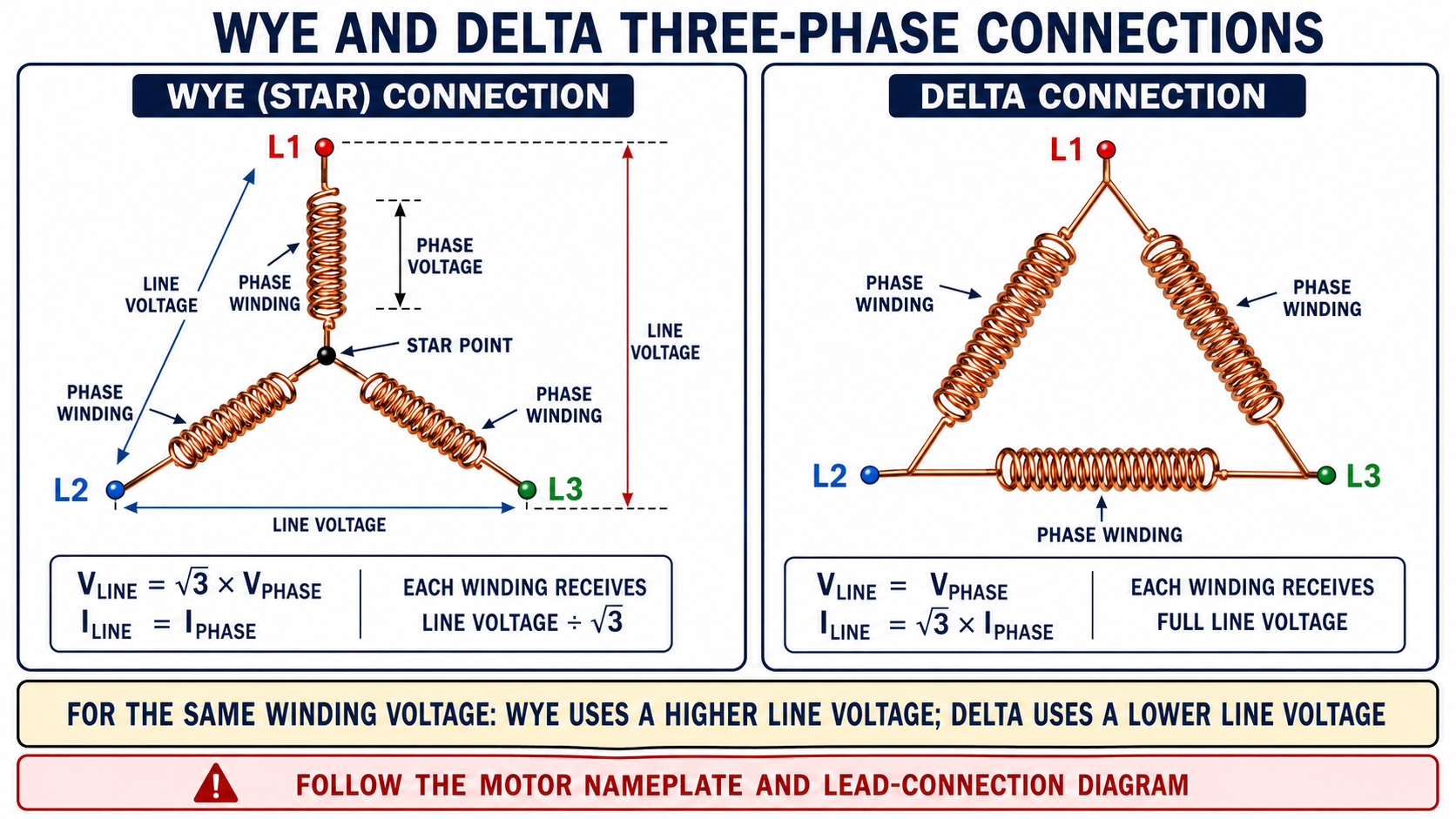
Three motor or load windings can be connected in wye, also called star, or in delta. In a wye connection, one end of each phase joins at a common star point and the remaining ends connect to the three lines. In delta, the windings connect end-to-end in a closed loop, and each junction connects to a line.
| Balanced Connection | Voltage Relationship | Current Relationship | Winding Voltage |
|---|---|---|---|
| Wye (Y) | Vline = √3 × Vphase | Iline = Iphase | Vphase = Vline ÷ √3 |
| Delta (Δ) | Vline = Vphase | Iline = √3 × Iphase | Each phase receives full line voltage |
Line Voltage and Winding Voltage Are Not Always the Same
The square root of three is approximately 1.732. If a balanced wye-connected winding operates from 480 V line-to-line, the voltage across each phase winding is approximately 277 V:
In a balanced delta-connected motor supplied with 240 V line-to-line, each phase winding receives 240 V. For the same designed winding voltage, a wye connection therefore uses a line voltage √3 times the delta line voltage. This principle explains some dual-voltage motor connections, but actual lead groupings must always come from the nameplate diagram.
Do Not Reconnect a Motor From the Figure Alone
The simplified figure does not identify a specific six-, nine-, or twelve-lead motor. Lead numbering, internal junctions, voltage ratios, wye/delta starting, part-winding starting, and VFD requirements vary. Follow the exact motor and equipment connection diagrams.
These Terms Describe Different Conductors and Quantities
| Term | Meaning | Important Distinction |
|---|---|---|
| Line Conductor | One of the conductors carrying power from the three-phase source to the load. | L1, L2, and L3 are normally ungrounded conductors. |
| Phase Winding | One winding or impedance branch within a wye or delta load. | Phase voltage and current may differ from measured line quantities. |
| Neutral | A grounded circuit conductor connected to the source or load neutral point when the system provides one. | Many three-phase motors use only L1, L2, L3, and equipment ground; they do not use a neutral. |
| Equipment Ground | A safety path bonding non-current-carrying metal parts to the grounding system. | It is not a normal load-current conductor and must never substitute for neutral. |
| Star Point | The common junction of three wye-connected phase windings. | It may be internal and inaccessible and is not automatically a usable neutral terminal. |
Balanced Power Depends on Voltage, Current, and Power Factor
For a balanced three-phase load, apparent power and real power can be calculated from line quantities:
Apparent power S is measured in volt-amperes, while real power P is measured in watts. Power factor accounts for the phase relationship and waveform effects between voltage and current. Motor efficiency is a separate relationship between electrical input power and mechanical output power.
Do not use these balanced formulas to diagnose an operating motor until all line voltages and currents have been measured and the system’s waveform and drive conditions are understood. VFD outputs may require instruments and procedures specified by the drive manufacturer.
All Three Lines Must Be Evaluated
A healthy three-phase motor circuit requires the correct voltage on all three lines, sound connections, appropriate protection, and balanced motor windings and load conditions. Voltage unbalance can produce much greater current unbalance and overheating. A blown fuse, open contactor pole, loose terminal, failed conductor, or open winding can remove one phase.
Loss of one phase is commonly called single-phasing. A stopped motor may fail to start and draw high current on the remaining lines. A running motor may continue with reduced torque, excessive current, overheating, vibration, or abnormal sound. Promptly de-energize the equipment and identify the cause rather than repeatedly resetting protection.
| Check | Measurements or Inspection | Purpose |
|---|---|---|
| Supply Voltage | L1-L2, L2-L3, and L1-L3 at appropriate points under the specified condition | Detect missing or unbalanced line voltage and voltage drop. |
| Operating Current | Current in L1, L2, and L3 with suitable instruments | Identify current imbalance, overload, or loss of a current path. |
| De-Energized Circuit | Fuses, contactor poles, terminals, conductors, and winding resistance | Locate opens, high-resistance connections, or winding imbalance. |
| Mechanical and System Load | Bearings, fan or pump, compressor condition, pressure, airflow, alignment, and driven load | Separate an electrical imbalance from an overloaded or damaged machine. |
Avoid These Three-Phase Errors
“Three Phase Means Three Voltages”
The phases have equal nominal magnitude and frequency but different time positions; they are one coordinated system.
“Every Wye Motor Uses Neutral”
A balanced three-phase motor normally operates from three line conductors without a neutral connection.
“Ground Can Replace Neutral”
Equipment ground is a protective path, not a normal current-carrying substitute for a grounded conductor.
“Line Voltage Equals Winding Voltage”
That is true for balanced delta, but a balanced wye phase receives line voltage divided by √3.
“Any Motor Can Be Changed Wye to Delta”
Only motors designed and labeled for the intended reconnection may be changed.
“One Voltage Reading Is Enough”
All three line-to-line combinations must be evaluated to identify missing or unbalanced phases.
Review Questions
1. How far apart are the phases in a balanced three-phase system?
They are separated by 120 electrical degrees.
2. Why does a standard three-phase induction motor not need a start winding?
The three displaced stator currents naturally create a rotating magnetic field with starting torque.
3. What determines synchronous speed?
Supply frequency and the number of stator poles determine synchronous speed.
4. What determines the direction of the rotating field?
The phase sequence determines field direction; interchanging any two phases reverses the sequence.
5. In a balanced wye connection, how does line voltage compare with phase voltage?
Line voltage equals √3 times phase voltage, so phase voltage equals line voltage divided by √3.
6. In a balanced delta connection, how does phase voltage compare with line voltage?
Phase voltage equals line voltage.
7. Does a wye-connected three-phase motor necessarily require a neutral conductor?
No. A balanced three-phase motor commonly uses three line conductors and equipment ground without neutral.
8. What is single-phasing?
Single-phasing is the loss of one phase in a three-phase motor circuit, which can prevent starting or cause excessive current, low torque, and overheating.
Key Takeaways
- Balanced three-phase waveforms have equal frequency and magnitude and are separated by 120 electrical degrees.
- Three spatially arranged stator windings create a continuously rotating resultant magnetic field.
- Phase sequence determines rotation direction.
- Wye joins three phase windings at a star point; delta connects them in a closed loop.
- For balanced wye, Vline = √3Vphase and Iline = Iphase.
- For balanced delta, Vline = Vphase and Iline = √3Iphase.
- A three-phase motor normally does not require a neutral, but it always requires the specified equipment grounding connection.
- All three line voltages and currents must be evaluated when diagnosing balance or single-phasing.