Three-Phase Induction Motors and Rotation
A three-phase squirrel-cage induction motor converts the rotating magnetic field of the stator into shaft torque without brushes, a commutator, a start capacitor, or a centrifugal switch. Current is induced in the rotor conductors, and the interaction between the rotor field and stator field pulls the rotor in the direction of field rotation.
These motors are durable and widely used on commercial HVAC/R compressors, pumps, fans, blowers, and cooling towers. Correct application still requires attention to nameplate ratings, load, starting method, phase balance, cooling, alignment, bearing condition, phase sequence, and the required rotation of the driven equipment.
Learning Objectives
Identify Motor Components
Describe the stator, squirrel-cage rotor, shaft, bearings, air gap, frame, cooling system, and terminal box.
Explain Induction and Torque
Trace the operating sequence from stator current to rotating field, induced rotor current, and shaft torque.
Relate Slip to Load
Explain why the rotor runs below synchronous speed and why slip normally increases as load increases.
Verify and Change Rotation
Safely determine required rotation and explain how interchanging any two phases reverses a conventional three-phase motor.
De-Energize the Electrical and Mechanical System
A Stop Command Is Not Energy Isolation
Open the required disconnecting means, follow the applicable lockout/tagout procedure, verify absence of voltage on all phases, discharge stored electrical energy, and control mechanical, pressure, thermal, gravitational, and fluid-flow energy before service. A contactor, thermostat, VFD stop key, BAS command, or control switch does not provide energy isolation.
Rotating equipment can coast after power is removed, and fans or pumps can be driven by airflow or fluid flow. Prevent unexpected shaft movement before removing guards, opening couplings, testing bearings, or changing conductors. Only qualified persons may perform measurements on exposed energized components using the required PPE and work practices.
Stationary Windings Surround a Conductive Rotor
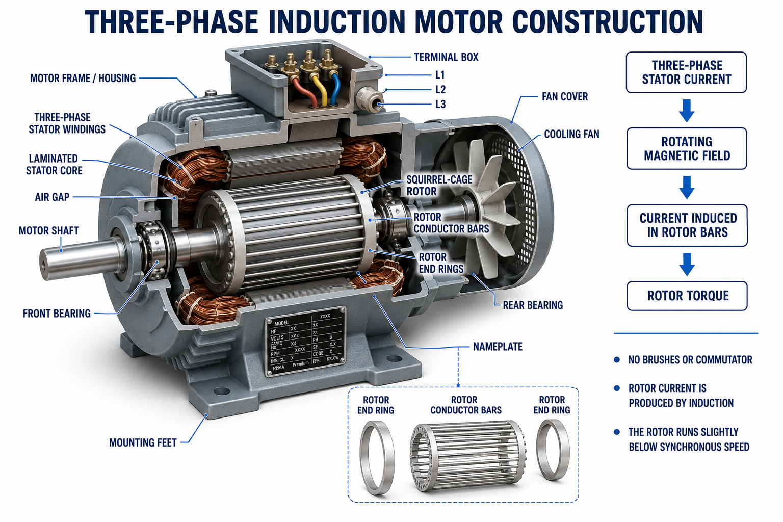
| Component | Function | Service Significance |
|---|---|---|
| Three-Phase Stator Windings | Create the rotating magnetic field. | Connections, winding balance, insulation, voltage, and cooling determine reliable operation. |
| Laminated Stator Core | Provides a magnetic path while laminations reduce eddy-current losses. | Core damage or stator-to-rotor contact can cause heat, current, vibration, and failure. |
| Squirrel-Cage Rotor | Contains conductive bars shorted together by end rings. | Broken bars or damaged end rings can cause low torque, vibration, current pulsation, and overheating. |
| Air Gap | Provides clearance between stator and rotor while allowing magnetic coupling. | Bearing wear, misalignment, or mechanical damage can make the air gap uneven and permit rubbing. |
| Shaft and Bearings | Support rotation and transmit torque to the driven load. | Lubrication, alignment, belt tension, thrust, contamination, and mounting affect bearing life. |
| Frame and Mounting | Support and protect the motor and transfer forces to the equipment. | Loose feet, soft foot, incorrect frame, or poor alignment can create vibration and bearing problems. |
| Cooling System | Moves heat away from windings, bearings, frame, and rotor. | Blocked passages, a damaged fan, wrong rotation, dirt, or inadequate airflow can overheat the motor. |
| Terminal Box and Nameplate | Provide protected connections and required application information. | Lead connections must match voltage, starting method, and manufacturer diagram. |
Rotor Current Is Induced by Relative Motion
Three-Phase Current Flows
The supply sends three phase currents through stator windings arranged around the motor.
The Stator Field Rotates
The displaced phase currents combine to create a magnetic field rotating at synchronous speed.
Flux Cuts Rotor Bars
Relative motion between the rotating field and rotor conductors induces voltage in the bars.
Rotor Current Flows
The bars and end rings form closed conductive paths, allowing induced current to circulate.
Rotor Field Develops
The induced currents create a rotor magnetic field that interacts with the stator field.
Torque Accelerates the Load
The interaction produces torque in the direction of the rotating stator field.
Rotor Speed Falls Slightly Below Field Speed
Slip is the difference between synchronous field speed and actual rotor speed, expressed as a percentage of synchronous speed:
A four-pole, 60-Hz motor has a synchronous speed of 1,800 RPM. If its measured loaded speed is 1,755 RPM, slip is 2.5%:
When mechanical load increases within the motor’s normal range, rotor speed decreases slightly. Greater relative motion induces more rotor current and develops more torque. If the load exceeds available torque, the motor can slow excessively or stall, producing high current and rapid heating.
| Operating Condition | Relative Slip | Typical Effect |
|---|---|---|
| No Load or Very Light Load | Low | Rotor speed is close to synchronous speed, though input current still includes magnetizing current. |
| Rated Load | Normal nameplate range | Motor delivers rated torque near its nameplate RPM. |
| Increasing Load | Increases | Speed drops slightly while rotor current and torque increase. |
| Stall or Locked Rotor | 100% | Rotor is stationary, current is very high, and cooling may be inadequate. |
Starting Current and Torque Must Match the Application
At standstill, slip is 100%, and an across-the-line induction motor can draw several times its rated running current. The actual locked-rotor current, starting torque, acceleration time, and allowable starts depend on the motor design and nameplate data, the supply system, starter, driven-load torque, and inertia.
Across-the-Line Starting
A contactor applies full line voltage to the motor. It is simple but can produce high electrical inrush and mechanical stress.
Reduced-Voltage Starting
Approved starters reduce voltage or change winding connection during acceleration, reducing current but also reducing available torque.
Soft Starter
Solid-state devices ramp applied voltage to control acceleration and starting current, then may transfer to a bypass contactor.
Variable-Frequency Drive
A VFD controls voltage and frequency to manage starting, speed, torque, and system capacity when the motor and application are suitable.
Repeated starting can overheat a motor even if every individual start appears normal. Follow the specified starts-per-hour, minimum off-time, acceleration-time, and load requirements.
Interchanging Any Two Phases Reverses the Field
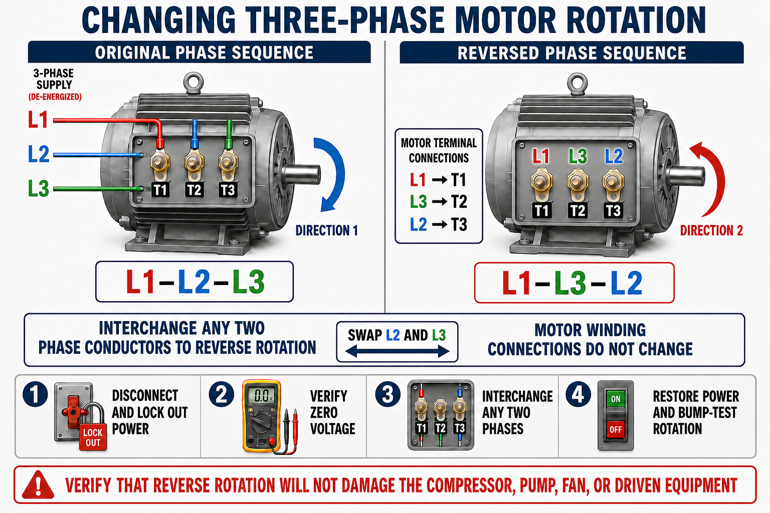
The figure exchanges L2 and L3, but any two phases could be exchanged. Swapping two phases twice returns to the original sequence. Changing all three conductors while preserving their order does not reverse rotation.
Confirm the Load Can Be Bump-Tested
Before momentarily energizing a motor, verify that reverse rotation, sudden motion, pressure change, loss of lubrication, fan or pump operation, compressor construction, valves, couplings, and connected controls will not injure personnel or damage equipment. Some compressors and pumps must never be operated backward, even briefly.
Plan the Test Before Applying Power
- Identify the required direction. Use equipment arrows, service literature, fan or pump information, and the stated viewing end.
- Determine whether a bump test is permitted. Consider the driven load, coupling, lubrication, process, pressure, automatic controls, and manufacturer restrictions.
- Inspect the installation. Verify mounting, alignment, guards, grounding, lead connections, control logic, and free mechanical movement.
- Clear personnel and tools. Restore required covers and guards and establish a safe observation point.
- Momentarily energize as approved. Observe the shaft or load only long enough to determine direction.
- If direction is wrong, de-energize fully. Lock out power, verify zero voltage on all phases, and control stored motion and energy.
- Interchange any two motor-supply phases at the approved point. Do not alter grounding, overload, or internal winding connections.
- Reinspect and retest. Restore enclosures and guards, then verify direction, current, vibration, load performance, and control operation.
Clockwise Requires a Reference Point
Clockwise and counterclockwise are incomplete unless the observer’s position is stated. Clockwise viewed from the shaft end appears counterclockwise viewed from the opposite end. Motor manufacturers may use terms such as shaft end, drive end, opposite shaft end, or lead end.
Verify both motor direction and driven-component direction. A centrifugal blower wheel, propeller fan, pump impeller, or compressor may move some air or fluid while rotating incorrectly, but capacity, lubrication, noise, pressure, and component life can be severely affected.
Follow the Drive Procedure, Not Only Line-Power Rules
A VFD rectifies its input and electronically creates a controlled three-phase output. Input phase sequence normally does not determine output rotation; drive programming and the order of output leads to the motor determine direction. Follow the drive and equipment instructions for forward and reverse commands.
Do not open the output circuit, interchange output leads, or place conventional contactors between a running drive and motor unless the system is specifically designed for that operation. Disconnect input power, wait the specified DC-bus discharge time, and verify the drive is safe before touching input or output terminals.
Do Not Megger Through a VFD
Isolate the motor and conductors from the drive before any manufacturer-approved insulation test. High test voltage applied through drive electronics can cause severe damage.
Electrical and Mechanical Conditions Work Together
| Check | What to Verify | Problem Prevented |
|---|---|---|
| Nameplate Match | Voltage, phase, frequency, horsepower, current, speed, duty, enclosure, ambient, service factor, efficiency, and VFD suitability | Overheating, insufficient torque, incorrect speed, or application failure |
| Lead Connection | Exact diagram for voltage and starting method; proper torque and insulation | Wrong winding voltage, open phase, high-resistance heating, or reversal |
| Supply | All line voltages, phase sequence, voltage balance, protection, and grounding | Single-phasing, current imbalance, shock, and premature insulation damage |
| Mounting and Alignment | Rigid base, soft foot, shaft alignment, coupling condition, pulley alignment, and belt tension | Vibration, bearing load, seal damage, and shaft failure |
| Cooling | Clean airflow path, correct fan, ambient temperature, altitude, and airflow-over-motor requirements | Excessive winding and bearing temperature |
| Driven Load | Free movement, correct rotation, valves or dampers, pressure, lubrication, and expected torque | Long acceleration, overload, stall, and equipment damage |
Current, Heat, Sound, and Vibration Need Context
| Observation | Possible Causes | Diagnostic Direction |
|---|---|---|
| Fails to start and hums | Missing phase, low voltage, incorrect connection, locked load, failed bearing, winding fault, or inadequate starting torque | De-energize promptly; check all phases, circuit continuity, connections, and mechanical load. |
| Starts slowly | Low voltage, excess inertia, overload, reduced-voltage starter problem, high friction, or wrong motor | Compare acceleration time, voltage under start, current, load, and starter sequence with specifications. |
| Unequal line currents | Voltage unbalance, high-resistance connection, winding imbalance, open circuit, or load-related issue | Measure all line-to-line voltages and currents at appropriate points and inspect de-energized connections. |
| Runs hot | Overload, imbalance, frequent starts, blocked cooling, high ambient, incorrect voltage, VFD settings, or winding damage | Check actual load, current, voltage, starts, cooling, drive data, and motor temperature limits. |
| Vibrates or sounds abnormal | Misalignment, soft foot, unbalance, bearing damage, rotor defect, rubbing, loose mounting, or driven-load problem | Separate motor, coupling, base, and load sources using approved mechanical and electrical tests. |
| Wrong rotation | Incorrect phase sequence or drive command | Verify required direction and use the approved de-energized reversal procedure. |
Avoid These Three-Phase Motor Mistakes
Changing Leads Energized
Phase conductors are changed only after full energy isolation and verification of zero voltage.
Assuming Direction
Phase labels do not guarantee the required shaft direction after installation or upstream electrical work.
Ignoring the Load
A motor that is electrically sound can overheat when the pump, compressor, fan, belt, or process is overloaded.
Calling Every Speed Drop a Fault
Some slip increase is necessary for an induction motor to produce additional torque as load increases.
Repeatedly Resetting Protection
An overload or breaker operation requires diagnosis; repeated restarting can intensify damage.
Treating a VFD Like a Contactor
Drive output, stored DC voltage, switching, testing, and rotation procedures require drive-specific instructions.
Review Questions
1. Why is the rotor called a squirrel cage?
Conductive rotor bars are shorted together by end rings, forming a structure resembling a cage.
2. How does current reach the rotor bars?
It is induced by relative motion between the rotating stator field and the rotor conductors.
3. Why must an induction rotor run below synchronous speed?
Relative motion is required to induce rotor voltage and current and therefore produce torque.
4. What normally happens to slip as mechanical load increases?
Slip increases as rotor speed decreases slightly and the motor develops more torque.
5. What is slip when the rotor is locked?
Slip is 100% because rotor speed is zero while the magnetic field continues at synchronous speed.
6. How is a conventional three-phase motor reversed?
After complete de-energization, interchange any two supply phases at an approved connection point.
7. Why must a viewing end be specified for rotation?
Clockwise from one end appears counterclockwise from the opposite end.
8. Why may a bump test be prohibited for some equipment?
Even brief reverse operation or sudden starting can damage a compressor, pump, lubrication system, fan, process, or connected equipment.
Key Takeaways
- A squirrel-cage rotor uses conductor bars and end rings with no brushes or commutator.
- The rotating stator field induces rotor current, and field interaction produces torque.
- An induction motor operates below synchronous speed so induction can continue.
- Slip normally increases with load and reaches 100% at locked rotor.
- Starting current, torque, acceleration time, and permitted starts must match the load and control method.
- Interchanging any two supply phases reverses a conventional three-phase motor.
- Required viewing direction and driven-equipment restrictions must be confirmed before a rotation test.
- VFD-controlled motors require drive-specific isolation, testing, switching, and direction procedures.