Variable-Frequency Drives and Variable-Speed Applications
A variable-frequency drive, or VFD, controls an AC motor by converting fixed-frequency input power into an electronically produced output with adjustable frequency and voltage. Changing output frequency changes synchronous motor speed, allowing fans, pumps, and other approved loads to match actual system demand instead of operating continuously at full speed.
A VFD is also a power-electronic controller with hazardous stored energy, sensitive components, programmed parameters, protective functions, and waveform characteristics unlike utility sine-wave power. Safe service requires understanding the rectifier, DC bus, inverter, control signals, motor and load limitations, and manufacturer-specific test procedures.
Learning Objectives
Trace VFD Power Flow
Explain how the rectifier, DC bus, and inverter convert fixed-frequency AC into controlled motor power.
Relate Frequency to Speed
Use synchronous-speed and volts-per-hertz concepts to explain motor-speed control.
Identify HVAC/R Applications
Describe variable-speed control of blowers, fans, pumps, cooling towers, and approved compressor systems.
Diagnose Safely
Separate power, command, programming, drive, motor, wiring, and mechanical-system faults using approved procedures.
Removing Input Power Does Not Immediately Remove the Hazard
The DC Bus Can Retain Lethal Voltage
Disconnect and lock out every energy source, wait at least the manufacturer-specified discharge time, and verify DC-bus and terminal voltage by the specified method before touching conductors or internal components. A dark display, stopped motor, open contactor, or expired timer alone does not prove the drive is electrically safe.
Only qualified persons may work on exposed energized equipment using the required electrical safe-work practices, PPE, tools, and instruments. VFD cabinets may have separate control power, bypass power, space-heater power, network connections, generated voltage from a rotating motor, or automatic restart commands.
AC Input Becomes DC and Then Controlled AC Output

| Stage | Function | Service Significance |
|---|---|---|
| Input Section | Receives line power through the required disconnect, protection, and optional reactor or filter. | Input voltage, phase, grounding, impedance, harmonics, and protective-device coordination must suit the drive. |
| Rectifier | Converts incoming AC to DC. | Many drives use a diode bridge; regenerative and specialized drives can use different front ends. |
| DC Bus or DC Link | Uses capacitors and sometimes reactors to filter and store energy. | Capacitors retain hazardous voltage and can deteriorate with heat, age, storage, or repeated electrical stress. |
| Discharge Circuit | Helps reduce DC-bus voltage after input power is removed. | It does not eliminate the need to wait and verify voltage; a failed discharge path can extend the hazard. |
| Inverter | Power transistors switch DC to create three controlled output phases. | The output is pulse-width modulated rather than a utility sine wave, affecting measurement and motor insulation. |
| Control Section | Processes commands, feedback, parameters, protection, and communication. | A drive can have correct power but remain stopped because of commands, interlocks, permissives, or faults. |
The Inverter Synthesizes Motor Voltage and Frequency
Most modern low-voltage VFDs rapidly switch insulated-gate bipolar transistors or other power semiconductors. By changing the timing and width of the output pulses, the drive controls the fundamental voltage, frequency, and phase sequence seen by the motor.
The motor’s inductance filters much of the current response, but the voltage at the terminals remains a rapid switched waveform. Long motor leads, reflected-wave effects, carrier frequency, grounding, cable construction, and motor insulation design can increase electrical stress. Follow the drive and motor limits for cable length, filters, reactors, grounding, and inverter-duty suitability.
Output Frequency Sets Synchronous Field Speed
Synchronous speed depends on applied frequency and the number of motor poles:
For a four-pole motor, synchronous speed is 1,800 RPM at 60 Hz, 1,500 RPM at 50 Hz, 900 RPM at 30 Hz, and 600 RPM at 20 Hz. An induction rotor operates below these values by an amount determined by slip and load.
| VFD Output Frequency | Four-Pole Synchronous Speed | Approximate Relationship |
|---|---|---|
| 60 Hz | 1,800 RPM | Base-frequency example |
| 45 Hz | 1,350 RPM | 75% of base synchronous speed |
| 30 Hz | 900 RPM | 50% of base synchronous speed |
| 15 Hz | 450 RPM | 25% of base synchronous speed |
Motor speed should not be inferred from frequency alone when exact speed matters. Slip, control mode, motor type, pole count, load, programmed compensation, and feedback determine actual shaft speed.
Magnetic Flux Must Stay Within the Motor’s Design
In basic volts-per-hertz control, the drive adjusts voltage approximately in proportion to frequency below base speed so the motor maintains suitable magnetic flux. Applying full rated voltage at very low frequency can over-flux and overheat the motor, while too little voltage can reduce available torque.
Modern drives may use scalar volts-per-hertz, sensorless vector, closed-loop vector, permanent-magnet, or manufacturer-specific control. Do not manually force a simple linear voltage-frequency relationship onto a system that requires motor identification, feedback, or a specialized algorithm.
| Operating Region | General Behavior | Limitation |
|---|---|---|
| Below Base Frequency | Drive normally reduces voltage with frequency and can provide approximately constant torque within ratings. | Motor cooling, minimum speed, load torque, and current still limit continuous operation. |
| At Base Frequency | Motor operates near its rated voltage and frequency. | Nameplate current, load, ambient, and service conditions remain controlling limits. |
| Above Base Frequency | Voltage generally cannot increase beyond the available maximum, so flux and available torque decline. | Motor, bearings, fan, rotor, driven equipment, and manufacturer overspeed limits must permit operation. |
Variable Speed Matches Output to Demand
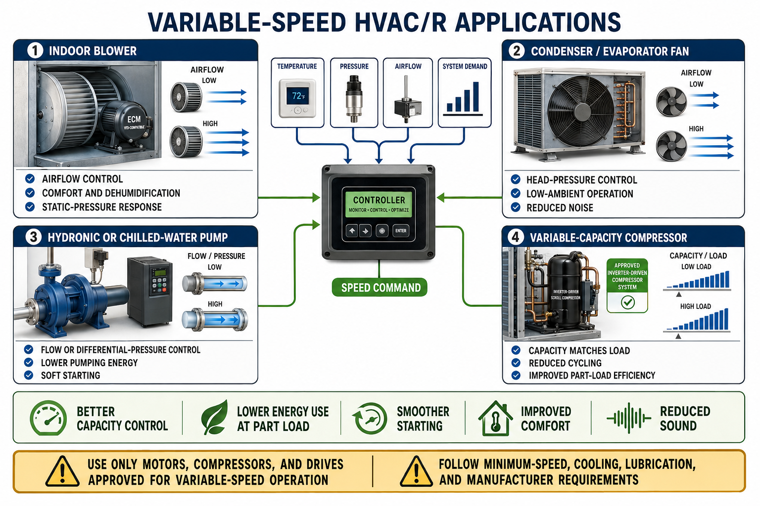
Indoor Blowers
Speed can respond to airflow, duct pressure, temperature, ventilation, staging, comfort, and dehumidification commands.
Condenser and Evaporator Fans
Speed can regulate refrigerant pressure, support low-ambient operation, reduce sound, and match heat-rejection or heat-absorption demand.
Hydronic and Chilled-Water Pumps
Speed can maintain flow or differential pressure as valves and building loads change.
Cooling-Tower Fans
Speed can control leaving-water temperature or condensing conditions while reducing cycling and noise.
Air-Source and Water-Source Systems
Coordinated variable-speed components can match heating or cooling capacity to building demand.
Approved Variable-Capacity Compressors
A manufacturer-matched inverter, compressor, sensors, controls, oil-management strategy, and operating envelope work as one system.
Small Speed Reductions Can Greatly Reduce Fan and Pump Power
For a geometrically unchanged centrifugal fan or pump operating in a region where the affinity-law assumptions apply, flow varies approximately with speed, pressure or head varies with speed squared, and power varies with speed cubed:
At 80% speed, the idealized relationships predict approximately 80% flow, 64% pressure, and 51% power. Actual electrical savings differ because of system static pressure, control position, fan or pump efficiency, motor and drive losses, minimum flow, and operating point.
Do Not Apply the Cube Law Blindly
Systems with substantial static lift or static pressure, changing equipment efficiency, unstable operating regions, bypass flow, minimum-flow requirements, or non-centrifugal loads may not follow the simple idealized power relationship.
An Ordinary Motor VFD Is Not a Universal Compressor Controller
Many variable-capacity compressors use an inverter selected and programmed specifically for the compressor. The controller may manage rotor position, current, speed, acceleration, refrigerant pressure ratio, discharge temperature, motor temperature, oil return, minimum speed, maximum speed, and prohibited operating regions.
Do not connect a standard VFD to a hermetic compressor unless the compressor, drive, control scheme, protection, refrigerant circuit, and application are explicitly approved for that combination. Do not megger through an inverter, apply line power directly to an inverter-only compressor, or substitute a drive based only on voltage and horsepower.
The Drive Needs Both Power and Permission to Run
| Signal or Function | Examples | Service Question |
|---|---|---|
| Run Permissive | Enable contact, safety chain, HOA switch, smoke control, proof interlock, network command | Are all required conditions satisfied and interpreted correctly? |
| Speed Reference | 0–10 VDC, 4–20 mA, potentiometer, keypad, preset speeds, PID output, digital network command | Is the selected reference source correct, scaled properly, and free of wiring faults? |
| Process Feedback | Static pressure, differential pressure, temperature, airflow, flow, refrigerant pressure | Is the sensor accurate, powered, located correctly, and scaled to engineering units? |
| Motor Feedback | Estimated speed, encoder, resolver, current, temperature, torque estimate | Does the configured control mode require feedback, and is it valid? |
| Building Communication | BACnet, Modbus, or manufacturer-specific protocol | Is the drive in local or remote mode, and which source presently has command authority? |
| Safety Function | Safe torque off or approved safety input | Has the function operated, and does it provide the required isolation for the intended work? |
Safe torque off can prevent torque-producing output when correctly designed and validated, but it does not normally remove hazardous voltage from drive input, DC bus, or motor connections. Follow the safety-system documentation and use energy isolation for service.
Programming Must Match the Motor and Process
Motor Nameplate Data
Enter the required voltage, current, frequency, speed, power, power factor, and motor type exactly as the drive procedure requires.
Minimum and Maximum Speed
Limits protect lubrication, cooling, bearings, noise, flow, pressure, fan tip speed, and equipment operation.
Acceleration and Deceleration
Ramp times must suit motor current, load inertia, process stability, stopping method, and DC-bus limits.
Control Mode
Volts-per-hertz, vector, torque, PID, permanent-magnet, and other modes require compatible motors and setup.
Protection
Electronic overload, current limit, temperature inputs, phase-loss response, stall protection, and restart behavior must be coordinated.
Commands and Scaling
Reference source, start source, analog ranges, network control, feedback scaling, and fail-safe actions must match the system sequence.
Record Parameters Before Changing Them
Save or document the original parameter set, firmware, motor data, network settings, and application configuration. A factory reset or unplanned replacement can erase equipment-specific setup and safety behavior.
The Load Can Return Energy to the DC Bus
When a high-inertia fan or pump is commanded to slow faster than it naturally coasts, the motor can act as a generator and return energy to the drive’s DC bus. Bus voltage may rise until the drive extends the deceleration, trips on overvoltage, activates a braking circuit, or transfers energy through a regenerative front end.
Do not shorten deceleration time merely to make the equipment stop faster. Evaluate load inertia, process requirements, overhauling loads, braking resistors, mechanical brakes, dampers or valves, coast-to-stop behavior, and manufacturer recommendations.
Bypass Changes the Power Path and Protection
An HVAC bypass package may allow the motor to operate across the line when the VFD is unavailable. The bypass circuit requires properly interlocked drive and bypass contactors, suitable overload and short-circuit protection, correct phase sequence, and a control sequence that prevents unsafe transfer.
In bypass, the motor normally runs at line frequency and full available speed; drive speed limits and electronic overload functions may no longer protect it. Never transfer a spinning motor between drive and line unless the system is designed for that transfer and all conditions are satisfied.
Use Fault History as Evidence, Not a Parts Verdict
Identify the System
Record drive, motor, load, firmware, bypass, filters, control source, drawings, and approved service instructions.
Read Status and History
Capture active faults, event sequence, commanded frequency, actual output, current, DC-bus value, inputs, and operating hours before resetting.
Inspect the Installation
Check ventilation, temperature, moisture, contamination, terminals, grounding, shielding, cable routing, motor, bearings, and driven load.
Verify Input Power
Measure all applicable input phases and check upstream fuses, contactors, disconnects, and voltage balance using approved methods.
Verify Commands
Confirm run permissives, interlocks, local/remote selection, reference source, sensor scaling, and network authority.
Test by Manufacturer Procedure
Isolate components as directed and evaluate drive, motor, conductors, and mechanical load without exposing electronics to improper tests.
A Fault Code Describes a Condition
| Fault Condition | Possible Causes to Investigate |
|---|---|
| Overcurrent | Short circuit, ground fault, motor or cable damage, stalled load, acceleration too fast, wrong motor data, unstable tuning, or improper switching. |
| DC-Bus Overvoltage | High input voltage, rapid deceleration, overhauling load, failed braking circuit, or line transient. |
| DC-Bus Undervoltage | Low or missing input phase, voltage sag, open fuse, weak connection, undersized source, or input contactor problem. |
| Drive Overtemperature | Blocked cooling, failed fan, high ambient, contamination, enclosure problem, overload, or excessive carrier frequency. |
| Motor Overload | Excess mechanical load, inadequate cooling at low speed, incorrect motor data, current imbalance, wrong connection, or process fault. |
| Ground Fault | Motor insulation, output cable, moisture, contamination, connector damage, or drive output-stage fault. |
| Communication or Reference Loss | Broken conductor, failed sensor, incorrect scaling, network configuration, shielding or grounding issue, or loss of controller power. |
Protect the Drive From Improper Test Voltage and Switching
- Never megger or high-potential test through connected drive electronics.
- Disconnect motor conductors from the drive before an approved insulation-resistance test.
- Do not place power-factor-correction capacitors, surge capacitors, or unapproved filters between the drive and motor.
- Do not switch a conventional contactor on the drive output while the drive is producing output unless specifically designed for it.
- Do not connect line power to VFD output terminals U, V, and W.
- Do not assume swapping input phases changes motor direction; use the drive command or approved output-lead procedure.
- Use PWM-compatible instruments and manufacturer-defined test points for output measurements.
- Reconnect shields, grounds, covers, cooling ducts, and cable separation exactly as required.
Review Questions
1. What are the three main power stages of a common VFD?
The rectifier, DC bus or DC link, and PWM inverter.
2. What primarily changes the synchronous speed of an induction motor?
Changing the VFD output frequency changes synchronous field speed.
3. Why does a VFD normally adjust voltage as it changes frequency?
Voltage is coordinated with frequency to maintain suitable magnetic flux and torque without over-fluxing the motor.
4. At 50% speed, what idealized fan or pump power does the cube relationship predict?
Approximately 12.5% of full-speed power, subject to system and efficiency limitations.
5. Why can the drive remain hazardous after input power is removed?
DC-bus capacitors can store lethal electrical energy until properly discharged.
6. Does interchanging two VFD input phases normally reverse the motor?
No. Output phase sequence is created by the inverter; use the approved drive command or motor-output procedure.
7. Why can rapid deceleration cause a DC-bus overvoltage fault?
The rotating load can drive the motor as a generator and return energy to the DC bus.
8. Why must a variable-capacity compressor use an approved drive system?
The drive, compressor, controls, protection, sensors, lubrication, refrigerant circuit, and operating envelope are engineered as a matched system.
Key Takeaways
- A VFD rectifies AC to DC, stores and filters energy on a DC bus, and inverts it into controlled motor output.
- Output frequency controls synchronous motor speed, while voltage and control strategy support magnetic flux and torque.
- PWM output requires suitable motors, cable practices, grounding, filters, and test instruments.
- Variable-speed fans and pumps can reduce energy at part load, but affinity-law assumptions and system limits matter.
- Approved variable-capacity compressor systems are not interchangeable with ordinary motor-and-VFD combinations.
- Commands, permissives, feedback, programming, motor data, and mechanical load are all part of VFD diagnosis.
- DC-bus capacitors can retain lethal voltage after input power is removed.
- Fault codes identify conditions to investigate; they do not automatically identify a failed component.