Motor Controls and Overload Protection
A complete motor branch circuit uses coordinated devices to isolate power, interrupt short circuits and ground faults, start and stop the motor, and protect the motor from sustained overload. A disconnect, fuse, circuit breaker, contactor, and overload relay may appear in the same circuit, but each performs a different primary function.
Understanding these functions prevents dangerous substitutions and improves diagnosis. A contactor can open motor power without providing overload protection; a conventional branch-circuit fuse or breaker may tolerate normal motor starting current without protecting the motor from every sustained overload; and an overload relay normally opens a control contact rather than directly interrupting a high fault current.
Learning Objectives
Identify Circuit Functions
Distinguish disconnecting, short-circuit and ground-fault protection, motor control, and running-overload protection.
Trace Power and Control Circuits
Follow three-phase motor power through a starter and trace the control path through safeties, overload contacts, and the contactor coil.
Explain Overload Operation
Describe how thermal and electronic overload relays respond to sustained motor-current and heating conditions.
Diagnose Trips Safely
Treat a trip as evidence, verify the cause, and reset only after safe conditions and correct settings are established.
Control Power Off Does Not Prove Motor Power Is Off
Identify Every Source and Verify Every Circuit
Follow the required lockout/tagout procedure, open all applicable disconnecting means, and verify absence of voltage with properly rated test equipment before servicing. Motor-control enclosures can contain line voltage, separately supplied control voltage, transformers, VFD DC-bus energy, heaters, network wiring, and backfed or automatically energized circuits.
A de-energized contactor coil does not make the line side of the contactor safe. Opening a disconnect does not prove its load side is de-energized until tested. Only qualified persons may test exposed energized circuits using the required work practices, PPE, insulated tools, and meter ratings.
One Motor Requires Several Protective and Control Functions
| Function | Typical Device | What It Does | What It Does Not Automatically Do |
|---|---|---|---|
| Isolation | Disconnect switch or suitable circuit breaker | Opens the required supply conductors and provides an approved means of disconnection. | A basic switch does not necessarily provide automatic fault or overload protection. |
| Short-Circuit and Ground-Fault Protection | Fuses or circuit breaker | Interrupts very high fault current and protects the branch circuit and equipment within its ratings. | A conventional branch device selected to permit starting may not provide complete motor running-overload protection. |
| Motor Control | Contactor or controller | Starts and stops the motor by opening or closing the power circuit. | A basic contactor does not sense motor overload or interrupt fault current by itself. |
| Running-Overload Protection | Thermal or electronic overload relay, integral protector, or approved controller function | Responds to sustained overcurrent, heating, phase conditions, or modeled motor temperature according to its design. | A traditional overload relay is not a branch-circuit short-circuit interrupting device. |
| Operating Command | Thermostat, pressure control, BAS, selector switch, or controller | Requests operation when system conditions require it. | An operating control is not an energy-isolating device. |
| Equipment Grounding | Equipment grounding conductor and bonding path | Provides a low-impedance fault-current path and bonds exposed metal. | It is not a normal motor-current conductor or substitute for neutral. |
One Housing May Perform More Than One Function
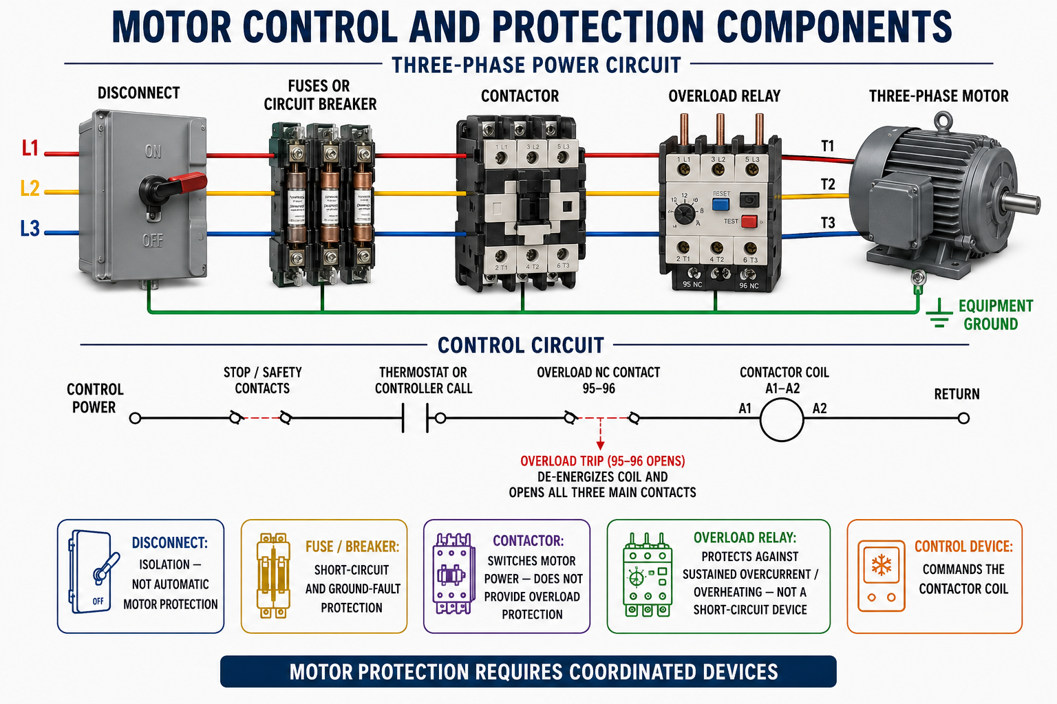
The functional separation shown in the figure is essential, but modern products can combine functions. A listed combination motor controller, self-protected starter, motor-protection circuit breaker, manual motor protector, VFD, or solid-state starter may incorporate several forms of control and protection.
Do not identify capability from appearance or the word “breaker.” Determine the device’s listing, markings, interrupting rating, trip functions, adjustable range, required upstream protection, controller rating, enclosure, and permitted use from current manufacturer documentation and applicable electrical requirements.
Motor Current Passes Through the Main Poles
Disconnect
The disconnect provides the approved means to isolate the motor circuit from its source.
Branch Protection
Fuses or a circuit breaker clear short circuits and ground faults within their application and ratings.
Contactor Main Poles
The energized contactor closes all motor power paths; the released contactor opens them.
Overload Sensors
Motor current passes through heaters, current elements, or electronic current sensors associated with the overload relay.
Motor Windings
The properly connected motor receives the required phase voltage and develops torque.
Equipment Ground
Bonded metal parts provide the required equipment grounding path independent of the normal phase currents.
Line and load designations matter. A contactor commonly labels incoming terminals L1, L2, and L3 and outgoing terminals T1, T2, and T3, but markings vary. Follow the device diagram, maintain required conductor bending space and clearances, and tighten terminals to the specified torque.
A Small Control Current Commands the Contactor
In a traditional electromagnetic starter, control power passes through stop and safety contacts, an operating call, and the overload relay’s normally closed contact before reaching the contactor coil. When that complete path is closed, the coil creates a magnetic field that pulls in the armature and closes the main contacts.
If a safety opens, the operating call ends, control power fails, or the overload relay trips, the coil de-energizes. A spring releases the armature and opens all main contacts. This permits low-power controls to command a higher-power motor circuit while keeping protection and interlocks in series with the coil.
| Control Element | Typical Normal State | Effect on Coil Circuit |
|---|---|---|
| Stop or Safety Contact | Normally closed when conditions are safe | Opens the control path when a stop or unsafe condition occurs. |
| Operating Call | Open with no demand; closed when operation is requested | Completes the call portion of the coil circuit. |
| Overload Trip Contact | Normally closed before an overload trip | Opens after a trip and prevents the contactor from remaining energized. |
| Contactor Coil | De-energized without a complete control path | Pulls in the main contacts when supplied with its rated control voltage. |
| Auxiliary Contact | Depends on design and contactor position | Can provide holding, interlocking, status, staging, or proof functions. |
Coil, Magnetic Assembly, and Contacts Form One Device
Coil
The coil must receive its rated AC or DC voltage. Wrong voltage, frequency, or coil type can cause failure, chatter, overheating, or failure to pull in.
Armature and Core
The magnetic assembly moves the contacts. Dirt, wear, damage, misalignment, or low coil voltage can prevent full closure.
Main Contacts
Main poles carry motor current. Pitting, erosion, welding, contamination, or weak pressure can create voltage drop and phase imbalance.
Auxiliary Contacts
Smaller contacts provide control status, holding, sequencing, or interlocking and are not automatically suitable for motor current.
A contactor that audibly pulls in is not proven good. Measure appropriate voltage across closed poles under load when permitted, inspect all phases de-energized, and compare contact condition and operating data with manufacturer criteria. Never file, dress, lubricate, or replace individual contact parts unless the manufacturer authorizes that service.
Sustained Current Produces a Time-Dependent Trip
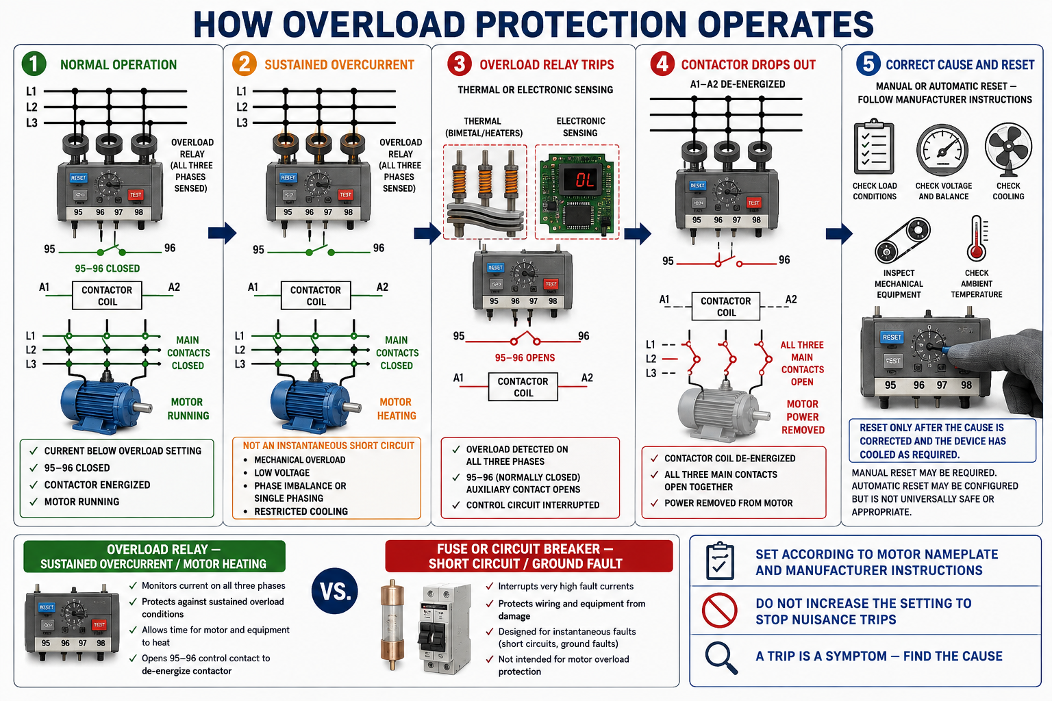
Normal Operation
Current remains within the expected range, the overload contact stays closed, and the contactor remains energized.
Sustained Abnormal Current
Mechanical overload, low voltage, imbalance, single-phasing, stalled load, frequent starting, or restricted cooling increases motor heating.
Overload Relay Trips
Thermal or electronic sensing reaches its trip condition after a time determined by current and device characteristics.
Control Contact Opens
The normally closed overload contact interrupts the contactor-coil circuit.
Contactor Drops Out
The coil releases and all main poles open, removing motor power.
Cause Is Corrected
The system is inspected, repaired, cooled as required, and reset only by the approved procedure.
Different Technologies Model Motor Heating Differently
| Overload Type | Operating Principle | Characteristics to Verify |
|---|---|---|
| Melting-Alloy Thermal | Heater-produced temperature melts an alloy or releases a trip mechanism. | Correct heater selection, enclosure temperature, reset procedure, phase routing, and manufacturer instructions. |
| Bimetallic Thermal | Heated bimetal elements bend and operate the trip mechanism. | Adjustable range, ambient compensation, trip class, reset mode, and phase-loss response. |
| Electronic Overload | Current sensors and electronics calculate or model overload conditions. | Full-load setting, trip class, phase-loss and imbalance features, ground-fault options, motor temperature inputs, and communication. |
| Internal Motor Protector | Temperature or current-sensitive device is located within or on the motor. | Automatic or manual reset, external control requirements, accessibility, and motor/application listing. |
| VFD Electronic Motor Protection | Drive software estimates heating from configured motor data and measured current. | Correct motor parameters, low-speed cooling, bypass protection, multiple-motor arrangement, and external sensor requirements. |
No overload device can compensate for incorrect motor selection, blocked cooling, wrong connections, severe voltage unbalance, excessive ambient temperature, or a mechanical fault outside its sensing and protection design.
Overloads Must Permit Starting but Protect During Abnormal Heating
Overload relays use inverse-time behavior: higher current generally produces a faster trip, while normal acceleration current is allowed for a limited time. Trip class describes a standardized aspect of trip time at a specified multiple of the current setting, but the suitable class depends on motor design, acceleration time, load inertia, and application requirements.
Thermal memory represents heat retained by the motor and protective device. Immediate reset after a trip can be unsafe because the motor may still be hot. Some electronic relays model cooling, some thermal devices require physical cooling, and some systems permit automatic reset.
Automatic Reset Can Cause Unexpected Starting
Use automatic reset only where the motor, equipment, control system, risk assessment, and manufacturer instructions permit it. A reset motor can restart without a person at the equipment, creating electrical, mechanical, pressure, and process hazards.
Use the Motor Data and Applicable Instructions
Set or select overload protection from the actual motor nameplate, motor connection, service factor or temperature-rise information when applicable, controller instructions, installation conditions, and current electrical requirements. Do not copy the setting from a replaced motor, use the branch-circuit breaker rating, or assume the largest adjustable value is acceptable.
Multi-speed, multi-winding, part-winding, wye-delta, VFD, hermetic compressor, and multiple-motor applications can require special sensing locations and settings. A motor connected for a different voltage may have a different line current even though horsepower is unchanged.
Magnitude and Time Require Different Responses
| Condition | Typical Magnitude and Duration | Primary Protective Response |
|---|---|---|
| Normal Starting Current | High but expected for a limited acceleration period | Protective devices coordinate to permit the approved start. |
| Running Overload | Current above normal for seconds or minutes, causing motor heating | Overload protection trips according to its time-current characteristic. |
| Locked Rotor or Failure to Start | Very high sustained current with little or no rotation | Motor protection must interrupt before damaging heating, coordinated with branch protection. |
| Short Circuit | Extremely high fault current rising rapidly | Fuse or circuit breaker interrupts within its rating and coordination. |
| Ground Fault | Unintended current path to ground; magnitude depends on system impedance | Applicable branch or ground-fault protective device interrupts the fault. |
| Single-Phasing | One phase path is lost; remaining currents and motor heating become abnormal | Phase-sensitive overload or other protection operates according to its design. |
The Cause May Be Electrical, Mechanical, or System-Related
Mechanical Overload
Seized bearings, excessive belt tension, pump or compressor problems, rubbing, misalignment, or excessive load increases required torque.
Voltage Problem
Low voltage, voltage unbalance, an open phase, or high-resistance connection can increase current and motor heating.
Incorrect Connection
Wrong voltage connection, missing lead, reversed winding group, or loose terminal can produce abnormal current.
Cooling Problem
Blocked airflow, dirt, failed fan, high ambient temperature, excessive cycling, or low-speed operation can overheat the motor.
Application Problem
Wrong motor, undersized horsepower, excess starts, long acceleration, high system pressure, or operation outside the rated duty can cause trips.
Protection Problem
Wrong heater, setting, trip class, phase routing, ambient condition, wiring, or failed overload device can create improper operation.
Find the Cause Before Resetting
- Record the event. Note operating mode, load, elapsed run time, fault indicators, temperatures, sounds, smells, weather, and previous trips.
- De-energize safely. Apply the required energy-control procedure and verify all power and stored motion are controlled.
- Identify the protective device. Determine exactly which overload, fuse, breaker, VFD, internal protector, or control opened.
- Verify motor and device data. Compare nameplate current, connection, service conditions, overload range, setting, heater, trip class, and reset mode.
- Inspect the power circuit. Check fuses, contactor poles, overload paths, conductors, terminations, discoloration, torque, and evidence of single-phasing.
- Inspect the motor and load. Check cooling, bearings, belts, alignment, fan or pump, compressor conditions, pressure, and mechanical freedom.
- Measure as approved. Evaluate all line voltages and currents, balance, winding condition, insulation, and load performance with suitable instruments.
- Correct the cause. Repair the fault and allow required motor and overload cooling time.
- Reset once under controlled conditions. Restore guards and covers, clear personnel, follow the approved startup, and monitor all phases and system conditions.
Find Where the Expected Voltage Changes
When a contactor will not energize, use the schematic to trace control voltage through each permissive and safety to the coil. Measure across components or from the specified reference as appropriate. A closed switch normally has little voltage across it, while an open switch can have the source voltage across it when the rest of the path is intact.
| Observation | Possible Interpretation | Verification |
|---|---|---|
| Rated voltage across coil, contactor not pulled in | Open or incorrect coil, mechanical binding, wrong frequency, or failed contactor | Verify voltage under load, coil data, resistance by approved method, and mechanical condition de-energized. |
| No voltage across coil | No call, open safety or overload, missing control source, broken conductor, or incorrect reference | Trace the schematic from source to return and identify the open point. |
| Contactor chatters | Low coil voltage, unstable control, loose connection, damaged shading ring, contamination, or wrong coil | Measure voltage during chatter and inspect the control circuit and magnetic assembly safely. |
| Contactor energized, one motor phase missing | Open fuse, burned contact, loose connection, overload-path failure, or conductor fault | Measure all phase voltages at line and load points and inspect de-energized components. |
| Coil repeatedly cycles | Safety cycling, control-voltage drop, pressure or temperature instability, overload reset, or controller logic | Observe the control signal sequence and determine which device opens first. |
Avoid These Protection Mistakes
Using the Contactor as a Disconnect
An open contactor can reclose automatically and may leave its line side energized.
Assuming the Breaker Protects Everything
Motor circuits require coordinated fault, overload, control, and isolation functions.
Bypassing a Safety
Jumping overloads, limits, pressure controls, or interlocks removes protection and can create immediate hazards.
Increasing the Overload Setting
Changing the setting without engineering justification can permit damaging motor temperature.
Resetting Repeatedly
Each restart adds heat and can worsen an electrical, mechanical, or refrigeration-system fault.
Replacing by Appearance
Coil voltage, pole rating, utilization category, interrupting coordination, trip range, trip class, and auxiliary contacts must match.
Review Questions
1. What is the primary purpose of the disconnect?
It provides an approved means to isolate the motor circuit from its electrical source.
2. What is the primary purpose of branch-circuit fuses or a circuit breaker?
They interrupt short-circuit and ground-fault current within their ratings and application.
3. Does a basic contactor provide motor running-overload protection?
No. It switches motor power but requires separate or integrated overload protection.
4. How does a traditional overload relay stop the motor?
Its normally closed control contact opens, de-energizing the contactor coil so the main contacts open.
5. Why does an overload relay not trip instantly at normal starting current?
Its inverse-time characteristic permits the approved acceleration period while responding to sustained damaging current.
6. What does terminal designation 95–96 commonly identify?
It commonly identifies an IEC normally closed overload contact, but the actual device diagram must be verified.
7. Why is automatic reset potentially hazardous?
The motor can restart unexpectedly after the protector cools or the reset condition is satisfied.
8. What should be done after an overload trip?
Record the event, safely isolate the equipment, find and correct the cause, verify settings and cooling, and reset only by the approved procedure.
Key Takeaways
- Motor circuits require coordinated isolation, fault protection, control, and overload protection.
- A contactor switches power but does not by itself sense overload or safely isolate the circuit for service.
- Traditional overload relays open the contactor-coil circuit after a sustained abnormal condition.
- Thermal and electronic overload devices use time-dependent behavior to permit normal starting while limiting damaging heat.
- Combination devices may perform several functions, but their exact listing and ratings must be verified.
- Overload settings come from motor data, device instructions, application conditions, and current electrical requirements.
- An overload trip is a symptom that can originate in the electrical circuit, motor, mechanical load, cooling, or equipment system.
- Never bypass protection, raise settings to stop trips, or repeatedly reset without correcting the cause.