Motor Troubleshooting and Electrical Diagnosis
Effective motor troubleshooting begins with the system, not with an assumption that the motor has failed. A motor that will not start, runs hot, trips protection, draws abnormal current, or delivers inadequate airflow can be responding to a power problem, control fault, incorrect connection, failed capacitor, excessive mechanical load, blocked airflow, refrigeration-system condition, or an internal motor defect.
This lesson organizes diagnosis into a safe, repeatable sequence. It explains de-energized winding and insulation tests, energized voltage and current measurements, three-phase balance calculations, and the limitations of each test so that replacement decisions are supported by evidence.
Learning Objectives
Follow a Diagnostic Sequence
Move from complaint verification and inspection through safe electrical testing, fault isolation, correction, and documentation.
Evaluate Winding Faults
Distinguish open, shorted, and grounded winding conditions and recognize the limits of standard ohmmeters.
Calculate Three-Phase Unbalance
Measure all phase combinations and calculate voltage and current unbalance from the maximum deviation from average.
Reach Evidence-Based Conclusions
Separate motor faults from power, control, connection, load, airflow, and system causes before replacing equipment.
Choose De-Energized Testing Whenever Possible
Resistance Is Never Measured on an Energized Circuit
Disconnect every energy source, apply the required lockout/tagout procedure, release or restrain stored mechanical and pressure energy, discharge capacitors by the approved method, and verify absence of voltage before continuity, resistance, capacitance, or insulation-resistance testing. Remove or isolate connected electronics as required.
Energized voltage, current, control-signal, and power measurements expose the technician to shock, arc-flash, unexpected starting, and moving-equipment hazards. They are performed only by qualified persons when justified by the task and authorized procedures, using properly rated instruments, leads, PPE, barriers, and safe work practices.
Start With the Complaint and End With Verification
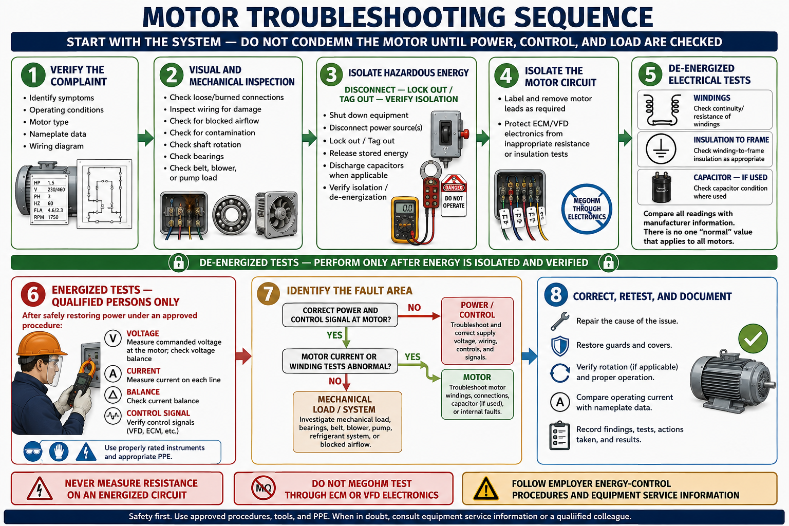
Verify the Complaint
Identify exactly what the equipment does, when it happens, operating conditions, motor type, nameplate data, control sequence, and prior work.
Inspect Before Testing
Look, listen, and smell for loose or burned connections, contamination, blocked cooling, belt or bearing problems, wrong rotation, damaged wiring, and load faults.
Isolate Hazardous Energy
Shut down by the approved sequence, disconnect all sources, lock and tag, control stored energy, and verify the isolation.
Isolate the Motor Circuit
Photograph and label conductors, separate the motor as directed, and protect electronics from inappropriate meter or insulation-test voltage.
Perform De-Energized Tests
Check windings, insulation, capacitors when used, switches, connections, mechanical freedom, and manufacturer-specified components.
Perform Approved Energized Tests
Qualified persons verify commanded voltage, all phase currents, balance, control inputs, and operating behavior under defined conditions.
Identify the Fault Area
Use evidence to classify the cause as power and control, motor and connection, or mechanical load and equipment system.
Correct, Retest, and Document
Repair the cause, restore guards and covers, verify rotation and operation, compare current with ratings, and record results.
Translate the Symptom Into Testable Facts
Descriptions such as “bad motor,” “won’t run,” or “keeps tripping” are conclusions or incomplete symptoms. Determine whether the motor never starts, starts slowly, starts and stops, runs in the wrong direction, runs hot, makes noise, vibrates, draws excessive current, trips immediately, trips after a predictable time, or fails only under a particular system condition.
| Question | Diagnostic Value |
|---|---|
| When did the symptom begin? | Links the fault to installation, electrical work, maintenance, weather, load changes, or gradual deterioration. |
| Does it occur during start or after running? | Separates starting-circuit, acceleration, overload, cooling, and thermal-reset behavior. |
| Which operating mode is active? | Identifies speed taps, relays, VFD commands, stages, reversing circuits, and system loads involved. |
| What protective device operates? | Distinguishes control lockout, internal protector, overload relay, fuse, breaker, or drive fault. |
| What changed recently? | Focuses attention on replacement parts, wiring, settings, bearings, filters, belts, ductwork, valves, or refrigerant service. |
| What are the nameplate and application requirements? | Provides the voltage, phase, frequency, current, speed, capacitor, duty, and connection baseline. |
Many Motor Symptoms Begin Outside the Windings
Connections
Look for loose terminals, overheated insulation, corrosion, damaged plugs, contact erosion, missing hardware, poor crimps, and incorrect lead placement.
Cooling
Check fan blades, shrouds, vents, filters, airflow-over-motor, dirt, ambient temperature, VFD low-speed operation, and enclosure suitability.
Bearings and Shaft
Check noise, end play, roughness, lubrication, seized bearings, bent shaft, rubbing, thrust, and evidence of electrical bearing damage.
Drive Components
Inspect belt tension, pulley and coupling alignment, blower wheel, fan blade, pump, gearbox, guards, base, and soft foot.
System Load
Evaluate pressure, airflow, dampers, valves, filters, coils, refrigerant conditions, compressor load, ice, and process demand.
Environment
Look for water, oil, refrigerant, chemicals, dust, pests, condensation, vibration, heat, and evidence of lightning or surge exposure.
Preserve the Original Circuit Before Disconnecting
Photograph the terminal arrangement, identify the viewing direction, label every conductor, and record jumpers, capacitor leads, overload devices, plugs, shields, grounds, and connector orientation. Do not rely on wire color alone. Compare what is installed with the equipment and motor diagrams before assuming the previous connection was correct.
Disconnect enough of the circuit to prevent parallel paths and backfeed from affecting the test. For VFD, ECM, inverter, and electronic-protection systems, use the manufacturer’s isolation procedure. An ohmmeter reading through a module, capacitor, transformer, or another winding may be stable yet meaningless.
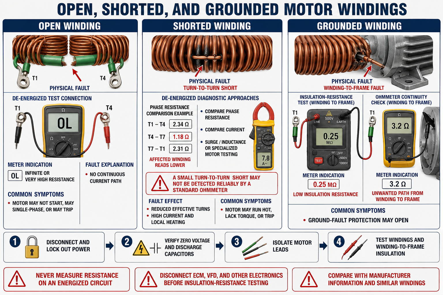
Open, Shorted, and Grounded Are Different Failures
| Fault | Electrical Condition | Possible Symptoms | Diagnostic Limitation |
|---|---|---|---|
| Open Winding | A conductor, internal connection, protector, switch, or terminal interrupts the current path. | No start, single-phasing, no torque, hum, overload trip, or intermittent operation when hot. | An open reading does not identify the physical location or distinguish an open protector without further testing. |
| Turn-to-Turn Short | Insulation failure bypasses part of a winding, reducing effective turns and creating localized current and heat. | High current, low torque, overheating, imbalance, repeated trips, or failure under load. | A small turn short may not create enough resistance change for a standard ohmmeter to detect reliably. |
| Phase-to-Phase Short | Insulation fails between winding phases. | High fault current, protective-device operation, severe heating, or winding damage. | The failure can be intermittent or voltage-dependent and requires approved testing. |
| Grounded Winding | A winding establishes an unintended conductive path to the frame or grounded metal. | Ground-fault or branch protection opens, shock hazard, leakage current, or intermittent trip. | A low-voltage ohmmeter displaying OL does not prove insulation integrity at operating voltage. |
Compare Equivalent Paths Under Equivalent Conditions
Measure isolated winding paths with a meter suited to the expected resistance. Check and compensate for test-lead resistance when appropriate, maintain repeatable probe contact, and record winding temperature because copper resistance increases with temperature.
On a conventional three-lead three-phase motor, all three phase-to-phase readings should be approximately equal. On a single-phase C-S-R compressor, the three readings intentionally differ according to the main and auxiliary winding relationship. Multi-lead, dual-voltage, part-winding, pole-changing, ECM, and inverter motors require their own diagrams and procedures.
Test Voltage, Temperature, and Motor Design Matter
An insulation-resistance tester applies a higher DC test voltage than a standard ohmmeter and measures resistance from isolated windings to the motor frame or between circuits as specified. Results depend on winding temperature, moisture, contamination, motor size and voltage, test duration, test voltage, prior operation, and the manufacturer’s acceptance criteria.
Use only the approved test voltage and connection. Disconnect electronics, capacitors, surge devices, temperature sensors, VFDs, ECM modules, and other sensitive components as directed. After testing, discharge the winding by the approved procedure because it can retain electrical charge.
One Megohm Reading Is Not a Universal Rule
Do not condemn or approve every HVAC/R motor from a single generic resistance threshold. Compare with current manufacturer guidance, applicable standards, temperature correction, previous trend data, and the specific motor and environment.
A Single-Phase Motor Fault May Be External
For PSC, CSIR, and CSCR motors, verify the specified capacitor capacitance, voltage rating, physical condition, wiring, and approved test method. A weak or open capacitor can reduce starting or running torque and increase current without an open motor winding.
Inspect centrifugal switches, potential relays, current relays, PTC devices, electronic start modules, internal protectors, and external overloads according to the motor circuit. Never substitute a capacitor based only on physical size or use a larger capacitance to make a motor start.
Measure the Voltage the Motor Receives Under Command
When energized testing is necessary and authorized, measure voltage at defined circuit points under the operating condition that produces the symptom. For a three-phase motor, measure all three line-to-line combinations using the same instrument. For single-phase equipment, measure across the actual motor supply conductors rather than assuming either conductor’s voltage to ground proves the circuit.
| Test Location | What It Can Reveal |
|---|---|
| Source or Disconnect Line Side | Available supply voltage and an upstream missing phase. |
| Disconnect Load Side | Open switch pole, fuse, connection, or voltage drop through the disconnect assembly. |
| Contactor Line and Load Sides | Open or high-resistance main contact and whether the contactor is commanded closed. |
| Overload and Starter Output | Open power path or voltage actually delivered toward the motor. |
| Motor Terminals | Voltage at the load after conductor and connection drops. |
| Across a Closed Device | Unexpected voltage drop indicating resistance when current is flowing. |
Voltage measured with no load may appear normal through a high-resistance connection. Comparing voltage under starting and running conditions can expose faults that an open-circuit measurement misses.
Current Reflects Voltage, Motor Condition, and Mechanical Load
Measure current on every applicable line under the same stable operating condition and compare it with the nameplate, service data, motor connection, ambient, load, and control output. Current above nameplate does not automatically prove a shorted winding; overload, low voltage, imbalance, wrong connection, excessive pressure, tight bearings, belt tension, or blocked airflow can also increase current.
Current below expected value can indicate low load, missing torque production, incorrect connection, open winding path, low command, VFD reduced speed, or measurement error. Starting current and running current must be interpreted separately.
Calculate Maximum Deviation From the Average
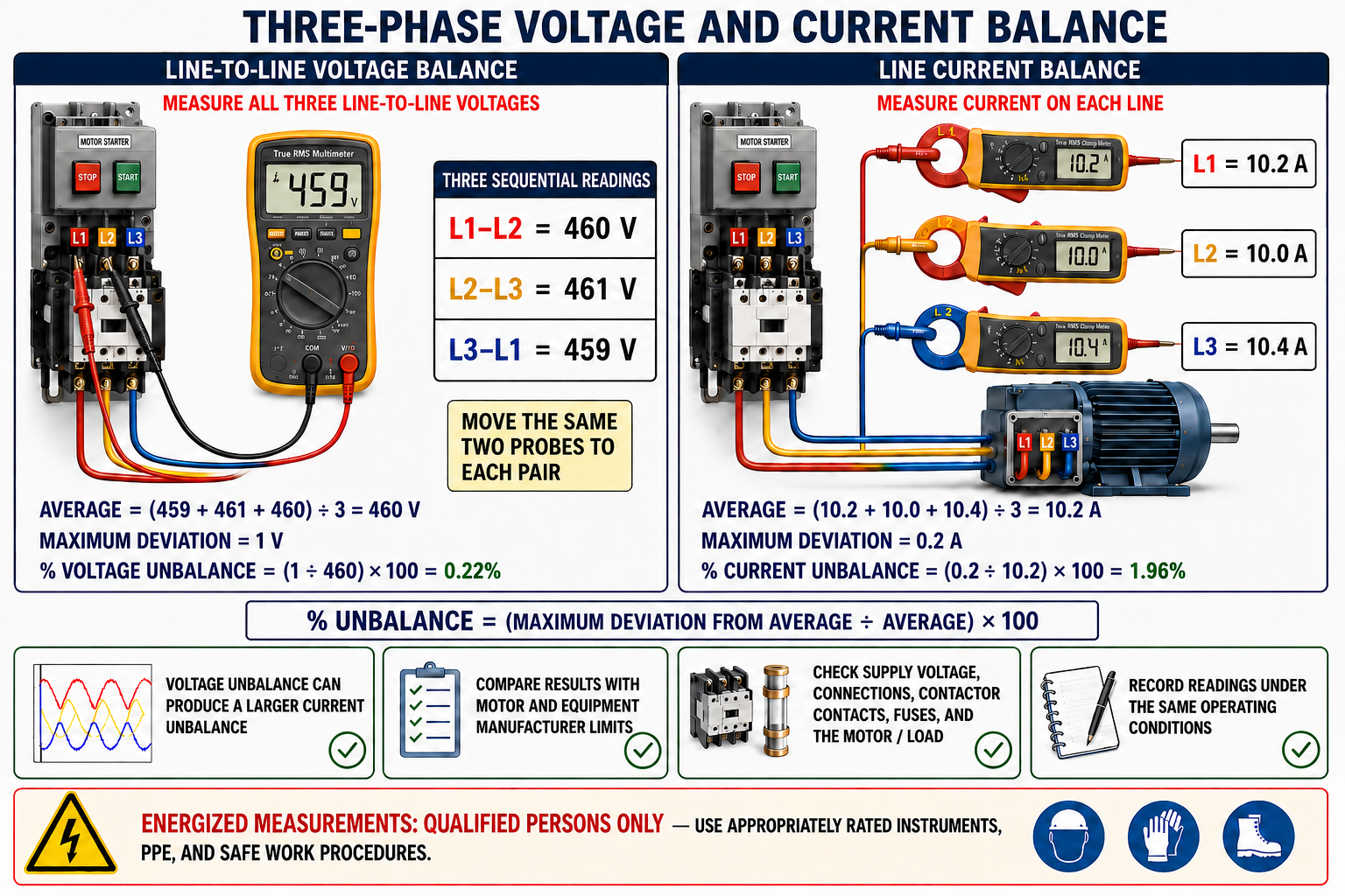
Voltage Example
The three readings are 459 V, 461 V, and 460 V. Their average is 460 V. The maximum deviation from average is 1 V, so voltage unbalance is approximately 0.22%: (1 ÷ 460) × 100.
Current Example
The three readings are 10.2 A, 10.0 A, and 10.4 A. Their average is 10.2 A. The maximum deviation is 0.2 A, so current unbalance is approximately 1.96%: (0.2 ÷ 10.2) × 100.
Voltage unbalance can cause a much larger current unbalance and motor heating. Compare results with the motor, equipment, drive, and power-quality limits supplied by the manufacturers. There is no universal allowable current-unbalance percentage for every motor and operating condition.
Determine Whether the Cause Follows the Line or the Motor
First inspect and measure the supply, fuses, disconnect poles, contactor contacts, overload paths, conductors, terminals, motor winding resistance, and driven load. When manufacturer procedures permit, a controlled lead-rotation test can help distinguish a supply-side voltage problem from a motor-related current problem by observing whether the high-current condition follows the incoming line or remains with the same motor winding position.
This advanced test requires correct documentation, de-energization between lead changes, confirmed rotation, and an application that can safely tolerate the test. Do not perform it on VFD outputs, inverter-driven compressors, ECMs, phase-sensitive loads, or equipment where rotation or lead changes could cause damage.
Do Not Swap Leads Casually
Changing two phases reverses a conventional three-phase motor. Any diagnostic lead rotation must preserve the required phase sequence or be followed by an approved direction check before full operation.
Use Several Measurements to Support Each Conclusion
| Symptom | Areas to Check |
|---|---|
| Motor will not start | Supply, command, safeties, contactor coil and poles, overload, all phases, capacitor or start components, winding continuity, locked load, and VFD/ECM status. |
| Motor starts slowly | Voltage during start, phase loss, capacitor, start switch or relay, motor connection, load inertia, friction, pressure, and starting method. |
| Motor runs hot | Current on all lines, voltage balance, overload, cooling, ambient, starts per hour, mechanical load, VFD minimum speed, and winding condition. |
| Protection trips immediately | Short circuit, ground fault, locked rotor, wrong connection, failed drive/module, incorrect protection, or severe mechanical fault. |
| Protection trips after time | Sustained overload, inadequate cooling, imbalance, low voltage, high ambient, repeated cycling, excessive pressure, or incorrect overload setting. |
| Motor is noisy or vibrates | Bearings, alignment, soft foot, fan or blower, balance, loose mounting, rotor defect, rubbing, electrical imbalance, VFD carrier effects, and driven load. |
| Airflow or pumping is low | Rotation, speed command, wheel or impeller, belt, filters, coil, ducts, valves, static pressure, flow restrictions, and motor torque. |
Condition Tools Support—but Do Not Replace—Electrical Tests
Thermal imaging can reveal a hot fuse clip, contactor pole, terminal, bearing, winding area, or cooling restriction while equipment operates under appropriate load. Emissivity, reflections, viewing angle, enclosure state, airflow, and load affect interpretation. Similar components under similar conditions provide useful comparisons.
Vibration measurements can help distinguish imbalance, misalignment, looseness, bearing defects, resonance, belt problems, and some rotor conditions. Reliable trending requires consistent sensor location, direction, mounting, speed, and load. Sound, heat, and vibration alone do not prove an electrical winding failure.
Separate Power, Command, Electronics, Motor, and Load
For an ECM, verify line power at the power connector and the correct low-voltage or communicating command at the control connector. For a VFD, capture fault history, input power, DC-bus information, command source, reference, output status, motor parameters, and mechanical load before clearing the fault.
Do not use PSC assumptions on electronically controlled motors. Similar connectors can have different pinouts, PWM output can confuse general-purpose meters, and replacement modules may require programming. Follow the exact service procedure and do not megger through electronics.
Avoid Conclusions That the Test Does Not Support
Condemning From a Symptom
A tripped overload or no-start complaint identifies a condition, not automatically a failed motor.
Testing Without Isolation
Parallel paths and electronics can alter readings or be damaged by the test instrument.
Using One “Normal” Resistance
Motor design, horsepower, voltage, connection, and temperature change winding resistance.
Trusting an OL Ground Check
A low-voltage ohmmeter may not reveal insulation failure that appears at operating voltage.
Calling Low Resistance a Turn Short
Large motors naturally have low winding resistance, and small turn shorts may escape a standard ohmmeter.
Measuring Only One Phase
Three-phase diagnosis requires all voltage combinations and all line currents under the same conditions.
Ignoring the Mechanical Load
Bearings, belts, fans, pumps, compressors, pressure, and airflow can overload an electrically sound motor.
Resetting Without Evidence
Repeated resets add heat, erase fault context, and can intensify equipment damage and safety hazards.
A Repair Is Not Complete Until Operation Is Proven
- Confirm all conductors, jumpers, capacitors, shields, grounds, and connectors are restored to the verified diagram.
- Torque connections as specified and replace terminal covers, guards, panels, plugs, and strain relief.
- Remove tools, temporary test equipment, jumpers, and personal protective devices according to procedure.
- Clear personnel and restore energy using the approved startup sequence.
- Verify rotation before extended operation when applicable.
- Measure voltage, current on every phase, command, speed, temperature, airflow or pressure, vibration, and system performance as appropriate.
- Confirm protection, safeties, interlocks, controls, and automatic operating modes function correctly.
- Document the complaint, conditions, measurements, calculations, cause, repair, settings, parts, and final results.
Review Questions
1. Why should motor troubleshooting begin with the complete system?
Power, control, connection, protection, mechanical load, airflow, and refrigeration conditions can produce symptoms that resemble motor failure.
2. What must occur before measuring winding resistance?
All hazardous energy must be isolated, capacitors discharged, absence of voltage verified, and the motor isolated from parallel paths and sensitive electronics.
3. Can a standard ohmmeter reliably detect every turn-to-turn short?
No. A small turn short may cause too little resistance change and may require specialized testing or operating evidence.
4. Does OL from a terminal to the frame prove good insulation?
No. A low-voltage ohmmeter test does not prove insulation integrity under operating or approved insulation-test voltage.
5. How is percent unbalance calculated?
Divide the maximum deviation from the average by the average and multiply by 100.
6. Why must all readings be taken under the same operating conditions?
Load, voltage, speed, command, temperature, and system pressure can change the readings and invalidate comparisons.
7. Does high motor current automatically prove a shorted winding?
No. Mechanical overload, low or unbalanced voltage, wrong connection, excessive pressure, bearing problems, and cooling faults can also increase current.
8. What completes a troubleshooting repair?
Correct the root cause, safely restore the equipment, verify rotation and performance, test protection and controls, and document the results.
Key Takeaways
- Begin with the system and verify the complaint before condemning a motor.
- Inspect power connections, controls, cooling, bearings, driven load, and operating conditions before electrical isolation.
- Open, shorted, and grounded windings are different faults requiring different evidence.
- A standard ohmmeter cannot reliably detect every turn short or prove insulation integrity at operating voltage.
- Insulation testing requires the approved voltage, temperature context, discharge procedure, and complete isolation of electronics.
- Three-phase diagnosis requires all three line-to-line voltages and all three line currents under the same conditions.
- Percent unbalance uses the maximum deviation from average, but acceptance limits come from manufacturer and application information.
- Repair the root cause, verify complete operation and protection, and document the evidence.