HVAC/R Motor Review and Comparison
HVAC/R equipment uses several motor families because a small evaporator fan, indoor blower, hermetic compressor, chilled-water pump, condenser fan, and variable-air-volume system do not have the same torque, efficiency, speed-control, supply, or control requirements.
This final lesson compares the motor families covered throughout the course and reviews selection, wiring, capacitors, three-phase operation, ECMs, VFDs, controls, overload protection, and troubleshooting. The goal is not to memorize one “best” motor, but to identify the motor and system, understand how they are intended to operate, and test them using the correct information.
Learning Objectives
Compare Motor Families
Relate construction, starting method, torque, efficiency, speed control, and HVAC/R applications.
Select and Replace Correctly
Use the complete motor, equipment, load, control, mechanical, and environmental requirements.
Review Essential Relationships
Apply synchronous speed, slip, C-S-R resistance, wye/delta, VFD, and three-phase balance concepts.
Choose the Right Diagnostic Path
Separate power, control, motor, capacitor, electronics, protection, mechanical-load, and system faults.
Motor Service Combines Electrical and Mechanical Hazards
De-Energize, Lock Out, and Verify
Identify every source, follow the required lockout/tagout procedure, discharge capacitors, wait for specified DC-bus discharge, control stored pressure and mechanical motion, and verify absence of voltage before resistance, continuity, capacitance, connection changes, or disassembly. A thermostat, contactor, controller stop command, VFD keypad, or BAS command is not an energy-isolating device.
Only qualified persons may perform justified energized measurements using the required procedures, PPE, barriers, tools, and properly rated instruments. Restore grounding, terminal covers, guards, fan panels, belt guards, plugs, strain relief, and equipment enclosures before operational testing.
Application Requirements Determine the Motor
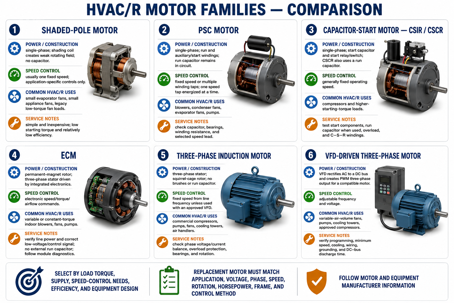
| Motor Family | Starting and Operating Method | Typical HVAC/R Use | Primary Service Focus |
|---|---|---|---|
| Shaded-Pole | A shading coil creates a weak rotating field; no capacitor is used. | Small evaporator, appliance, and low-torque fan loads. | Correct voltage, free bearings, winding continuity, airflow, and correct replacement direction. |
| Split-Phase | An auxiliary winding provides starting phase displacement and a switch or relay removes it after acceleration. | Legacy fans, pumps, and moderate starting loads. | Start winding, centrifugal switch or relay, overload, bearings, and acceleration. |
| PSC | A run capacitor remains in series with the auxiliary winding during starting and running. | Blowers, condenser fans, evaporator fans, pumps, and some compressors. | Specified capacitor, winding condition, speed tap, bearings, airflow, and load. |
| CSIR | A start capacitor and auxiliary winding are disconnected after acceleration. | Compressors and loads requiring greater starting torque. | Start capacitor, relay or switch, overload, winding condition, supply, and mechanical load. |
| CSCR | A start capacitor disconnects; a run capacitor and auxiliary winding remain energized. | Higher-torque compressor and refrigeration applications. | Both capacitors, starting relay, winding circuit, overload, and compressor conditions. |
| ECM | Integrated electronics commutate a permanent-magnet rotor motor and regulate programmed output. | Indoor blowers, fans, pumps, and variable or constant-torque/airflow applications. | Separate line power and control command, connectors, programming, static pressure, module, and motor. |
| Three-Phase Induction | A three-phase stator field induces current in a squirrel-cage rotor. | Commercial compressors, pumps, fans, cooling towers, and air handlers. | All phase voltages and currents, connections, overload, bearings, load, cooling, and rotation. |
| VFD-Driven Motor | A drive rectifies AC, stores DC-bus energy, and creates variable-frequency output for a compatible motor. | Variable-air-volume fans, pumps, towers, and approved variable-speed equipment. | Drive power and commands, parameters, cooling, grounding, motor suitability, output limits, and DC-bus safety. |
Identify the Stationary and Rotating Parts
Stator
The stationary laminated core and windings create the magnetic field. Winding arrangement determines poles, phase, voltage connection, and operating behavior.
Induction Rotor
A squirrel-cage rotor contains conductor bars shorted by end rings. Stator-field motion induces rotor current and torque.
Permanent-Magnet Rotor
An ECM or permanent-magnet motor uses rotor magnets that follow an electronically controlled stator field and can generate voltage when driven.
Air Gap
Clearance between stator and rotor permits rotation and magnetic coupling. Bearing wear or misalignment can cause rubbing and uneven magnetic forces.
Bearings and Shaft
Bearings support the rotor and shaft while the shaft transfers torque. Alignment, lubrication, thrust, belt tension, and contamination affect life.
Frame and Cooling
The enclosure, fan, vents, airflow-over-motor, ambient rating, and mounting protect and cool the motor according to its application.
All Motors Produce Torque Through Magnetic Interaction
Current through stator windings creates magnetic fields. The motor design determines how a usable rotating field is produced and how the rotor responds. A shaded-pole motor uses a shading coil, a split-phase motor uses winding impedance, a capacitor motor uses phase shift from capacitance, three-phase power naturally creates a rotating field, and an ECM or VFD uses electronic switching and control.
An induction motor runs below synchronous speed so relative motion can induce rotor current. Percent slip is [(Ns − Nr) ÷ Ns] × 100%. An ECM with a permanent-magnet rotor and electronic commutation is not evaluated using ordinary induction-motor slip in the same way.
The Auxiliary Winding Creates Starting Direction and Torque
| Design | Auxiliary-Winding Circuit | Disconnects After Start? | External Capacitor |
|---|---|---|---|
| Split-Phase | Different winding resistance and reactance create phase displacement. | Normally yes | None in the basic design |
| PSC | Run capacitor remains in series with the auxiliary winding. | No | Run capacitor |
| CSIR | Start capacitor provides strong starting phase displacement. | Start circuit normally disconnects | Start capacitor |
| CSCR | Start and run capacitance are used during start; run capacitance remains afterward. | Start capacitor disconnects | Start and run capacitors |
Start and Run Capacitors Are Not Interchangeable
| Characteristic | Start Capacitor | Run Capacitor |
|---|---|---|
| Duty | Short-time starting duty | Continuous or long-duration motor duty |
| Typical Capacitance | Relatively high | Lower than a comparable start capacitor |
| Construction | Commonly electrolytic and not intended to remain energized | Designed for continuous AC service |
| Circuit Control | Relay, switch, PTC, or electronic starting device removes it | Remains in the approved auxiliary-winding circuit |
| Replacement | Match approved capacitance, voltage rating, duty, and application | Match the motor-specified capacitance and use an equal or higher approved voltage rating |
A physically swollen, leaking, or damaged capacitor is defective, but a normal appearance does not prove correct capacitance. Isolate and discharge it by the approved method before testing. Never increase capacitance merely to make a motor start or substitute a start capacitor for a run capacitor.
The Motor and Compressor Share a Pressurized Shell
A hermetic compressor encloses the motor, bearings, oil, internal wiring, and compression mechanism within a welded shell. Single-phase compressors commonly expose common, start, and run terminals, but physical terminal position is not universal.
Terminal Venting Can Release Refrigerant, Oil, and Debris
De-energize and verify before removing a terminal cover or molded plug. Never energize a compressor with the approved terminal cover or plug removed, and do not reset a breaker or replace a fuse without first checking for an electrical fault.
For a conventional three-lead three-phase compressor, all three isolated phase-to-phase winding-resistance readings should be approximately equal. Absolute values and tolerances come from manufacturer information and winding temperature, not a universal field number.
Different Motors Change Output in Different Ways
| Method | How Output Is Selected | Critical Limitation |
|---|---|---|
| PSC Winding Taps | One discrete winding tap is energized at a time. | Unused speed leads are insulated individually; never energize two taps together. |
| ECM Selectable Inputs | Low-voltage or line-voltage inputs request programmed torque, speed, or airflow values. | Connector, signal type, and output strategy vary by motor. |
| Communicating ECM | A control board sends manufacturer-specific digital commands. | Correct power does not prove a valid command or compatible programming. |
| VFD | The drive varies output frequency and voltage to a compatible motor. | Minimum speed, cooling, motor insulation, load, and drive parameters control the acceptable range. |
| Approved Inverter Compressor | A matched inverter and compressor follow an equipment-specific capacity strategy. | Do not substitute a general-purpose VFD or apply line voltage directly to an inverter-only compressor. |
For centrifugal fans and pumps where the affinity-law assumptions apply, flow varies approximately with speed, pressure or head with speed squared, and power with speed cubed. Static pressure, static lift, efficiency changes, minimum flow, and equipment limits make actual results different from the ideal relationships.
Three Displaced Phases Create a Rotating Field
Balanced three-phase waveforms have equal frequency and magnitude and are separated by 120 electrical degrees. Their currents in stator windings arranged around the motor create a continuously rotating resultant magnetic field. Phase sequence determines direction; interchanging any two phases reverses a conventional three-phase motor after safe de-energization.
| Balanced Connection | Voltage Relationship | Current Relationship |
|---|---|---|
| Wye | Vline = √3 × Vphase | Iline = Iphase |
| Delta | Vline = Vphase | Iline = √3 × Iphase |
These relationships apply to balanced sinusoidal quantities. The motor nameplate and lead diagram—not the generic wye/delta figure—determine actual six-, nine-, or twelve-lead connections, dual-voltage arrangements, and starting methods.
Electronic Motors Require Power, Command, and Correct Programming
ECM Power Path
AC input is rectified to a DC bus, and inverter switches electronically commutate a multi-phase stator around a permanent-magnet rotor.
ECM Diagnostic Split
Verify line power at the power connector and the correct low-voltage or communicating command at the control connector.
VFD Power Path
The rectifier, DC link, and PWM inverter convert fixed-frequency AC into adjustable motor output.
VFD Stored Energy
DC-bus capacitors can retain lethal voltage after input power is removed. Wait the specified time and verify voltage.
System Response
A constant-airflow ECM or VFD may increase speed as system resistance rises, so high speed can indicate restricted airflow rather than motor failure.
Replacement
Control interface, motor data, programming, direction, horsepower, airflow profile, connectors, cooling, and manufacturer approval must match.
Coordinated Devices Perform Different Jobs
| Device | Primary Function | Diagnostic Reminder |
|---|---|---|
| Disconnect | Provides an approved means of isolation. | Opening it does not prove de-energization until tested. |
| Fuse or Circuit Breaker | Provides applicable short-circuit and ground-fault protection. | A conventional branch device is not automatically complete running-overload protection. |
| Contactor | Electrically switches motor power. | A pulled-in contactor can still have a burned or open main pole. |
| Overload Relay | Responds to sustained motor overload or modeled heating. | A trip is a symptom; verify current, voltage, load, cooling, setting, and phase condition. |
| Operating Control | Commands operation based on thermostat, pressure, BAS, or sequence. | It is not an energy-isolating device. |
| Safety or Interlock | Prevents or stops operation when an unsafe or unproven condition exists. | Never bypass it to make equipment run. |
Combination motor controllers and drives may integrate several functions. Verify the exact listing, ratings, protection, upstream requirements, and manufacturer’s instructions rather than judging capability from appearance.
Match the Complete Application
Electrical
Voltage, phase, frequency, full-load current, horsepower, efficiency, service factor, capacitor, insulation, and VFD suitability.
Mechanical
Frame, mounting, shaft diameter and length, rotation, bearings, thrust, pulley or coupling, and available space.
Performance
Speed, torque, starting method, duty, starts per hour, airflow or pumping requirements, and load inertia.
Control
Speed taps, contactor, overload, ECM input, communication protocol, VFD, sensors, programming, and sequence.
Environment
Enclosure, ambient temperature, moisture, refrigerant, chemicals, dust, altitude, airflow-over-motor, and hazardous location.
Equipment Approval
OEM cross-reference, compressor approval, fan or pump application, code requirements, and warranty conditions.
Start With the System and Narrow the Fault Area
- Verify the complaint. Define the symptom, operating mode, timing, nameplate, circuit, and recent changes.
- Inspect visually and mechanically. Check connections, cooling, contamination, bearings, belts, load, and rotation.
- Isolate hazardous energy. Disconnect, lock and tag, discharge capacitors, control motion, and verify zero voltage.
- Isolate the circuit correctly. Label conductors and disconnect electronics before resistance or insulation tests.
- Perform de-energized tests. Evaluate windings, insulation, capacitor, starting devices, contactor poles, and mechanical freedom.
- Perform necessary energized tests safely. Qualified persons verify voltage, current, balance, control command, frequency, and load.
- Identify the fault area. Separate power/control, motor/connection, and mechanical/system causes.
- Correct, retest, and document. Restore guards, verify rotation and performance, test protection, and record final results.
Understand What Each Meter Reading Proves
| Test | Useful Finding | Important Limitation |
|---|---|---|
| Continuity | Confirms a path below the meter’s continuity threshold. | Does not establish correct resistance, balance, insulation, or loaded operation. |
| Winding Resistance | Identifies opens, C-S-R relationships, and substantial differences among equivalent phases. | Lead resistance and temperature matter; small turn shorts may be undetectable. |
| Ohmmeter to Frame | Can reveal a low-resistance grounded winding. | An OL display does not prove insulation integrity under operating voltage. |
| Insulation Resistance | Evaluates isolated winding insulation using a specified DC test voltage. | Acceptance depends on motor, voltage, temperature, time, condition, and manufacturer criteria. |
| Operating Voltage | Reveals missing phases, voltage drop, unbalance, and actual supply under load. | Requires qualified energized work and all relevant phase combinations. |
| Operating Current | Reflects motor torque demand, phase condition, connection, and system load. | High current does not automatically prove a shorted winding. |
Choose the Most Likely Diagnostic Direction
Scenario 1: A PSC condenser-fan motor hums, starts when spun, and then runs hot.
Safely verify the specified run capacitor and its circuit, supply voltage, winding condition, bearings, fan blade, load, and current. Do not automatically condemn the motor or install a larger capacitor.
Scenario 2: A three-phase pump motor trips its overload after several minutes.
Measure all three voltages and currents under the same load, calculate balance, inspect contactor and connection drops, verify overload settings, and evaluate pump pressure, valves, bearings, alignment, and mechanical load.
Scenario 3: An ECM blower has correct line power but does not run.
Verify the correct control command, connector pinout and seating, equipment safeties, configuration, motor and module diagnostics, mechanical load, and manufacturer test procedure.
Scenario 4: A VFD reports DC-bus overvoltage during stopping.
Investigate deceleration time, load inertia, overhauling load, input voltage, braking circuit, and programmed stop mode. Do not repeatedly reset or shorten the ramp further.
Scenario 5: A compressor breaker has tripped.
Do not immediately reset it. De-energize and inspect the terminal assembly, test the isolated winding and insulation by the approved method, verify external controls and components, and evaluate the compressor and refrigeration-system load.
Scenario 6: A new three-phase fan runs backward.
Confirm the required direction and viewing end, determine that a direction test is safe, de-energize and verify zero voltage, interchange any two approved motor supply phases, and retest with guards restored.
Course Review Questions
1. What four factors determine synchronous motor-field speed?
The formula uses supply frequency and pole count: Ns = 120f ÷ P. The constant 120 converts cycles and pole pairs into revolutions per minute.
2. Why does an induction motor operate below synchronous speed?
Relative motion between the field and rotor conductors is required to induce rotor current and produce torque.
3. Which single-phase motor uses no capacitor and a shading coil?
The shaded-pole motor.
4. Which capacitor remains in a PSC circuit during normal operation?
The run capacitor remains in series with the auxiliary winding.
5. What is the single-phase compressor winding-resistance relationship?
C-R is lowest, C-S is middle, S-R is highest, and C-R + C-S is approximately S-R.
6. How many PSC speed taps should be energized at one time?
Only the intended speed tap; unused leads are insulated individually.
7. What two inputs must usually be separated during ECM diagnosis?
Line-voltage power and the low-voltage or communicating control command.
8. What reverses a conventional three-phase motor?
Interchanging any two supply phases after proper de-energization reverses the phase sequence and rotation.
9. What are the three primary VFD power stages?
Rectifier, DC bus or DC link, and inverter.
10. Why can a VFD remain hazardous after input power is removed?
DC-bus capacitors can retain lethal stored voltage.
11. What is the main difference between branch fault protection and overload protection?
Branch protection interrupts short-circuit and ground-fault current, while overload protection responds to sustained motor current and heating conditions.
12. Can a standard ohmmeter reliably detect every shorted turn?
No. A small turn-to-turn short may require specialized testing and supporting operating evidence.
13. What measurements are required for three-phase balance?
Measure all three line-to-line voltages and current in all three lines under the same operating conditions.
14. Does normal winding resistance prove a motor is mechanically sound?
No. Bearings, rotor, shaft, fan, pump, compressor, and driven load can fail while winding resistance remains normal.
15. What information governs the final motor decision?
The motor and equipment nameplates, wiring diagrams, manufacturer service information, measured operating conditions, application requirements, and complete diagnostic evidence.
What You Should Carry Into the Field
- Identify the motor family and circuit before selecting tests or replacement parts.
- Motor torque comes from magnetic interaction, but different motor families create and control the rotating field differently.
- Starting torque, running efficiency, speed control, supply, and load determine the suitable motor.
- Capacitors, relays, switches, electronics, contactors, overloads, and VFDs are parts of the motor system and can create motor-like symptoms.
- Three-phase diagnosis requires complete phase voltage, current, connection, winding, load, and rotation information.
- ECM and VFD diagnosis requires both power and command verification and protection of electronics from inappropriate testing.
- Never replace or condemn a motor from one symptom or one meter reading.
- Work safely, follow the specific equipment information, correct the root cause, verify complete operation, and document the result.