Introduction to HVAC/R Capacitors
Capacitors are used throughout HVAC/R equipment to store electrical energy, affect current and voltage relationships, and help many single-phase motors develop the torque required to start and run. They are found with compressors, condenser-fan motors, blower motors, evaporator-fan motors, pumps, and other equipment loads.
Modern inverter-driven equipment also contains high-voltage DC bus capacitors. Although these components share the basic ability to store electrical energy, their construction, circuit function, polarity, operating conditions, and service hazards differ from those of conventional motor capacitors.
Learning Objectives
Explain Basic Capacitor Construction
Identify the conductive plates, dielectric material, terminals, and electric field involved in storing separated electrical charge.
Interpret Capacitance
Define capacitance, recognize the farad and microfarad, and understand what a capacitor’s marked capacitance value represents.
Describe AC Phase Relationships
Explain how a capacitor affects current and voltage timing and why this effect is useful in single-phase motor circuits.
Recognize HVAC/R Applications and Hazards
Distinguish the broad roles of run, start, dual run, and DC bus capacitors and recognize that stored electrical energy may remain after power is removed.
Capacitors Perform Several Different Jobs
Conventional HVAC/R motor capacitors are most commonly associated with single-phase compressors, blowers, condenser fans, and refrigeration evaporator fans. Depending on the motor and equipment design, a capacitor may remain in the circuit during operation, be used only during startup, or share two separate capacitor sections in one enclosure.
Inverter-driven mini-splits, variable-capacity heat pumps, electronically controlled refrigeration systems, and variable-frequency drives use capacitors for a different purpose. Their DC bus capacitors smooth rectified DC voltage and store energy for the inverter switching stage that controls the compressor or motor.
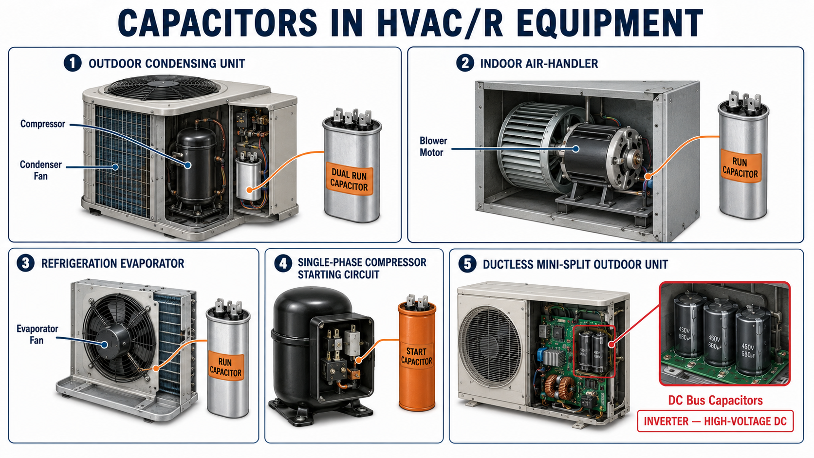
Run Capacitors
A run capacitor is a continuous-duty AC component that remains connected while the applicable motor operates. It is commonly used with permanent split capacitor motors and PSC-type compressors.
Dual Run Capacitors
A dual run capacitor combines separate compressor and fan capacitor sections in one enclosure. The two sections share a common capacitor terminal.
Start Capacitors
A start capacitor is an intermittent-duty AC component that provides additional phase shift and starting torque. It must be removed from the circuit after startup.
DC Bus Capacitors
DC bus capacitors store energy and reduce voltage ripple between a rectifier and inverter switching stage. These polarized high-voltage components require specialized service precautions.
Two Conductive Surfaces Are Separated by a Dielectric
At its most basic level, a capacitor contains two conductive surfaces separated by an insulating material called a dielectric. Each conductive surface connects to a different terminal. The dielectric prevents normal direct current flow from passing through the capacitor as though it were a closed wire.
When voltage is applied, electrons accumulate on one conductive surface while electrons are removed from the other. This separation of charge establishes an electric field across the dielectric. Energy is stored in that electric field rather than by allowing the two conductive surfaces to touch.

| Part or Concept | Function | Service Significance |
|---|---|---|
| Conductive Surfaces | Hold separated electrical charges when voltage is applied. | Damage to the conductive material can reduce effective capacitance or create an internal fault. |
| Dielectric | Insulates the conductive surfaces while allowing an electric field to develop between them. | Heat, excessive voltage, moisture, age, or contamination can damage the dielectric and change capacitor performance. |
| Terminals | Connect the capacitor’s internal elements to the external circuit. | Loose, overheated, corroded, or incorrectly connected terminals can cause equipment symptoms even when the internal capacitor element is not the original fault. |
| Electric Field | Stores energy while charge remains separated across the dielectric. | Stored energy may remain after the external power source is disconnected. |
| Enclosure and Seal | Protect the capacitor element from physical damage and environmental exposure. | Swelling, leakage, venting, corrosion, or heat damage requires further evaluation and correction. |
Capacitance Describes the Ability to Store Separated Charge
Capacitance describes how much separated electrical charge a capacitor can store for a given applied voltage. The basic unit of capacitance is the farad, abbreviated F. One farad is much larger than the values commonly used for conventional HVAC/R motor capacitors.
HVAC/R capacitor values are normally expressed in microfarads. One microfarad is one-millionth of a farad. The correct symbol is µF, although older equipment labels, service literature, and trade usage may use MFD to mean microfarads.
Capacitance Value
A capacitor marked 5 µF has a different capacitance from one marked 45 µF. The correct value is determined by the motor and equipment design rather than by capacitor size or appearance.
Dual Capacitance Value
A dual run capacitor marked 45 + 5 µF contains a 45-µF compressor section and a separate 5-µF fan section. The plus sign separates the two capacitance ratings; it is not a polarity marking.
Marked Tolerance
The tolerance states how far the measured capacitance may vary from the nominal value. The allowable tolerance must be read from the actual capacitor and approved equipment information.
Capacitance Measurement
A capacitance meter applies a controlled test signal and calculates capacitance from the component’s electrical response. Testing procedures are covered later in this section.
Capacitance Is Not the Same as Voltage Rating
The microfarad rating describes capacitance. The voltage rating describes the maximum continuous voltage for which the capacitor is designed under its specified conditions. Both ratings matter, but they describe different properties.
The Applied Voltage Repeatedly Changes Direction
With alternating current, the applied voltage continually changes magnitude and polarity. The capacitor charges in one direction, releases energy as the voltage changes, and then charges in the opposite direction. This repeating process produces current in the external circuit even though the dielectric separates the capacitor’s internal conductive surfaces.
In an ideal capacitor, current leads the voltage across the capacitor by 90 electrical degrees. This means the current waveform reaches corresponding points in its cycle one-quarter cycle before the capacitor-voltage waveform.
A real motor circuit contains winding resistance, inductive reactance, capacitor reactance, and other electrical characteristics. The actual phase relationship is therefore determined by the complete circuit and should not be assumed to be an ideal 90 degrees.
Voltage Is Applied
The supply establishes an electric field and separated charge across the capacitor’s dielectric.
Voltage Changes
As the AC waveform rises, falls, and reverses polarity, the amount and direction of stored charge also change.
External Current Flows
Charging and discharging produce current in the conductors connected to the capacitor terminals.
The Circuit Gains Phase Separation
In a motor circuit, the capacitor helps establish a different current timing in the auxiliary winding than in the main winding.
Phase Separation Helps Produce Starting Direction and Torque
A single-phase supply does not naturally create the same rotating magnetic field produced by a balanced three-phase supply. Many single-phase motors therefore use a main winding and an auxiliary winding arranged at different physical positions in the stator.
Placing a correctly selected capacitor in series with the auxiliary winding changes the current timing in that winding relative to the main winding. The separated winding currents and physical winding positions produce a rotating magnetic effect that establishes starting direction and develops torque.
Permanent Split Capacitor Motors
A PSC motor keeps its run capacitor and auxiliary winding energized during both starting and running. The capacitor supports the motor’s designed phase relationship throughout operation.
Capacitor-Start Motors
A capacitor-start motor uses a start capacitor to produce greater starting torque. A switch, relay, or electronic device removes the start capacitor after the motor accelerates.
Capacitor-Start, Capacitor-Run Motors
A CSCR motor uses both start and run capacitance. The start capacitor is removed after acceleration while the run capacitor remains in the operating circuit.
Hermetic Compressors
Single-phase compressors may use PSC, CSIR, CSCR, or manufacturer-specific starting arrangements. The compressor model and approved wiring information determine the correct components.
Review the Motor Foundation
For a detailed explanation of main and auxiliary windings, phase shift, and single-phase starting torque, review Single-Phase Motor Fundamentals. Later capacitor lessons will apply those relationships to specific run and start circuits.
A Capacitor May Remain Charged After Power Is Removed
Opening a disconnect removes the external supply but does not automatically eliminate energy already stored in a capacitor. The amount of retained energy depends on the capacitor, circuit, discharge path, equipment design, and time since power was removed.
Before handling or testing a conventional motor capacitor, identify and disconnect every power source, follow the applicable lockout/tagout procedure, verify absence of voltage, and use the equipment or capacitor manufacturer’s approved discharge method. After discharge, verify terminal voltage again before removing conductors or touching the component.
Never Assume That Waiting Alone Made the Capacitor Safe
A failed bleeder resistor, open circuit, incorrect wiring, or other condition may allow charge to remain. Verify the electrical state with properly rated test equipment and follow the approved procedure rather than relying on elapsed time, appearance, or an indicator light.
Conventional Motor Capacitors
Run and start capacitors require controlled discharge and voltage verification before testing or replacement. Do not create an uncontrolled arc by shorting the terminals with a screwdriver.
Inverter DC Bus Capacitors
DC bus capacitors may retain lethal voltage after incoming AC power is removed. Observe the manufacturer’s discharge time and verify the DC bus at the specified test points before service.
Multiple Power Sources
Controls, interconnected drives, backup supplies, and other circuits may provide additional energy sources. Use the equipment diagram to identify the complete isolation procedure.
Qualified Service Procedures
Capacitor work exposes technicians to electrical and stored-energy hazards. Follow applicable electrical-safety requirements, employer procedures, equipment instructions, and required personal protective equipment.
Capacitor Knowledge Improves Diagnosis
A Motor Symptom Is Not Proof
A motor that hums, starts slowly, overheats, or fails to run may have a capacitor problem, but low voltage, defective controls, damaged windings, loose connections, or mechanical binding can produce similar symptoms.
Appearance Is Not a Complete Test
Swelling, leakage, corrosion, or heat damage requires attention, but a capacitor that looks normal may still have incorrect capacitance or fail under operating stress.
Ratings Are Not Interchangeable
Physical size and terminal shape do not establish an acceptable replacement. Capacitance, voltage, tolerance, duty, terminals, mounting, temperature, and manufacturer requirements must be evaluated.
The Complete Circuit Matters
Correct diagnosis includes the power supply, controls, capacitor, motor windings, connections, overload protection, mechanical load, and equipment operating conditions.
Avoid These Errors
“A Capacitor Is a Battery”
Both components can store energy, but they operate differently. A capacitor stores separated charge in an electric field and can charge and discharge rapidly.
“Current Passes Through the Dielectric”
The dielectric is an insulator. AC current in the external circuit results from the capacitor repeatedly charging and discharging as voltage changes.
“Every Capacitor Is Polarized”
Conventional AC motor capacitors are nonpolarized. Inverter DC bus capacitors are commonly polarized electrolytic components whose positive and negative connections must be observed.
“Every Capacitor Is Continuous Duty”
Run capacitors are designed for continuous operation in approved applications. Start capacitors are designed for brief intermittent duty and must be removed after startup.
“A Larger Capacitor Gives More Power”
Installing a different capacitance changes motor current and phase relationships and may damage the capacitor, motor, or equipment. Use the specified value.
“Power Off Means the Capacitor Is Safe”
A capacitor may retain hazardous stored energy after the external supply is disconnected. Discharge and voltage verification are still required.
Review Questions
1. What are the three basic elements of a simple capacitor?
Answer: A simple capacitor has two conductive surfaces, a dielectric separating those surfaces, and terminals that connect the conductive surfaces to the external circuit.
2. Where is energy stored in a capacitor?
Answer: Energy is stored in the electric field established across the dielectric while electrical charge remains separated.
3. What is the common unit used for conventional HVAC/R capacitor values?
Answer: Conventional HVAC/R capacitor values are commonly expressed in microfarads, abbreviated µF. Older labels and service information may use MFD to mean microfarads.
4. What does a 45 + 5 µF dual run capacitor rating describe?
Answer: It describes two separate capacitor sections: a 45-µF compressor section and a 5-µF fan section that share a common capacitor terminal.
5. In an ideal capacitor, how does current relate to the voltage across the capacitor?
Answer: Current leads the capacitor voltage by 90 electrical degrees, or one-quarter cycle.
6. Why is a capacitor used with the auxiliary winding of many single-phase motors?
Answer: The capacitor changes the auxiliary-winding current timing relative to the main winding, helping establish starting direction and develop motor torque.
7. What is the main duty difference between a run capacitor and a start capacitor?
Answer: A run capacitor is designed to remain in the approved operating circuit, while a start capacitor is an intermittent-duty component that must be removed after startup.
8. Why must a capacitor be treated as a stored-energy device after power is disconnected?
Answer: The capacitor may retain separated charge and hazardous voltage after the external power source is removed.
9. Does a normal physical appearance prove that a capacitor is electrically good?
Answer: No. A capacitor may look normal while having incorrect capacitance, excessive internal losses, an open circuit, or a failure that appears only under operating stress.
10. Why are conventional motor capacitors and inverter DC bus capacitors not interchangeable?
Answer: They have different construction, polarity, ratings, circuit functions, operating conditions, and service hazards.
Lesson 1 Summary
- A capacitor contains conductive surfaces separated by an insulating dielectric.
- Separated charge establishes an electric field in which electrical energy is stored.
- The farad is the basic unit of capacitance, but conventional HVAC/R capacitor values are usually expressed in microfarads.
- The symbol µF means microfarad, and MFD is also commonly used in older HVAC/R labeling and literature.
- A dual capacitance marking identifies two separate capacitor sections rather than electrical polarity.
- In an ideal capacitor, current leads capacitor voltage by 90 electrical degrees.
- Actual motor-circuit phase relationships depend on the capacitor, motor windings, and the complete connected circuit.
- A correctly selected capacitor helps many single-phase motors establish starting direction and develop torque.
- Run capacitors are continuous-duty components, while start capacitors are intermittent-duty components.
- Dual run capacitors combine separate fan and compressor capacitor sections with a shared terminal.
- Inverter DC bus capacitors smooth rectified DC and store energy for the inverter switching stage.
- Conventional AC motor capacitors are nonpolarized, while many DC bus capacitors are polarized.
- A capacitor may retain hazardous electrical energy after external power is disconnected.
- Safe service requires energy isolation, approved discharge procedures, and verification of terminal voltage.
- Capacitor diagnosis must include the complete power, control, motor, connection, and mechanical system.