Single-Phase Motor Fundamentals
Single-phase electrical power is widely available in residential and light-commercial HVAC/R equipment, but a conventional single-phase induction motor does not naturally develop a definite starting direction from its main winding alone. The motor therefore requires a method of creating an additional magnetic effect during starting.
This lesson explains the main winding, auxiliary winding, phase displacement, starting torque, and common starting methods used by single-phase motors. These principles provide the foundation for the shaded-pole, split-phase, PSC, capacitor-start, and single-phase compressor motors examined in the lessons that follow.
Learning Objectives
Explain the Starting Problem
Describe why the magnetic field produced by one single-phase stator winding does not establish a definite starting direction.
Identify the Two Windings
Recognize the main winding and auxiliary winding and explain their physical and electrical relationship in the stator.
Explain Phase Displacement
Describe how winding design, resistance, inductance, capacitance, or shading creates magnetic effects at different times and positions.
Compare Starting Methods
Distinguish the basic starting principles of shaded-pole, split-phase, PSC, capacitor-start, and electronically controlled motors.
One Alternating Current Does Not Establish a Starting Direction
Alternating current in the main stator winding produces a magnetic field that repeatedly increases, decreases, and reverses polarity as the current alternates. At standstill, this pulsating field does not by itself establish whether the rotor should begin turning clockwise or counterclockwise. The opposing starting effects balance, so the motor has no useful net starting torque.
If only the main winding is energized, a typical single-phase induction motor may hum and draw high current while the rotor remains stationary. It is not safe to demonstrate this condition by manually spinning a connected fan or blower. A stalled motor can overheat rapidly, and exposed energized conductors and moving components present serious hazards.
Two Magnetic Axes Help Establish Rotation
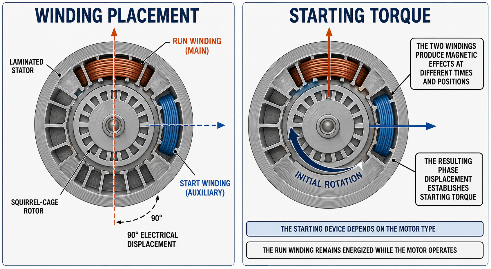
Many single-phase induction motors use a main winding and an auxiliary winding placed at different magnetic positions in the stator. The main winding is sometimes called the run winding because it remains energized during normal motor operation. The auxiliary winding provides the additional magnetic effect needed to develop starting torque.
| Motor Part | Basic Function | Important Distinction |
|---|---|---|
| Main Winding | Produces the primary stator magnetic field and remains energized while the motor operates. | It is commonly called the run winding, although the motor’s documentation determines the correct terminal and lead identification. |
| Auxiliary Winding | Produces a second magnetic effect displaced from the main-winding effect to establish starting torque. | It may disconnect after starting or remain energized, depending on motor design. |
| Stator Core | Supports the windings and provides a laminated magnetic path. | The winding locations establish separate magnetic axes around the stator. |
| Squirrel-Cage Rotor | Receives induced current and develops torque through interaction with the stator field. | It is not directly connected to the external single-phase supply. |
Position and Timing Work Together
The two winding magnetic axes are displaced around the stator. This physical arrangement is commonly described in electrical degrees because the magnetic relationship depends on winding placement and motor pole configuration, not merely on an angle measured with a protractor. A diagram may show the axes at 90 electrical degrees even though that should not be interpreted as a universal 90-degree mechanical spacing for every motor.
Physical displacement alone is not enough. The currents in the main and auxiliary winding circuits must also be displaced in time. Differences in winding resistance and inductance, a capacitor in series with the auxiliary winding, or a shorted shading coil can delay or advance one magnetic effect relative to another.
Physical Displacement
The winding magnetic axes occupy different positions around the stator so their fields act on the rotor from different directions.
Time Displacement
The main and auxiliary circuit currents do not reach corresponding values at exactly the same time, so their magnetic fields peak at different times.
Combined Effect
The two displaced magnetic effects create a sweeping or rotating-field effect that establishes the direction of initial rotor torque.
Starting Torque
The field induces rotor current, and interaction between the stator and rotor fields accelerates the rotor in the established direction.
From Standstill to Running Speed
Power Is Applied
Current begins flowing through the main winding and through the starting circuit provided by the specific motor design.
Fields Are Displaced
Winding location and circuit characteristics cause the main and auxiliary magnetic effects to occur at different positions and times.
Starting Torque Develops
The combined stator field establishes a direction, induces rotor current, and produces torque on the squirrel-cage rotor.
The Rotor Accelerates
Rotor speed rises while remaining below synchronous speed, and the motor develops the torque required to accelerate the connected load.
The Starting Circuit Changes if Required
A switch or relay may disconnect a start winding or start capacitor, while a PSC motor keeps its auxiliary winding and run capacitor energized.
The Motor Carries the Load
The running motor maintains rotation while operating with the slip needed to induce rotor current and produce load torque.
A Failed Starting Circuit Can Damage the Motor
If the auxiliary circuit, capacitor, relay, switch, supply, or mechanical load prevents acceleration, the motor may remain at or near locked-rotor current. De-energize the equipment and diagnose the cause rather than allowing repeated starting attempts or bypassing a protective device.
Different Motor Designs Create the Required Displacement Differently
| Motor Design | Method Used to Establish Starting Torque | Auxiliary Circuit During Operation | Typical HVAC/R Use |
|---|---|---|---|
| Shaded-Pole | A shorted copper shading coil delays the magnetic effect in part of each stator pole. | The shading coil remains part of the magnetic structure; there is no separate capacitor or disconnecting switch. | Small, low-starting-torque fan applications. |
| Resistance-Start Split-Phase | Different resistance-to-reactance characteristics create a current displacement between the main and auxiliary windings. | The auxiliary winding is normally disconnected after the motor accelerates. | Some blowers, pumps, and other moderate-starting-torque loads. |
| Permanent Split Capacitor | A run capacitor in series with the auxiliary winding provides phase displacement. | The auxiliary winding and run capacitor remain energized during starting and running. | Blowers, condenser fans, evaporator fans, and pumps. |
| Capacitor-Start Induction-Run | A start capacitor in series with the auxiliary winding provides increased starting phase displacement and torque. | The start capacitor and auxiliary winding are disconnected by a relay or switch after acceleration. | Compressors, pumps, and other higher-starting-torque loads. |
| Capacitor-Start Capacitor-Run | Start and run capacitance provide strong starting torque and suitable running characteristics. | The start capacitor is removed after acceleration; the auxiliary winding continues operating through the run capacitor. | Single-phase compressors and other demanding loads. |
| Electronically Controlled | Electronic switching controls current in multiple stator windings or phases. | Operation depends on the motor module, programmed control, and equipment command signals. | ECM blowers, fans, pumps, and inverter-driven compressors. |
The Component Name Indicates Its Intended Function
Start Capacitor
A start capacitor is designed for short-duration use during acceleration. It normally provides much higher capacitance than a run capacitor and must be removed from the circuit at the proper time.
Run Capacitor
A run capacitor is designed for continuous AC operation in an approved motor circuit. Its capacitance and voltage rating must match the motor and equipment requirements.
Centrifugal Switch
A centrifugal mechanism responds to rotor speed and opens electrical contacts to remove the start circuit after the motor accelerates. It closes again as the motor slows toward standstill.
Starting Relay
A current, potential, solid-state, or other approved relay can control a compressor or motor start circuit. The correct type, ratings, connections, and application are essential.
Internal Overload
A thermal overload may interrupt motor current when winding temperature or current conditions exceed its design response. It is protection, not a routine operating control.
Electronic Module
An electronic motor module may create the required phase sequence and regulate torque or speed. Conventional winding and capacitor assumptions may not apply.
Start and Run Capacitors Are Not Interchangeable
Use only the capacitor type and ratings specified for the motor. A start capacitor left energized can overheat and fail, while a run capacitor with an incorrect microfarad value can reduce torque, increase current, alter speed or efficiency, and shorten motor life.
The Starting Relationship Establishes Direction
The direction of initial torque depends on the order in which the displaced magnetic effects act around the stator. In a reversible split-phase or capacitor motor, direction is commonly changed by reversing the connections of the auxiliary winding relative to the main winding. Reversing both windings together does not reverse their relationship and therefore does not normally reverse the motor.
Not every single-phase motor is field reversible. Shaded-pole direction is normally fixed by pole construction, some motors provide only one approved rotation, and many ECMs require an electronic command or a specific module configuration. Always follow the motor and equipment wiring information.
Starting Symptoms Point to a System, Not Just One Component
Motor Hums but Does Not Start
Possible causes include low or missing voltage, a failed capacitor, open auxiliary winding, failed relay or switch, incorrect wiring, tight bearings, a bound load, or a damaged motor.
Motor Starts Slowly
Check supply voltage under starting load, the specified capacitor, starting components, connections, bearings, and the driven load. Prolonged acceleration increases heating.
Overload Opens During Starting
Repeated trips may indicate failure to accelerate, excessive load, low voltage, incorrect components, frequent cycling, winding damage, poor cooling, or an unsuitable replacement.
Motor Starts in the Wrong Direction
Verify the required rotation and viewing end, motor reversibility, auxiliary-winding connections, blade or wheel installation, and the applicable wiring diagram.
Start Component Remains Energized
A failed centrifugal switch, relay, wiring error, incorrect relay application, or motor that never reaches transfer speed can overheat the start winding or start capacitor.
Motor Restarts After Cooling
An internal overload may have opened and reset, but the reset does not prove the motor is good. Identify the electrical, thermal, airflow, control, or mechanical condition that caused operation.
Do Not Hand-Start an Energized Motor
Never spin a fan blade, blower wheel, pulley, coupling, or shaft by hand while the motor is energized. Follow the required energy-control procedure before mechanical inspection and use approved electrical tests appropriate to the identified motor and control system.
Avoid These Errors
“Single-Phase Power Produces No Magnetic Field”
The main winding produces an alternating magnetic field. The starting problem is that this field alone does not establish a definite starting direction at standstill.
“Auxiliary Always Means Start-Only”
The auxiliary winding disconnects in some designs but remains energized through a run capacitor in a PSC motor.
“Every Single-Phase Motor Uses a Capacitor”
Shaded-pole and resistance-start split-phase motors can establish starting torque without a capacitor, while electronically controlled motors use another approach.
“Every Capacitor Is a Start Capacitor”
Start and run capacitors have different intended duties. Identify the capacitor by its function, ratings, and motor documentation.
“Reversing the Supply Reverses the Motor”
Reversing both winding connections together does not change their relative magnetic sequence. Reversal requires the manufacturer-specified connection change.
“A Humming Motor Only Needs a Capacitor”
A failed capacitor is one possibility, but the complete supply, start circuit, windings, controls, bearings, and mechanical load must be evaluated.
Review Questions
1. Why does the main winding alone not provide useful starting torque at standstill?
Answer: Its single-phase alternating field does not establish a definite starting direction, so the opposing starting effects balance at standstill.
2. What two basic conditions allow the main and auxiliary windings to establish starting torque?
Answer: Their magnetic axes are displaced in position, and their currents or magnetic effects are displaced in time.
3. What is another common name for the auxiliary winding?
Answer: It is also called the start winding in some documentation and training material.
4. Does the auxiliary winding always disconnect after starting?
Answer: No. It disconnects in some resistance-start and capacitor-start designs, but it remains energized through the run capacitor in a PSC motor.
5. How does a shaded-pole motor create a delayed magnetic effect?
Answer: A shorted copper shading coil surrounds part of each pole and delays the magnetic effect in the shaded portion.
6. What happens to the start capacitor in a capacitor-start induction-run motor?
Answer: It is connected during acceleration and then removed from the circuit by an approved switch or relay.
7. How is a reversible split-phase motor commonly reversed?
Answer: The auxiliary-winding connections are reversed relative to the main winding according to the manufacturer’s diagram.
8. Why should a humming motor not automatically be diagnosed as having a failed capacitor?
Answer: Low voltage, an open winding, failed relay or switch, incorrect wiring, tight bearings, a bound load, or another motor fault can produce a similar symptom.
Lesson 4 Summary
- A single energized main winding produces an alternating magnetic field but does not establish a definite starting direction at standstill.
- Many single-phase induction motors use a main winding and an auxiliary winding to develop starting torque.
- The main winding is also commonly called the run winding.
- The auxiliary winding is also called the start winding in some documentation and course material.
- The winding magnetic axes occupy different positions around the stator.
- The starting method causes the winding currents or magnetic effects to be displaced in time.
- The combined displaced fields establish initial direction and induce rotor current that produces torque.
- Shaded-pole, resistance-start, PSC, capacitor-start, and electronic motors create the required starting effect differently.
- A PSC motor keeps its auxiliary winding and run capacitor energized during operation.
- CSIR motors remove the start capacitor and auxiliary winding after acceleration.
- CSCR motors remove the start capacitor but continue operating the auxiliary winding through a run capacitor.
- Start and run capacitors have different duties and are not interchangeable.
- A failed starting circuit can keep the motor near locked-rotor current and cause rapid overheating.
- Motor direction, starting components, and lead connections must be determined from the applicable manufacturer information.
- A starting problem requires evaluation of the supply, controls, starting components, windings, bearings, and driven load.