Motor Nameplates and Replacement Requirements
A motor nameplate identifies the electrical, mechanical, and thermal conditions for which the motor was designed. Correctly reading this information allows an HVAC/R technician to compare field measurements with rated values, recognize an unsuitable application, and select a replacement that can safely drive the equipment.
Horsepower is only one part of motor selection. Voltage, phase, frequency, full-load current, speed, rotation, frame, shaft, mounting, duty, enclosure, ambient temperature, insulation, thermal protection, capacitor requirements, control compatibility, and equipment airflow may all determine whether a replacement is acceptable.
Learning Objectives
Read Nameplate Ratings
Identify horsepower, voltage, phase, frequency, current, speed, service factor, duty, temperature, insulation, and protection information.
Interpret Application Details
Recognize rotation, frame, shaft, mounting, enclosure, cooling, and capacitor requirements that affect installation and operation.
Compare a Replacement
Use the original motor, equipment data, wiring diagram, and manufacturer information to evaluate a proposed replacement.
Avoid Selection Errors
Explain why horsepower, physical size, wire color, or a motor’s ability to fit are not enough to establish suitability.
Begin With the Ratings Assigned by the Manufacturer
The nameplate is the starting point for identifying a motor. It provides rated information rather than a prediction of every measurement under every operating condition. For example, nameplate amperage normally represents current at rated load, rated voltage, and rated frequency. An unloaded or lightly loaded motor may draw less current, while an overloaded or abnormal motor may draw more.
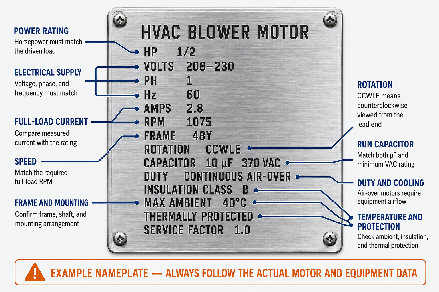
The Replacement Must Be Compatible With the Power Supply
| Nameplate Item | What It Means | How the Technician Uses It |
|---|---|---|
| Voltage (V or VOLTS) | The supply voltage or voltage range for which the motor is rated. | Confirm compatibility with the equipment supply and use the correct connection on a dual-voltage motor. |
| Phase (PH) | Identifies whether the motor is designed for single-phase or three-phase power. | Match the available supply and equipment control arrangement. Single-phase and three-phase motors are not interchangeable without an approved system redesign. |
| Frequency (Hz) | The supply frequency at which the ratings apply. | Match the power source or approved drive output. Frequency affects synchronous speed and motor performance. |
| Full-Load Amperes (FLA or AMPS) | The current associated with rated output under the specified nameplate conditions. | Compare with properly measured operating current and use the applicable equipment and protection requirements. |
| Locked-Rotor Amperes or Code | Indicates starting-current information for motors on which it is provided. | Evaluate starting requirements, controls, conductors, voltage drop, and protective-device application using the applicable instructions and standards. |
| Capacitor | Identifies the required capacitance and minimum voltage rating when the motor uses a specified external capacitor. | Match the rated microfarads and use the specified type with an equal or higher permitted voltage rating. Follow the motor and equipment instructions. |
| Efficiency and Power Factor | Describe how the motor uses electrical input at specified operating conditions. | Use these values when application, energy, electrical-system, or replacement requirements call for them. |
Dual-Voltage Does Not Mean Automatic Voltage Selection
Many dual-voltage motors require specific lead connections for the applied voltage. Identify the actual supply, follow the motor connection diagram, and ensure that all unused leads are individually insulated and secured as directed. An incorrect connection can cause weak torque, excessive current, overheating, or immediate winding damage.
Horsepower, Torque, and Speed Must Match the Load
Horsepower
Rated horsepower describes the motor’s mechanical output capability at the stated conditions. The replacement must be suitable for the driven load and equipment design; installing a larger motor does not correct an overloaded or mechanically defective system.
Full-Load RPM
Nameplate RPM is the expected shaft speed at rated load, voltage, and frequency. For an induction motor, this speed is below synchronous speed because slip is required to produce torque.
Starting Torque
The motor must accelerate the connected load from rest. A replacement with inadequate starting characteristics may hum, start slowly, cycle on its overload, or fail even if its horsepower rating appears correct.
Load Characteristics
A blower, propeller fan, pump, belt drive, and compressor impose different torque requirements. Use a motor approved for the equipment and the type of load being driven.
Physical Compatibility Is More Than Whether the Motor Fits
| Requirement | What Must Be Confirmed | Why It Matters |
|---|---|---|
| Rotation | Clockwise, counterclockwise, or reversible operation and the end from which rotation is viewed. | The same shaft direction appears opposite when viewed from opposite ends. Incorrect rotation reduces or eliminates useful airflow or fluid movement. |
| Frame and Mounting | Frame designation, diameter, bolt pattern, base, resilient rings, belly band, face, flange, and mounting position. | The motor must mount securely and align correctly with the driven equipment. |
| Shaft | Diameter, length, flat, keyway, thread, and location relative to the mounting surface. | The fan blade, blower wheel, pulley, coupling, or compressor mechanism must attach correctly without unsafe modification. |
| Motor Length and Clearance | Overall dimensions, lead exit, terminal box, capacitor location, guards, and service clearances. | A motor may have the correct frame diameter yet interfere with the cabinet, wheel, guard, wiring, or access panel. |
| Connection to the Load | Direct drive, belt drive, coupling, fan blade, blower wheel, or other approved attachment. | Alignment, hub position, belt tension, blade pitch, and load condition affect current, vibration, bearing life, and performance. |
Rotation Abbreviations Require a Viewing Reference
Abbreviations such as CWLE and CCWLE describe rotation when viewed from the lead end, while CWSE and CCWSE describe rotation when viewed from the shaft end. Do not assume the viewing direction. Read the complete marking and verify actual equipment rotation before returning the system to service.
The Motor Must Survive Its Operating Environment
Duty Rating
Continuous, intermittent, or time-limited duty identifies the intended operating pattern. A replacement must be rated for the equipment’s run time, cycling, starting frequency, and load.
Air-Over Cooling
An air-over motor depends on airflow from the driven blower or fan for cooling. Operating it outside the intended air stream or with inadequate airflow can cause overheating even when current is not obviously excessive.
Maximum Ambient
The ambient rating establishes the surrounding temperature condition for which the motor is designed. Equipment compartments, outdoor locations, refrigeration cases, and condenser sections can impose very different conditions.
Insulation Class
The insulation system is designed for specified thermal limits. Insulation class is not permission to ignore high current, blocked cooling, excessive ambient temperature, or frequent cycling.
Enclosure
Open, drip-proof, totally enclosed, fan-cooled, and other enclosure types provide different levels of cooling and environmental protection. Select the enclosure specified for the location and equipment.
Thermal Protection
A nameplate may identify internal thermal protection, but the replacement must still be compatible with the equipment’s overload and control scheme. Never bypass an overload or protective device.
Service Factor Is Not Extra Horsepower for Routine Design
Service factor is a multiplier associated with operation under the nameplate conditions specified by the manufacturer. A 1-horsepower motor with a 1.15 service factor may have a service-factor load capability of 1.15 horsepower under those conditions, but operation above rated horsepower increases temperature and can reduce expected motor life.
A service factor of 1.0 provides no nameplate overload margin above rated horsepower. A replacement should be selected to carry the normal equipment load at its rated output rather than relying on service factor to compensate for an undersized motor, restricted airflow, tight bearings, incorrect belt tension, abnormal system conditions, or another unresolved problem.
Match the Entire Motor to the Entire Application
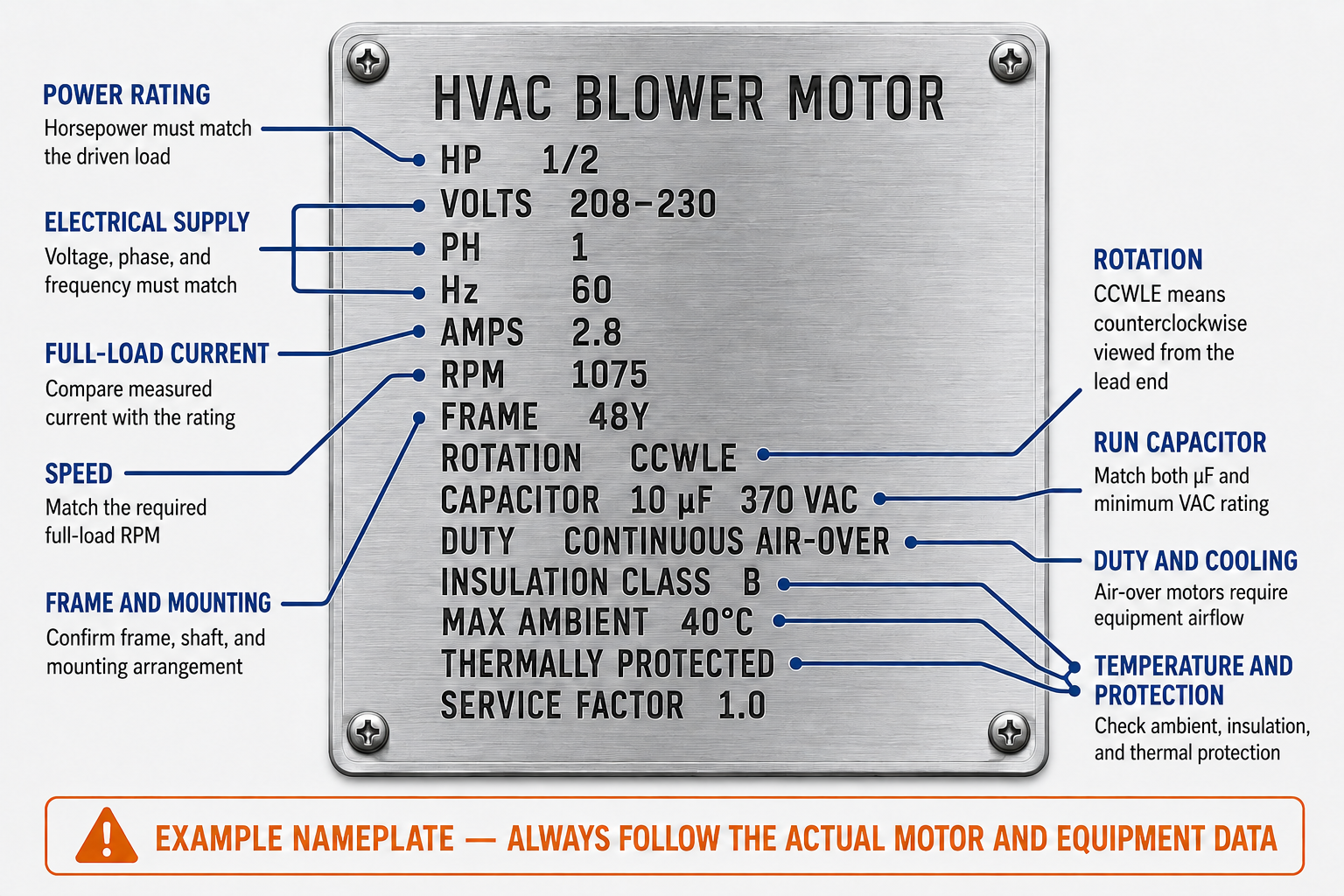
Identify the Original Motor
Record the manufacturer, model or part number, all nameplate ratings, lead markings, rotation, mounting, shaft dimensions, and capacitor information.
Consult the Equipment Data
Check the equipment model and serial numbers, wiring diagram, parts list, service literature, and manufacturer replacement information.
Identify Why the Motor Failed
Inspect the power supply, controls, capacitor, airflow, fan or blower, bearings, belt, mounting, contamination, water exposure, and driven load before installing a replacement.
Compare Every Requirement
Match electrical ratings, output, speed, torque, rotation, frame, shaft, mounting, duty, cooling, enclosure, temperature, protection, capacitor, and control compatibility.
Connect From the New Diagram
Use the replacement motor’s instructions and the equipment diagram. Do not assume that replacement lead colors or terminal positions match the old motor.
Verify Operation
Confirm correct rotation, secure mounting, normal sound and vibration, required airflow or fluid movement, appropriate current, and proper control and overload operation.
Universal Replacement Does Not Mean Universal Application
A replacement motor may support several voltages, speeds, rotations, mounting arrangements, or capacitor choices, but it must still be configured exactly as approved for the specific equipment. Follow the replacement motor instructions and equipment manufacturer requirements rather than assuming a factory lead color, mounting hole, or speed tap is correct.
Some Motors Depend on Equipment-Specific Conditions
PSC Capacitor Requirements
Use the capacitance specified for the replacement motor, not merely the value found beside the failed motor. The microfarad rating must match the motor requirement, and the capacitor voltage rating must meet the specified minimum.
Multi-Speed Motors
Confirm the number of speeds, available speed taps, required airflow, heating and cooling connections, and treatment of unused leads. Lead colors and relative speeds are not universal.
ECMs
An ECM may require a specific motor, electronic module, programmed operating profile, communication signal, or manufacturer replacement procedure. Physical fit and line-voltage compatibility do not establish functional compatibility.
Inverter- and VFD-Driven Motors
The motor must be approved for the drive, output waveform, speed range, insulation stress, cooling method, and equipment control strategy. Do not substitute a general-purpose motor without documented approval.
Hermetic Compressors
The compressor motor is part of the sealed compressor assembly. Replacement normally involves matching the complete compressor to the refrigerant, capacity, electrical supply, controls, oil, mounting, and equipment application.
OEM and Listed Equipment Requirements
Use manufacturer-authorized replacement information when required to preserve equipment performance, safety functions, certification, and compatibility with the existing controls and mechanical system.
Avoid These Replacement Errors
“The Horsepower Matches, So It Will Work”
Horsepower does not establish voltage, phase, frequency, speed, torque, rotation, mounting, shaft, duty, cooling, capacitor, protection, or control compatibility.
“Higher Horsepower Is Always Better”
An oversized motor may not correct the cause of overload and can create mounting, control, protection, airflow, electrical, and equipment-performance problems.
“The Old Capacitor Must Fit the New Motor”
The replacement motor’s specified capacitor governs. A visually identical capacitor may have the wrong microfarad value, voltage rating, type, or condition.
“Rotation Is Obvious From CW or CCW”
Rotation must include the viewing end. Clockwise from the shaft end appears counterclockwise from the lead end.
“Matching Wire Colors Prevents Errors”
Wire colors vary by motor and manufacturer. Identify and connect leads using the replacement motor diagram and the equipment wiring diagram.
“A Failed Motor Was the Original Problem”
Voltage problems, failed controls, incorrect capacitors, restricted airflow, mechanical drag, water, contamination, and repeated cycling can damage the replacement unless the underlying cause is corrected.
Review Questions
1. What does nameplate full-load amperage represent?
Answer: It is the current associated with rated output under the voltage, frequency, and other operating conditions specified by the manufacturer.
2. Why must motor frequency match the intended power source or approved drive output?
Answer: Frequency affects synchronous speed and motor performance, so the motor must be rated for the frequency at which it will operate.
3. Why is nameplate RPM usually lower than synchronous speed for an induction motor?
Answer: The rotor must operate with slip below synchronous speed so relative motion can induce rotor current and produce torque.
4. What does CCWLE mean?
Answer: It means counterclockwise rotation when the motor is viewed from the lead end.
5. A motor requires a 10-microfarad, 370-VAC run capacitor. Which two capacitor ratings must be checked?
Answer: The capacitance must be 10 microfarads, and the voltage rating must meet or exceed the permitted 370-VAC requirement in accordance with the motor instructions.
6. Why can an air-over motor overheat even when its current does not appear excessive?
Answer: It depends on equipment airflow for cooling, so inadequate airflow or operation outside the intended air stream can cause excessive temperature.
7. Why should service factor not be used to compensate for an undersized motor or abnormal load?
Answer: Operation above rated horsepower increases motor temperature and can reduce life; the normal load should be within the motor’s rated output and the cause of abnormal loading should be corrected.
8. Name at least eight requirements that should be checked when selecting a replacement motor.
Answer: Examples include voltage, phase, frequency, horsepower, full-load current, speed, starting torque, rotation, frame, shaft, mounting, duty, enclosure, cooling, ambient rating, insulation, thermal protection, capacitor, and control compatibility.
Lesson 3 Summary
- The nameplate identifies the conditions and ratings assigned to the motor by its manufacturer.
- Voltage, phase, and frequency must be compatible with the equipment’s power supply and controls.
- Full-load amperage is a rated-load value, not the current that must appear under every operating condition.
- Nameplate RPM is the rated full-load shaft speed and is normally below synchronous speed for an induction motor.
- Horsepower, starting torque, speed, and load characteristics must suit the driven equipment.
- Rotation must include the end from which it is viewed.
- Frame, shaft, mounting, motor length, lead exit, and connection to the load must all be physically compatible.
- Duty, cooling, enclosure, maximum ambient, insulation, and thermal protection affect whether a motor can survive the application.
- Service factor should not be used to conceal an undersized motor or abnormal equipment load.
- A replacement PSC motor must use the capacitance specified for that replacement motor.
- Universal replacement motors still require application-specific configuration.
- Wire colors and terminal locations are not universal; use the applicable motor and equipment diagrams.
- Correct the cause of the original failure before placing the replacement motor into service.
- ECM, inverter-driven, VFD-driven, compressor, and other specialized applications may require exact manufacturer-authorized replacements.