Motor Construction and Electromagnetic Operation
An electric motor turns because electrical current produces magnetic fields and those fields interact to develop torque. Understanding this process makes motor speed, current, slip, and load behavior easier to interpret during HVAC/R service.
This lesson identifies the main parts of a conventional induction motor and explains how the stator field, rotor, number of poles, supply frequency, and mechanical load determine motor operation. Later lessons apply these principles to specific single-phase, three-phase, and electronically controlled motor designs.
Learning Objectives
Identify Motor Components
Recognize the stator, rotor, windings, laminated core, shaft, bearings, frame, end bells, and air gap in a conventional induction motor.
Explain Electromagnetic Operation
Describe how stator current creates a magnetic field, how that field induces current in the rotor, and how the interacting fields produce torque.
Determine Synchronous Speed
Relate supply frequency and the number of stator poles to the speed of the rotating magnetic field.
Interpret Slip and Load
Calculate induction-motor slip and explain why rotor speed changes slightly as the mechanical load changes.
A Motor Has Stationary and Rotating Parts
A conventional induction motor contains a stationary stator and a rotating rotor. The stator windings produce the magnetic field that acts across a small air gap. The rotor is supported by bearings and transfers mechanical torque through the shaft to the connected compressor, blower, fan, pump, or other load.
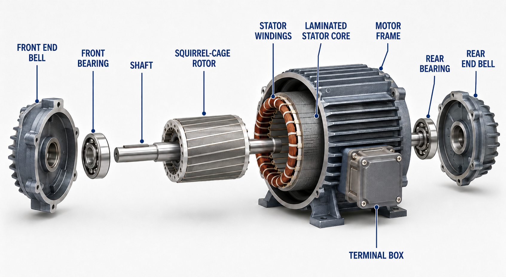
| Component | Function | Service Significance |
|---|---|---|
| Stator Windings | Carry current and establish the magnetic field required for motor operation. | Open, shorted, grounded, overheated, or incorrectly connected windings can prevent normal torque production. |
| Laminated Stator Core | Provides a magnetic path and supports the windings. Thin insulated laminations reduce circulating eddy-current losses. | Physical damage, overheating, or contact with the rotor can indicate a serious motor failure. |
| Rotor | Develops torque in response to the stator field and rotates within the stator. | Rotor damage, misalignment, or contact with the stator can cause noise, vibration, poor torque, or high current. |
| Shaft | Transfers motor torque to the driven load. | A bent shaft, damaged keyway, loose hub, or incorrect shaft dimensions can cause vibration and mechanical failure. |
| Bearings | Support the rotor and shaft while allowing low-friction rotation. | Worn, contaminated, dry, or misaligned bearings can produce noise, heat, drag, and excessive motor current. |
| Frame and End Bells | Protect, align, and support the motor components and provide mounting points. | Loose mounting, damaged end bells, or incorrect assembly can disturb alignment and increase vibration. |
| Air Gap | Provides the small physical clearance between the stator and rotor across which magnetic interaction occurs. | An uneven air gap may result from bearing wear, a bent shaft, poor alignment, or mechanical damage. |
Magnetic Fields Produce Torque
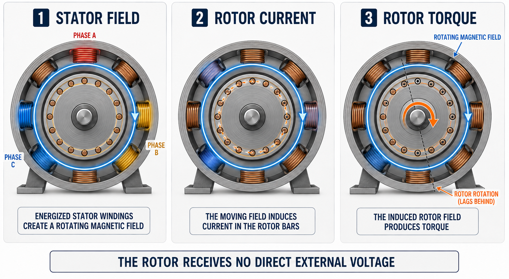
Current flowing through a conductor creates a magnetic field around that conductor. When current flows through the stator windings in the correct sequence, the combined magnetic field changes position around the stator. In a three-phase motor, the phase relationship of the three supply currents naturally produces a rotating magnetic field. Single-phase motors require an additional method of developing starting torque, which will be examined in later lessons.
As the stator field moves past the rotor conductors of a squirrel-cage induction motor, it induces voltage and current in those conductors. The induced rotor current creates a rotor magnetic field. Interaction between the stator and rotor fields produces torque and causes the rotor to follow the rotating stator field.
Current Enters the Stator
The applied voltage causes current to flow through the connected stator windings.
The Stator Field Moves
The arrangement of the windings and the timing of their currents create a magnetic field that changes position around the stator.
Rotor Current Is Induced
Relative motion between the stator field and rotor conductors induces voltage and current in the closed rotor circuit.
Torque Develops
The rotor magnetic field interacts with the stator field and produces turning force at the rotor and shaft.
Frequency and Number of Poles Set the Field Speed
The speed of the rotating stator field is called synchronous speed. It is determined by the supply frequency and the number of magnetic poles formed by the stator windings. Increasing frequency increases synchronous speed, while increasing the number of poles decreases synchronous speed.
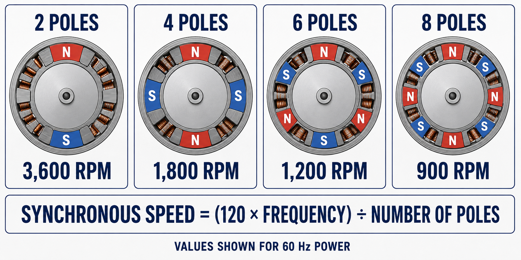
| Number of Poles | Synchronous Speed at 60 Hz | Common Induction-Motor Nameplate Range |
|---|---|---|
| 2 | 3600 RPM | Slightly below 3600 RPM |
| 4 | 1800 RPM | Slightly below 1800 RPM |
| 6 | 1200 RPM | Slightly below 1200 RPM |
| 8 | 900 RPM | Slightly below 900 RPM |
Example: Four-Pole Motor
For a four-pole motor supplied at 60 Hz, synchronous speed is (120 × 60) ÷ 4, or 1800 RPM.
Example: Six-Pole Motor
For a six-pole motor supplied at 60 Hz, synchronous speed is (120 × 60) ÷ 6, or 1200 RPM.
Do Not Confuse Field Speed With Shaft Speed
Synchronous speed is the speed of the rotating magnetic field. A loaded induction-motor rotor must operate below synchronous speed so that the field continues moving relative to the rotor conductors and inducing rotor current.
An Induction-Motor Rotor Runs Below Synchronous Speed
The difference between synchronous speed and actual rotor speed is called slip. If an induction-motor rotor reached the same speed as the stator field, there would be no relative motion between the field and rotor conductors, rotor induction would fall, and the motor could not continue producing the torque required by the load.
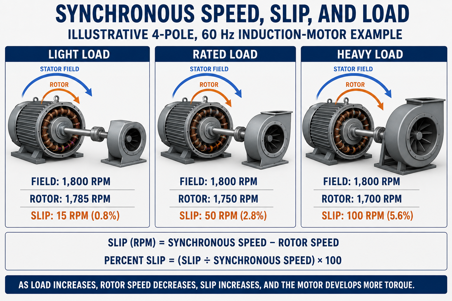
| Operating Condition | Synchronous Speed | Example Rotor Speed | Slip | Approximate Percent Slip |
|---|---|---|---|---|
| Light Load | 1800 RPM | 1785 RPM | 15 RPM | 0.8% |
| Rated Load | 1800 RPM | 1750 RPM | 50 RPM | 2.8% |
| Heavier Load | 1800 RPM | 1700 RPM | 100 RPM | 5.6% |
When the mechanical load increases, the rotor slows slightly. The resulting increase in relative motion produces greater rotor induction and allows the motor to develop more torque. This response is normal only within the motor’s intended operating range. If the required load torque exceeds the motor’s capability, speed may fall excessively, current and heating may rise, and the overload protection may open.
Worked Slip Example
A four-pole, 60-Hz motor has an 1800-RPM synchronous speed and operates at 1750 RPM. Its slip is 1800 − 1750 = 50 RPM. Percent slip is (50 ÷ 1800) × 100, or approximately 2.8%.
What Load Changes Do Not Change
For a motor connected to a fixed-frequency source, changing mechanical load does not change synchronous speed. It changes rotor speed and slip.
Construction and Speed Provide Diagnostic Clues
Nameplate RPM Suggests Pole Count
A 60-Hz induction motor rated slightly below 1800 RPM is commonly a four-pole motor, while one rated slightly below 3600 RPM is commonly a two-pole motor. Always confirm the actual rating from the nameplate and manufacturer information.
Bearings Affect Electrical Operation
Bearing drag increases the required shaft torque. The motor may slow, draw more current, run hotter, and eventually open its overload even though the original problem is mechanical.
Speed Affects Equipment Performance
Incorrect blower, fan, pump, or compressor speed can change airflow, fluid flow, refrigeration capacity, pressures, noise, energy use, and component temperature.
Frequency Control Changes Field Speed
A properly applied variable-frequency drive changes motor synchronous speed by changing output frequency. The motor, drive, equipment, and programmed limits must be compatible with the application.
Rotor or Air-Gap Problems Leave Clues
Abnormal noise, vibration, rubbing, repeated bearing failure, excessive current, or weak torque may indicate rotor, shaft, bearing, alignment, or air-gap problems.
The Driven Load Must Be Evaluated
A blocked blower, damaged fan blade, tight pump, failing compressor mechanism, or incorrect belt tension can overload a motor that is electrically intact.
Control Hazardous Energy Before Mechanical Inspection
A motor may start automatically and rotating parts may coast after power is removed. Follow the employer’s energy-control procedure, isolate all applicable energy sources, verify de-energization, control stored energy, and wait for moving parts to stop before touching the shaft, rotor, fan, blower, belt, coupling, or other driven components.
Avoid These Errors
“The Stator Rotates”
The stator is stationary. Its energized windings create a magnetic field that rotates or changes position around the stator.
“The Rotor Receives Line Voltage”
In a conventional squirrel-cage induction motor, the rotor is not wired to the external supply. Current is induced in its closed conductors by the moving stator field.
“Nameplate RPM Is Synchronous Speed”
The nameplate running speed of an induction motor is normally below synchronous speed because slip is required to develop torque.
“More Load Changes Synchronous Speed”
At a fixed supply frequency, more load causes the induction-motor rotor to slow and slip to increase. It does not change the synchronous speed of the stator field.
“Any Speed Loss Is Normal Slip”
Some slip is normal, but excessive speed loss may indicate overload, incorrect voltage, winding problems, mechanical drag, or another condition requiring diagnosis.
“All Motors Use the Same Rotor”
This lesson emphasizes squirrel-cage induction motors. ECMs and other permanent-magnet or electronically controlled motors use different rotor and control arrangements that are covered later in the section.
Review Questions
1. Which major part of a conventional induction motor remains stationary?
Answer: The stator remains stationary and contains the windings that establish the motor’s magnetic field.
2. What is the purpose of the air gap?
Answer: The air gap provides physical clearance for rotor movement while allowing magnetic interaction between the stator and rotor.
3. How does current enter a squirrel-cage rotor?
Answer: It is induced in the closed rotor conductors by relative motion between those conductors and the stator’s moving magnetic field.
4. What determines synchronous speed?
Answer: Synchronous speed is determined by supply frequency and the number of stator poles.
5. What is the synchronous speed of a four-pole motor supplied at 60 Hz?
Answer: (120 × 60) ÷ 4 = 1800 RPM.
6. A four-pole, 60-Hz motor operates at 1740 RPM. What are its slip RPM and approximate percent slip?
Answer: Slip is 1800 − 1740 = 60 RPM. Percent slip is (60 ÷ 1800) × 100, or approximately 3.3%.
7. Why must an induction-motor rotor operate below synchronous speed?
Answer: Relative motion between the stator field and rotor conductors is needed to induce rotor current and produce torque.
8. What normally happens to rotor speed and slip when mechanical load increases?
Answer: Rotor speed decreases slightly and slip increases, allowing the motor to develop additional torque within its designed operating range.
Lesson 2 Summary
- The stator is stationary, while the rotor and shaft turn to drive the connected load.
- Stator windings, a laminated core, rotor, shaft, bearings, frame, end bells, and air gap are major parts of a conventional induction motor.
- Current in the stator windings creates a magnetic field.
- A moving stator field induces current in the closed conductors of a squirrel-cage rotor.
- Interaction between stator and rotor magnetic fields produces torque.
- Synchronous speed is the speed of the stator’s rotating magnetic field.
- Synchronous speed equals 120 times frequency divided by the number of poles.
- At 60 Hz, common synchronous speeds are 3600 RPM for two poles, 1800 RPM for four poles, 1200 RPM for six poles, and 900 RPM for eight poles.
- An induction-motor rotor operates below synchronous speed because slip is required to induce rotor current and develop torque.
- At a fixed frequency, increasing mechanical load normally decreases rotor speed slightly and increases slip.
- Excessive load or mechanical drag can cause low speed, high current, overheating, and overload operation.
- Motor construction and speed information provide useful clues, but diagnosis must include the power supply, controls, motor, and driven load.