Introduction to Electric Motors in HVAC/R
Electric motors provide the mechanical motion needed to move refrigerant, circulate air, move water, and operate many of the components found in heating, air-conditioning, and refrigeration equipment. A technician may encounter several motor types in the same system, and each motor must be matched to the load it drives and the controls that operate it.
This lesson introduces the major jobs performed by motors in HVAC/R equipment, the motor families covered in this section, and the basic information a technician should gather before testing or replacing a motor. Later lessons examine motor construction, operation, connections, controls, and troubleshooting in greater detail.
Learning Objectives
Identify Motor Applications
Recognize the motors that drive compressors, indoor blowers, condenser fans, evaporator fans, pumps, and other HVAC/R loads.
Recognize Major Motor Families
Distinguish shaded-pole, PSC, capacitor-start, ECM, three-phase induction, and inverter-driven motor applications at an introductory level.
Relate the Motor to the Load
Understand that torque, speed, horsepower, direction of rotation, mounting, and control requirements are determined by the equipment application.
Begin With Safe Identification
Use the nameplate, wiring diagram, manufacturer information, and approved energy-control procedures before testing or replacing a motor.
Motors Convert Electrical Energy Into Mechanical Motion
An electric motor receives electrical energy and develops mechanical torque at its shaft or rotor. The motor does not perform useful HVAC/R work by itself. Useful work occurs when the motor drives a load such as a compressor mechanism, blower wheel, propeller fan, or pump impeller.
The motor and the driven load operate as a system. A motor can be electrically sound and still overheat or trip if the blower wheel is obstructed, a bearing is failing, a belt is too tight, a pump is mechanically bound, or the equipment is operating outside its intended conditions.
Where Motors Are Used in HVAC/R Equipment
A single HVAC/R system may contain several motors with very different jobs. Some start against high mechanical or refrigerant pressure loads, some operate small fans with very little starting torque, and others must vary speed in response to changing system demand.
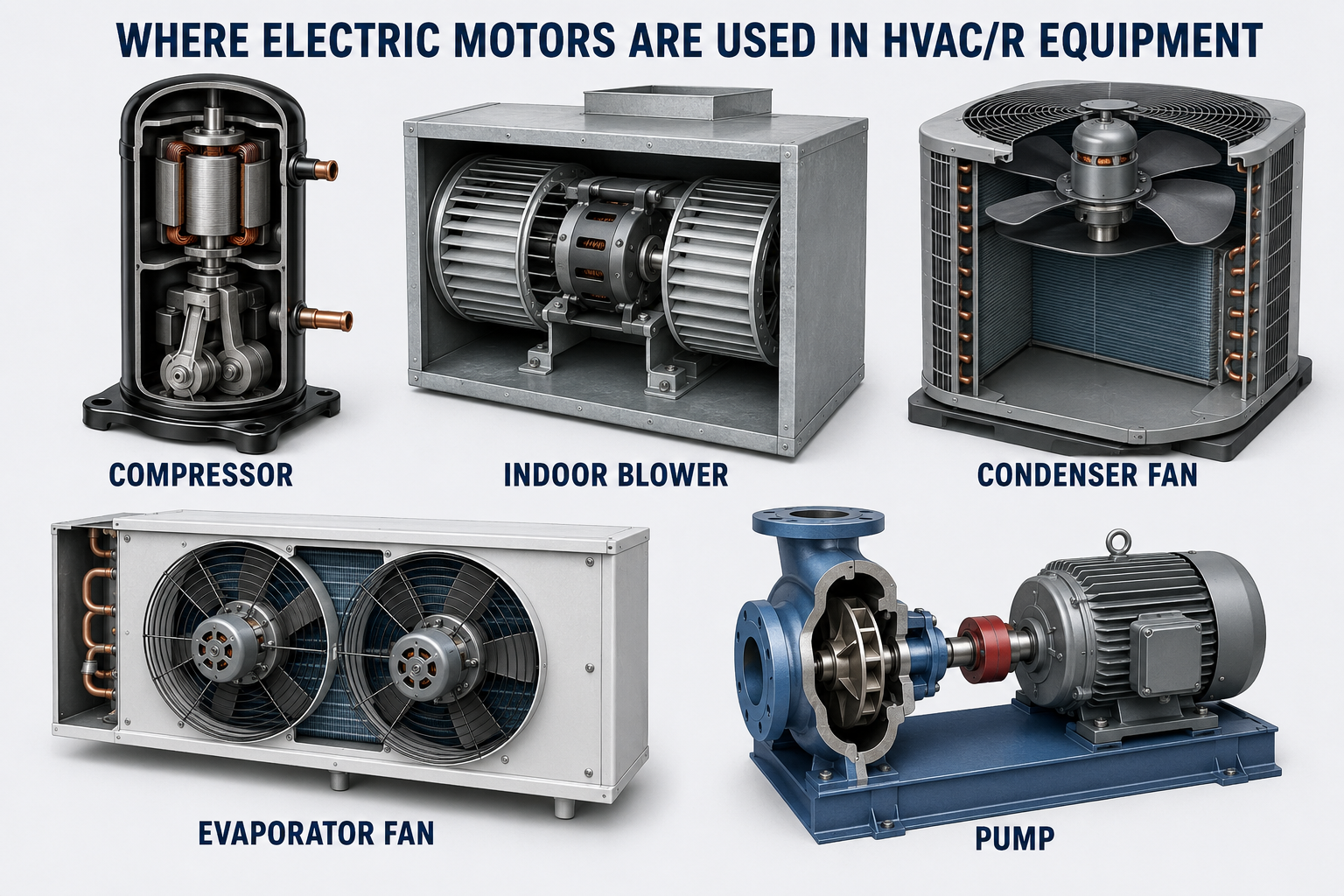
Compressor
The compressor motor drives the mechanism that raises refrigerant pressure and moves refrigerant through the system. Compressor motors may be single-phase, three-phase, or electronically driven depending on the equipment.
Indoor Blower
The indoor blower motor moves air across the indoor heat exchanger and through the building’s air-distribution system. Common examples include multi-speed PSC motors and electronically commutated motors.
Condenser Fan
The condenser fan motor moves outdoor air across an air-cooled condenser coil. The correct motor must match the fan blade, required airflow, direction of rotation, mounting, and equipment operating conditions.
Evaporator Fan
Evaporator fan motors circulate air across refrigeration evaporators and through refrigerated spaces. Small shaded-pole or PSC motors have traditionally been common, while higher-efficiency electronic motors are also used.
Pumps
Pump motors circulate chilled water, condenser water, heating water, and condensate. The motor must be matched to the pump load, supply, enclosure, mounting, and control method.
Other Motor-Driven Loads
HVAC/R equipment may also use motors for cooling towers, exhaust fans, combustion-air blowers, draft inducers, dampers, valves, and specialized material or air-handling equipment.
The Application Determines What the Motor Must Do
A motor must develop enough starting torque to begin moving the load and enough running torque to keep the load operating. The mechanical characteristics of a small fan are different from those of a compressor, pump, or large blower, so a motor that works correctly in one application may be unsuitable in another.
| Application Requirement | Why It Matters | What the Technician Should Confirm |
|---|---|---|
| Starting Torque | The motor must accelerate the connected load from rest. | Motor type, start components, supply voltage, load condition, and manufacturer application. |
| Running Torque and Horsepower | The motor must continue driving the load without exceeding its rating. | Nameplate horsepower, full-load current, service factor where applicable, and actual mechanical load. |
| Speed | Motor speed affects blower airflow, fan performance, pump flow, compressor capacity, and equipment operation. | Rated RPM, number of speeds, speed tap or command, pulley arrangement, and approved speed-control method. |
| Direction of Rotation | Incorrect rotation can sharply reduce performance and may damage some driven equipment. | Required rotation viewed from the specified end, wiring diagram, fan or pump direction, and post-service rotation check. |
| Duty and Environment | Temperature, moisture, contamination, airflow, and operating time affect motor life. | Duty rating, enclosure, ambient rating, insulation class, cooling method, and mounting location. |
| Control Method | The motor must be compatible with the equipment’s relays, speed taps, electronic signals, inverter, or variable-frequency drive. | Wiring diagram, supply type, control voltage or signal, approved drive, and manufacturer programming requirements. |
Do Not Select a Replacement by Horsepower Alone
A replacement motor must match the application and the equipment requirements. Voltage, phase, frequency, horsepower, speed, rotation, frame, shaft, mounting, capacitor requirements, duty, enclosure, ambient conditions, and control method may all affect whether the replacement is suitable.
HVAC/R Equipment Uses Several Motor Designs
Motor construction and control vary with equipment size, torque requirements, efficiency goals, available electrical power, and the need for speed control. The following overview introduces the motor families examined later in this section.
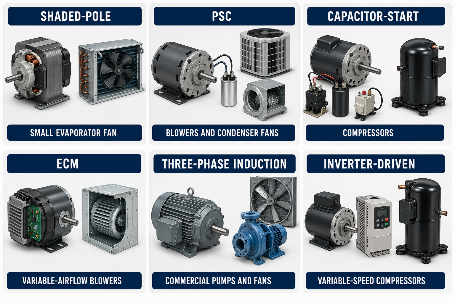
Shaded-Pole Motors
Shaded-pole motors are simple single-phase motors used for some small, low-torque fan applications. They do not use a start or run capacitor and generally have low starting torque and relatively low efficiency.
PSC Motors
A permanent split capacitor motor uses a run winding, an auxiliary winding, and a run capacitor that remains in the circuit during operation. PSC motors have been widely used for blowers, condenser fans, evaporator fans, and pumps.
Capacitor-Start Motors
Capacitor-start motors use additional starting components to develop higher starting torque. CSIR and CSCR arrangements are commonly associated with single-phase compressors and other loads that require stronger starting performance.
ECMs
An electronically commutated motor uses a permanent-magnet rotor, a wound stator, and electronic controls to commutate the stator windings. ECM applications can provide fixed, multi-speed, constant-torque, variable-speed, or airflow-control operation depending on the design.
Three-Phase Induction Motors
Three-phase induction motors use the three-phase supply to create a rotating magnetic field. They are common in commercial compressors, pumps, fans, cooling towers, and air-handling equipment.
Inverter- and VFD-Driven Motors
Approved motors and compressors can be operated by electronic drives that vary output frequency and voltage. These systems allow motor speed or compressor capacity to respond to changing load.
The Available Power Supply Influences Motor Design
Smaller residential and light-commercial equipment commonly uses single-phase power, while larger commercial and industrial equipment often has three-phase power available. This general pattern is useful, but equipment must always be identified from its nameplate and wiring information rather than from size or appearance alone.
Single-Phase Motors
A single-phase induction motor requires a method of creating the phase displacement needed to establish starting torque. Depending on the design, that method may use a shaded pole, auxiliary winding, capacitor, relay, centrifugal switch, or electronic control.
Three-Phase Motors
A balanced three-phase supply naturally produces a rotating magnetic field in the stator. Conventional three-phase induction motors therefore do not require the starting winding and capacitor arrangements used by many single-phase motors.
Electronically Produced Three-Phase Power
An ECM, inverter, or VFD can electronically create controlled three-phase power for a compatible motor even when the equipment receives a different form of incoming power.
Confirm Before Testing
The test procedure depends on the motor and control design. A procedure suitable for a conventional PSC motor may damage an ECM module or produce misleading results on inverter-driven equipment.
Begin With the Nameplate, Diagram, and Equipment Information
Before disconnecting wires or taking electrical measurements, identify the motor and document how it is connected. Photographs, wire labels, terminal markings, the equipment schematic, and the motor connection diagram can prevent wiring errors during reassembly.
Identify the Driven Load
Determine whether the motor drives a compressor, blower, propeller fan, pump, or another load and observe the required direction of rotation.
Read the Nameplate
Record voltage, phase, frequency, horsepower, current, RPM, duty, service factor where listed, capacitor information, and other ratings provided by the manufacturer.
Locate the Wiring Diagram
Use the motor and equipment diagrams to identify supply connections, speed leads, capacitor connections, overloads, relays, electronic controls, and unused leads.
Inspect the Mechanical Load
With hazardous energy controlled, check for binding, damaged bearings, obstruction, contamination, improper belt tension, or other conditions that can overload the motor.
Document the Connections
Label wires and record their original positions before removal. Do not rely on wire color alone because colors and connector arrangements vary by manufacturer.
Select the Correct Test
Choose measurements that are appropriate for the motor and control system, and isolate electronic modules before applying tests that could damage them.
Motors Can Start Without Warning
HVAC/R motors may be started automatically by thermostats, pressure controls, electronic control boards, timers, building automation systems, or remote commands. Opening a control circuit or turning a thermostat off is not necessarily the same as isolating the equipment from hazardous energy.
Control Hazardous Energy Before Service
Follow the employer’s energy-control procedure and all applicable safety requirements. Shut down and isolate the equipment, apply lockout/tagout as required, control stored or residual energy, discharge capacitors using an approved procedure when applicable, and verify isolation and de-energization before contacting conductors or moving parts.
Electrical Energy
Line voltage, control voltage, capacitors, and electronic DC buses can remain hazardous. Use properly rated instruments and procedures appropriate to the equipment.
Unexpected Motion
Fan blades, blower wheels, belts, shafts, and pump couplings can start or coast unexpectedly. Replace guards and covers before returning equipment to service.
Automatic Controls
Thermostats and control boards can restart equipment when conditions change. A control command should never be treated as the sole means of energy isolation.
Qualified Work
Energized measurements expose the technician to additional hazards and should be performed only by qualified persons using approved procedures, appropriate PPE, and properly rated test equipment.
Avoid These Early Motor-Diagnosis Errors
“The Motor Is Hot, So It Is Bad”
Motor temperature alone does not identify the cause. Excessive load, poor cooling, low or unbalanced voltage, incorrect connections, frequent starting, bearing problems, or a motor fault may all contribute.
“The Same Horsepower Means It Will Fit”
Horsepower is only one replacement requirement. Electrical ratings, speed, rotation, frame, shaft, mounting, duty, capacitor, control method, and environmental ratings must also be suitable.
“Wire Colors Are Universal”
Manufacturers may use different colors and connector arrangements. Identify leads from the applicable motor diagram, equipment diagram, terminal markings, and approved test procedures.
“All Blower Motors Are PSC Motors”
Many systems use PSC motors, but ECMs and other electronically controlled motors are also common. Testing and replacement procedures must match the actual motor design.
“A Motor Problem Is Always Electrical”
A mechanically overloaded blower, fan, compressor, or pump can cause high current, low speed, overheating, and overload trips even when the motor windings are not the original cause.
“Turning Off the Thermostat Makes It Safe”
A thermostat interrupts or changes a control command; it is not normally an energy-isolating device. Use the required disconnecting and energy-control procedures.
Review Questions
1. What basic energy conversion takes place in an electric motor?
Answer: The motor converts electrical energy into mechanical torque and motion that can drive a connected load.
2. Name five common motor-driven HVAC/R loads.
Answer: Examples include compressors, indoor blowers, condenser fans, evaporator fans, and pumps.
3. Why must the mechanical load be checked when troubleshooting a motor?
Answer: Binding, obstruction, bearing problems, belt problems, incorrect airflow or fluid conditions, and other mechanical issues can overload an electrically sound motor.
4. Which motor family uses a run capacitor that remains in the circuit during operation?
Answer: A permanent split capacitor, or PSC, motor.
5. Which common motor family uses a permanent-magnet rotor and integrated electronic commutation?
Answer: An electronically commutated motor, or ECM.
6. Why should a replacement motor not be selected by horsepower alone?
Answer: The replacement must also match the required voltage, phase, frequency, current, speed, rotation, frame, shaft, mounting, duty, capacitor requirements, environmental rating, and control method.
7. Why should wire color not be used as the only method of identifying motor leads?
Answer: Wire colors and connector arrangements vary among manufacturers. The applicable wiring diagram, nameplate, terminal markings, and approved tests should be used.
8. Why is turning off a thermostat not sufficient energy isolation for motor service?
Answer: The thermostat normally changes only a control command. Line voltage, stored energy, other control signals, or automatic commands may still be present, so the required energy-control procedure must be followed.
Lesson 1 Summary
- Electric motors convert electrical energy into mechanical torque and motion.
- HVAC/R motors drive compressors, blowers, condenser fans, evaporator fans, pumps, and many other loads.
- The motor and driven load operate as a system, so electrical and mechanical conditions must both be evaluated.
- Starting torque, running torque, horsepower, speed, rotation, duty, environment, and control method are determined by the application.
- Major HVAC/R motor families include shaded-pole, PSC, capacitor-start, ECM, three-phase induction, and inverter- or VFD-driven motors.
- A PSC motor uses a run capacitor that remains connected during operation.
- An ECM uses electronic commutation and a permanent-magnet rotor.
- A conventional three-phase induction motor uses a three-phase stator field and a squirrel-cage rotor.
- Typical applications are clues, but the nameplate, wiring diagram, and manufacturer information must identify the actual motor.
- A replacement motor must be matched to more than horsepower.
- Wire colors and connector arrangements are not universal.
- Automatic controls can start motors unexpectedly, so approved hazardous-energy control procedures must be followed before service.