Back to: NASCLA Master Electrical Contractor Exam Preparation
Electrical circuits may contain components connected in series, in parallel, or in combinations of both arrangements. The way components are connected determines how current flows, how voltage is distributed, and how total resistance is calculated.
For NASCLA examination preparation, you should be able to recognize each circuit configuration, apply Ohm’s Law to the correct portion of the circuit, calculate equivalent resistance, determine circuit and branch currents, calculate voltage drops, and verify your answers using the electrical relationships developed in the previous lessons.
How Circuit Configuration Changes Electrical Behavior
Ohm’s Law does not change when resistors are connected in different arrangements, but the voltage, current, and resistance values used in the equation must describe the same component or the same portion of the circuit.
In a series circuit, current has only one path and therefore passes through each series component. In a parallel circuit, components are connected across the same two nodes, so they have the same voltage while current divides among the branches. Combination circuits contain both arrangements and are solved by reducing the circuit one section at a time.
The key to solving these circuits is identifying the configuration before beginning the arithmetic.
One Path for Current
A series circuit provides only one path for current. Because there are no junctions at which current can divide, the same current passes through every component connected in series.
Current
The current is the same through every series component.
IT = I1 = I2 = …
Voltage
The source voltage equals the sum of the individual voltage drops.
VT = V1 + V2 + …
Resistance
Series resistances add directly.
RT = R1 + R2 + …
Calculate the Circuit One Step at a Time
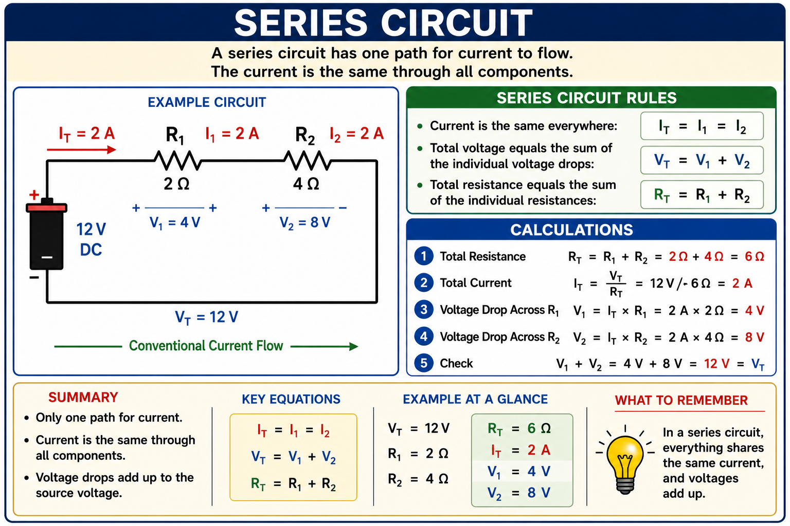
The example contains a 12-volt source with a 2-ohm resistor and a 4-ohm resistor connected in series.
Calculate Total Resistance
RT = R1 + R2
RT = 2 Ω + 4 Ω = 6 Ω
Calculate Total Current
IT = VT ÷ RT
IT = 12 V ÷ 6 Ω = 2 A
Calculate the Voltage Across R1
V1 = I × R1
V1 = 2 A × 2 Ω = 4 V
Calculate the Voltage Across R2
V2 = I × R2
V2 = 2 A × 4 Ω = 8 V
Check the Voltage Drops
VT = V1 + V2
12 V = 4 V + 8 V
Total Resistance Must Increase
Adding another resistance in series increases total circuit resistance. The total resistance of a series circuit must therefore be greater than any individual resistance in that series string.
If your calculation produces a total resistance smaller than one of the individual series resistances, recheck the calculation.
Series Resistance Determines Voltage Drop
Because the same current passes through every resistor in a series circuit, the voltage drop across each resistor depends on its resistance. A larger resistance produces a larger voltage drop when the same current passes through it.
In the example circuit, R2 is twice the resistance of R1. Its 8-volt drop is therefore twice the 4-volt drop across R1.
Same current + greater resistance = greater voltage drop.
Multiple Paths for Current
Components are in parallel when they are connected between the same two electrical nodes. Each parallel branch therefore has the same voltage across it.
Unlike a series circuit, current can divide at a junction. Total current entering a junction equals the sum of the currents through the individual branches.
Voltage
Voltage is the same across every parallel branch.
VT = V1 = V2 = …
Current
Total current equals the sum of the branch currents.
IT = I1 + I2 + …
Resistance
Parallel resistance is calculated using reciprocal relationships.
1/RT = 1/R1 + 1/R2 + …
Voltage Is Shared Across the Branches
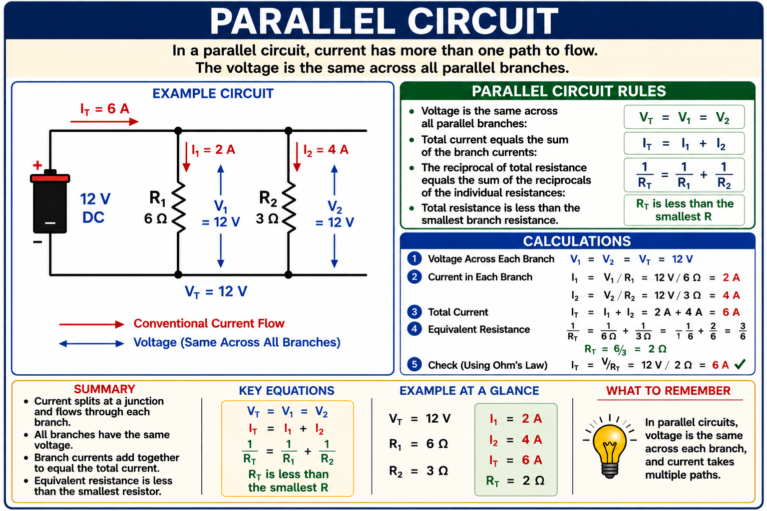
The example contains a 12-volt source with a 6-ohm resistor and a 3-ohm resistor connected in parallel.
Determine Branch Voltage
Both resistors are connected across the same two nodes.
V1 = V2 = VT = 12 V
Calculate Current Through R1
I1 = V1 ÷ R1
I1 = 12 V ÷ 6 Ω = 2 A
Calculate Current Through R2
I2 = V2 ÷ R2
I2 = 12 V ÷ 3 Ω = 4 A
Calculate Total Current
IT = I1 + I2
IT = 2 A + 4 A = 6 A
Calculate Equivalent Resistance
1/RT = 1/6 Ω + 1/3 Ω
1/RT = 1/6 + 2/6 = 3/6
RT = 2 Ω
Check With Ohm’s Law
IT = VT ÷ RT
IT = 12 V ÷ 2 Ω = 6 A
Equivalent Resistance Must Be Less Than the Smallest Branch Resistance
Adding another parallel current path reduces the equivalent resistance seen by the source. For resistors connected in parallel, the equivalent resistance must therefore be less than the smallest individual branch resistance.
In the example, the smallest branch resistance is 3 ohms and the equivalent resistance is 2 ohms. That relationship provides a quick check on the calculation.
A Faster Method for Two Parallel Resistors
When exactly two resistors are connected in parallel, their equivalent resistance can also be calculated using the product-over-sum relationship.
RT = (R1 × R2) ÷ (R1 + R2)
For the 6-ohm and 3-ohm branches:
RT = (6 Ω × 3 Ω) ÷ (6 Ω + 3 Ω)
RT = 18 ÷ 9 = 2 Ω
This shortcut produces the same result as the reciprocal formula, but it applies directly only to two parallel resistances at a time.
Lower Resistance Carries More Current
Each parallel branch has the same voltage, so Ohm’s Law determines how much current flows through each branch. A branch with lower resistance carries more current than a branch with higher resistance when both have the same applied voltage.
In the example, the 3-ohm branch carries 4 amperes while the 6-ohm branch carries 2 amperes. Cutting the resistance in half doubles the current when voltage remains constant.
Same voltage + lower resistance = greater branch current.
Current Into a Junction Equals Current Out
The current relationship used in a parallel circuit is an application of Kirchhoff’s Current Law. At a circuit junction, the algebraic sum of currents is zero. In practical terms, the total current entering a junction equals the total current leaving it.
For the example circuit, 6 amperes reaches the junction. The current divides into 2 amperes through one branch and 4 amperes through the other branch.
6 A = 2 A + 4 A
When the branches rejoin, the two branch currents combine again to form the 6-ampere total circuit current.
Voltage Changes Around a Closed Loop Balance
Kirchhoff’s Voltage Law states that the algebraic sum of the voltage changes around a closed circuit loop is zero. In a simple series circuit, this means the individual voltage drops add to the applied source voltage.
For the series example:
12 V = 4 V + 8 V
This provides another useful way to verify circuit calculations.
Series and Parallel Sections in the Same Circuit
A combination circuit contains both series and parallel portions. These circuits may initially appear more complicated, but the same fundamental relationships still apply.
The most reliable method is to identify a section that is clearly series or parallel, calculate its equivalent resistance, replace that section with the equivalent resistance, and repeat the process until the circuit has been reduced to a simple equivalent circuit.
Reduce the Circuit Before Solving It
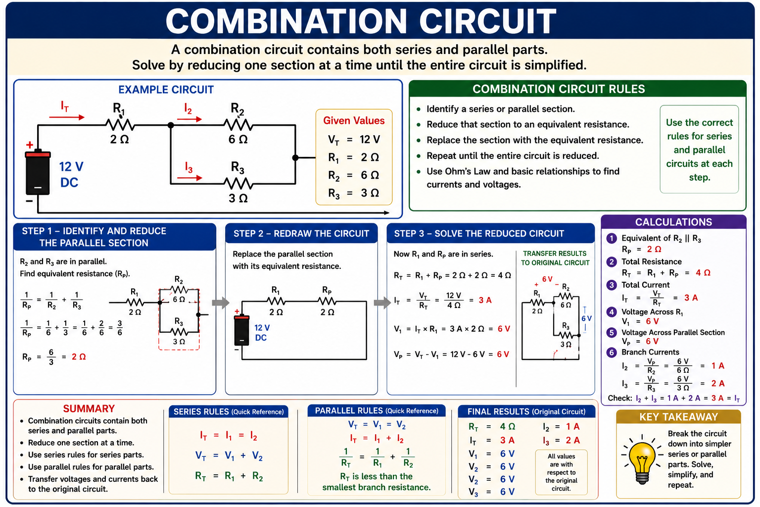
The example contains R1 = 2 Ω in series with a parallel network consisting of R2 = 6 Ω and R3 = 3 Ω. The source voltage is 12 volts.
Reduce the Parallel Section
R2 and R3 are connected across the same two nodes, so they are in parallel.
1/RP = 1/R2 + 1/R3
1/RP = 1/6 + 1/3
1/RP = 1/6 + 2/6 = 3/6
RP = 2 Ω
The two parallel resistors can now be represented by one equivalent 2-ohm resistance.
Calculate Total Circuit Resistance
After the parallel section is reduced, the equivalent 2-ohm resistance is in series with R1, which is also 2 ohms.
RT = R1 + RP
RT = 2 Ω + 2 Ω = 4 Ω
Calculate Total Current
Once total resistance is known, apply Ohm’s Law to the complete circuit.
IT = VT ÷ RT
IT = 12 V ÷ 4 Ω = 3 A
The 3-ampere total current passes through R1 before reaching the junction where it divides between R2 and R3.
Determine the Voltage Across R1
R1 carries the full 3-ampere circuit current because it is in series with the entire parallel network.
V1 = IT × R1
V1 = 3 A × 2 Ω = 6 V
Determine the Voltage Across the Parallel Network
The source supplies 12 volts and R1 drops 6 volts. The remaining voltage must appear across the parallel section.
VP = VT − V1
VP = 12 V − 6 V = 6 V
Because R2 and R3 are parallel, each resistor has 6 volts across it.
Calculate the Branch Currents
With the parallel-section voltage known, apply Ohm’s Law separately to each branch.
R2 Branch
I2 = V2 ÷ R2
I2 = 6 V ÷ 6 Ω
I2 = 1 A
R3 Branch
I3 = V3 ÷ R3
I3 = 6 V ÷ 3 Ω
I3 = 2 A
The branch currents should add to the total current:
IT = I2 + I3
3 A = 1 A + 2 A
Keep Voltage, Current, and Resistance From the Same Part of the Circuit
Ohm’s Law relates the voltage across a component or circuit section, the current through that same component or section, and its resistance. Values from unrelated portions of a combination circuit cannot be mixed arbitrarily.
For example, the 6-ohm R2 branch has 6 volts across it and carries 1 ampere. Using the total 12-volt source voltage with the 6-ohm branch resistance would incorrectly produce 2 amperes because R2 does not have the entire 12 volts across it in this combination circuit.
How to Solve Combination Circuits
Identify the Circuit Structure
Locate components that are clearly in series and components that share the same two nodes and are therefore in parallel.
Reduce One Section
Calculate the equivalent resistance of an identifiable series or parallel section.
Redraw Mentally or on Scratch Paper
Replace the reduced section with its equivalent resistance. This makes the remaining circuit easier to analyze.
Repeat as Necessary
Continue reducing the circuit until total resistance can be determined.
Calculate Total Current
Use the source voltage and total equivalent resistance to determine the current supplied by the source.
Work Back Into the Original Circuit
Determine voltage drops and branch currents using the rules that apply to each original series or parallel section.
Verify the Results
Check that series voltage drops add correctly, parallel branch currents add correctly, and all Ohm’s Law relationships are internally consistent.
Know Which Quantity Stays the Same
Series
Current stays the same.
Voltage divides among components.
Resistance adds directly.
Parallel
Voltage stays the same.
Current divides among branches.
Equivalent resistance decreases as parallel paths are added.
Quick memory aid: Series — same current. Parallel — same voltage.
Avoid These Circuit-Calculation Mistakes
Adding Parallel Resistances Directly
Direct addition applies to series resistances, not to resistances connected in parallel.
Dividing Voltage in Parallel
Parallel branches connected across the same two nodes have the same voltage.
Using the Same Current in Every Parallel Branch
Branch current depends on branch resistance. Only the sum of the branch currents equals total current.
Assuming Source Voltage Appears Across Every Component
That is true for components directly connected across the same source nodes, but not for every component in a combination circuit.
Mixing Circuit Values
Use voltage, current, and resistance values that describe the same component or equivalent circuit section.
Skipping the Final Check
Kirchhoff’s voltage and current relationships provide valuable checks on calculated answers.
Identify the Circuit Before Reaching for the Calculator
When a circuit calculation appears on the examination, first determine whether the components are in series, parallel, or a combination. Do not choose a resistance formula merely because resistance values appear in the question.
Look for junctions, common nodes, and the available current paths. Once the circuit configuration is identified correctly, the required calculations usually become much more straightforward.
Check Your Understanding
Series Resistance
Three resistors of 4 Ω, 6 Ω, and 10 Ω are connected in series. What is the total resistance?
A. 2 Ω
B. 10 Ω
C. 20 Ω
D. 240 Ω
Series Current
A 24-volt source is connected to a series circuit having a total resistance of 12 Ω. What current flows through each component?
A. 0.5 A
B. 2 A
C. 12 A
D. 288 A
Parallel Voltage
Three resistors are connected in parallel across a 120-volt source. What voltage appears across each branch?
A. 40 V
B. 60 V
C. 120 V
D. The voltage depends only on branch resistance.
Parallel Resistance
Two 12-ohm resistors are connected in parallel. What is their equivalent resistance?
A. 6 Ω
B. 12 Ω
C. 24 Ω
D. 144 Ω
Branch Current
A 24-ohm resistor is connected directly across a 120-volt source as one branch of a parallel circuit. What current flows through that branch?
A. 0.2 A
B. 5 A
C. 24 A
D. 2,880 A
Combination Circuit
A 4-ohm resistor is in series with two 12-ohm resistors connected in parallel. What is the total circuit resistance?
A. 6 Ω
B. 10 Ω
C. 16 Ω
D. 28 Ω
Review the Reasoning
Question 1 — C
Series resistances add directly: 4 Ω + 6 Ω + 10 Ω = 20 Ω.
Question 2 — B
I = V ÷ R = 24 V ÷ 12 Ω = 2 A. Because the components are in series, the same 2 amperes flows through each component.
Question 3 — C
Each parallel branch is connected across the same two nodes as the source, so each branch has 120 volts across it.
Question 4 — A
Two equal 12-ohm resistors in parallel have an equivalent resistance of 6 ohms. Using product over sum: (12 × 12) ÷ (12 + 12) = 144 ÷ 24 = 6 Ω.
Question 5 — B
Use Ohm’s Law for that branch: I = 120 V ÷ 24 Ω = 5 A.
Question 6 — B
The two equal 12-ohm parallel resistors reduce to 6 ohms. That equivalent resistance is in series with the 4-ohm resistor, so RT = 4 Ω + 6 Ω = 10 Ω.
What You Should Take From This Lesson
Series Circuits Have One Current Path
The same current flows through all series components, resistances add directly, and individual voltage drops add to the source voltage.
Parallel Circuits Have Multiple Paths
Parallel branches have the same voltage, while total current equals the sum of the individual branch currents.
Parallel Resistance Is Less Than the Smallest Branch
Adding parallel paths reduces the equivalent resistance seen by the source.
Combination Circuits Are Reduced in Sections
Identify a series or parallel section, calculate its equivalent resistance, simplify the circuit, and repeat.
Work Back Into the Original Circuit
After determining total resistance and total current, calculate the voltage and current associated with each original component or branch.
Keep Ohm’s Law Values Together
The voltage, current, and resistance used in an Ohm’s Law calculation must describe the same component or circuit section.
Verify the Answer
Use voltage sums, current sums, equivalent-resistance relationships, and Ohm’s Law to check whether the calculated values make electrical sense.
Leave a Reply
You must be logged in to post a comment.