Back to: NASCLA Master Electrical Contractor Exam Preparation
Alternating-current systems introduce relationships that do not appear in simple DC circuits. Electrical contractors preparing for the NASCLA exam should be comfortable with AC frequency, period, peak and RMS values, phase relationships, real power, reactive power, apparent power, and power factor.
This lesson develops the AC concepts needed for the single-phase, three-phase, transformer, motor, voltage-drop, and load-calculation lessons that follow. The emphasis is recognizing the relationships, selecting the correct formula, and understanding what the calculated values represent.
Alternating Current Requires a Different Way of Looking at Voltage, Current, and Power
In a DC circuit, voltage and current can often be treated as steady values. In an AC circuit, instantaneous voltage and current vary continuously, and they may not reach their maximum values at the same time.
Understanding frequency, RMS values, phase angle, and power factor allows the electrician to interpret AC measurements and solve the power calculations encountered in motors, transformers, feeders, branch circuits, and other electrical systems.
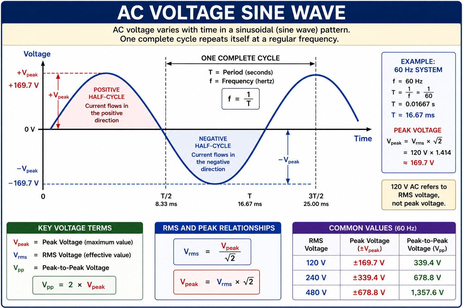
AC Voltage Changes Magnitude and Polarity
Direct-current voltage maintains the same polarity. Alternating-current voltage periodically changes polarity and usually changes magnitude throughout each cycle.
Utility electrical power is AC. The sinusoidal waveform is the basic model used to describe voltage and current in conventional AC power systems.
Direct Current
DC voltage maintains one polarity. Batteries, DC power supplies, and many electronic circuits operate with direct current.
Alternating Current
AC voltage repeatedly changes polarity. Utility distribution systems use alternating current because AC voltage can be readily transformed to different voltage levels.
Instantaneous Value
The voltage or current at a particular point in time is its instantaneous value. That value continuously changes throughout a sinusoidal cycle.
Complete Cycle
One complete AC cycle includes a positive half-cycle and a negative half-cycle before the waveform begins repeating.
Frequency Tells How Often the Waveform Repeats
Frequency describes the number of complete AC cycles that occur each second. Frequency is measured in hertz, abbreviated Hz. One hertz equals one cycle per second.
Period describes the amount of time required for one complete cycle. Frequency and period are reciprocals of one another.
Frequency and Period
f = 1 / T
T = 1 / f
Where f is frequency in hertz and T is period in seconds.
Start With Frequency
A standard 60 Hz system completes 60 electrical cycles every second.
Calculate Period
T = 1 / f = 1 / 60 = 0.01667 second.
Convert to Milliseconds
0.01667 second × 1000 = approximately 16.67 milliseconds.
Exam point: A 60 Hz waveform completes one full electrical cycle approximately every 16.67 milliseconds.
AC Voltage Is Normally Stated as an RMS Value
Because a sinusoidal voltage is constantly changing, its instantaneous value is not suitable as a single operating value. Electrical systems therefore commonly use the root-mean-square value, abbreviated RMS.
For a resistive load, an RMS AC value produces the same average heating effect as the equivalent DC value. Common system voltages such as 120 V, 208 V, 240 V, and 480 V are normally stated as RMS voltages.
Peak Voltage
The peak voltage is the maximum instantaneous magnitude reached by the sinusoidal waveform.
RMS Voltage
The RMS voltage is the effective AC voltage used in most practical electrical calculations and equipment ratings.
Convert Between RMS and Peak Values
VRMS = Vpeak / √2
Vpeak = VRMS × √2
IRMS = Ipeak / √2
Ipeak = IRMS × √2
Determine Peak Voltage From a 120 V RMS Source
A sinusoidal AC source is rated at 120 V RMS. Determine the approximate peak voltage.
Identify the Known Value
VRMS = 120 V.
Select the Formula
Vpeak = VRMS × √2.
Calculate
Vpeak = 120 × 1.414 = approximately 169.7 V.
Answer: A 120 V RMS sinusoidal source reaches a peak magnitude of approximately 169.7 V.
Voltage and Current May Not Reach Their Peaks Together
Voltage and current in an AC circuit may be in phase or separated by a phase angle. The phase angle is commonly represented by the Greek letter φ.
The relationship depends on the electrical characteristics of the load. Resistance, inductance, and capacitance affect the timing relationship between voltage and current.
Resistive Load
In an ideal resistive circuit, voltage and current are in phase. Their zero crossings and peaks occur at the same time.
Inductive Load
In an ideal inductive circuit, current lags voltage. Motors, transformers, and other magnetic devices introduce inductive characteristics.
Capacitive Load
In an ideal capacitive circuit, current leads voltage. Capacitors therefore influence the phase relationship between current and voltage.
Memory aid: In an inductive circuit, current lags voltage. In a capacitive circuit, current leads voltage.
Real, Reactive, and Apparent Power Describe Different Parts of the Load
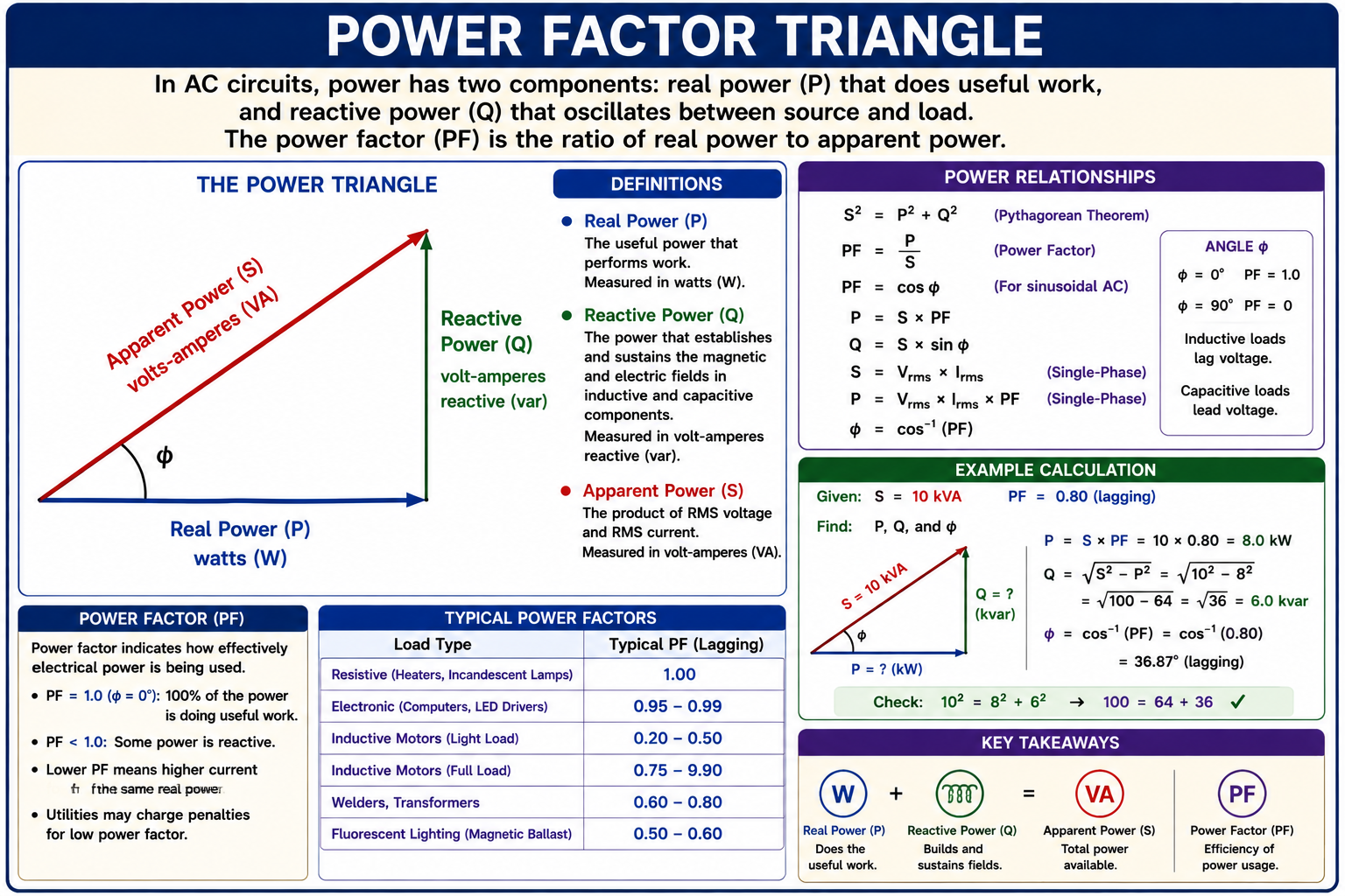
When voltage and current are not in phase, multiplying RMS voltage by RMS current gives apparent power rather than real power. AC power calculations therefore distinguish real power, reactive power, and apparent power.
Real Power — P
Real power is the average power converted into useful work, heat, light, or mechanical output. Real power is measured in watts.
Reactive Power — Q
Reactive power represents energy exchanged between the source and magnetic or electric fields. Reactive power is measured in volt-amperes reactive, abbreviated var.
Apparent Power — S
Apparent power is the product of RMS voltage and RMS current before power factor is applied. Apparent power is measured in volt-amperes.
Basic Single-Phase Sinusoidal AC Power Formulas
S = VRMS × IRMS
P = VRMS × IRMS × PF
S² = P² + Q²
S = √(P² + Q²)
Power Factor Compares Real Power With Apparent Power
Power factor is the ratio of real power to apparent power. It describes how much of the apparent power supplied to the load is represented by real power.
Power factor has no unit. A power factor of 1.0 means that real power and apparent power are numerically equal.
Power Factor Relationships
PF = P / S
For sinusoidal voltage and current:
PF = cos φ
Therefore:
P = S × PF
Exam point: If a single-phase problem gives voltage, current, and power factor and asks for real power, use P = V × I × PF. If it asks for apparent power, use S = V × I.
Calculate Apparent, Real, and Reactive Power
A single-phase load operates at 240 V, draws 20 A, and has a power factor of 0.80. Determine its apparent power, real power, and reactive power.
Calculate Apparent Power
S = V × I = 240 V × 20 A = 4,800 VA, or 4.8 kVA.
Calculate Real Power
P = S × PF = 4,800 × 0.80 = 3,840 W, or 3.84 kW.
Calculate Reactive Power
Q = √(S² − P²) = √(4,800² − 3,840²) = 2,880 var, or 2.88 kvar.
Results: Apparent power = 4.8 kVA, real power = 3.84 kW, reactive power = 2.88 kvar, and power factor = 0.80.
Lower Power Factor Requires More Current for the Same Real Power
For a given amount of real power at a fixed voltage, current increases as power factor decreases. This additional current can increase conductor losses, voltage drop, and the required capacity of electrical equipment.
4.8 kW at PF = 1.00
I = P / (V × PF) = 4,800 / (240 × 1.00) = 20 A.
4.8 kW at PF = 0.80
I = P / (V × PF) = 4,800 / (240 × 0.80) = 25 A.
Comparison: Both loads use 4.8 kW of real power, but the 0.80 power-factor load requires 5 A more current from the same 240 V source.
Identify Which Type of Power the Question Is Asking For
Read the units carefully. Watts or kilowatts indicate real power, volt-amperes or kilovolt-amperes indicate apparent power, and var or kvar indicate reactive power.
If power factor is supplied, determine whether it belongs in the formula before calculating. A common error is to multiply volts by amps and report the result in watts even though the load has a power factor less than 1.0.
Watch for These Mistakes
Using Peak Instead of RMS
Common AC system voltages and currents are normally RMS values unless the problem specifically states peak or another type of value.
Forgetting Power Factor
When calculating real power for a sinusoidal AC load with a stated power factor, include the power factor in the calculation.
Confusing VA With Watts
Volt-amperes describe apparent power. Watts describe real power. They are equal only when the power factor is 1.0.
Mixing Power Units
Keep W, kW, VA, kVA, var, and kvar consistent when substituting values into equations.
Check Your Understanding
Question 1
A sinusoidal AC source operates at 60 Hz. What is the period of one complete cycle?
A. 6.0 ms
B. 8.33 ms
C. 16.67 ms
D. 60 ms
Question 2
A sinusoidal AC voltage has an RMS value of 240 V. Approximately what is its peak voltage?
A. 170 V
B. 240 V
C. 277 V
D. 339 V
Question 3
A 240 V single-phase load draws 30 A at a power factor of 0.80. What is its real power?
A. 5.76 kW
B. 7.20 kW
C. 8.64 kW
D. 9.00 kW
Question 4
A load consumes 8 kW of real power while requiring 10 kVA of apparent power. What is its power factor?
A. 0.20
B. 0.80
C. 1.20
D. 1.25
Question 5
Which statement correctly describes an ideal inductive AC load?
A. Current leads voltage.
B. Current lags voltage.
C. Current and voltage always remain at zero.
D. Current and voltage are always 180° apart.
Question 6
Which unit is used for apparent power?
A. W
B. var
C. VA
D. Ω
Practice Question Explanations
C — 16.67 ms
T = 1 / 60 = 0.01667 second = approximately 16.67 milliseconds.
D — Approximately 339 V
Vpeak = VRMS × √2 = 240 × 1.414 = approximately 339.4 V.
A — 5.76 kW
P = V × I × PF = 240 × 30 × 0.80 = 5,760 W = 5.76 kW.
B — 0.80
PF = P / S = 8 kW / 10 kVA = 0.80.
B — Current Lags Voltage
An ideal inductive load causes current to lag the applied voltage.
C — VA
Apparent power is measured in volt-amperes. Real power is measured in watts, and reactive power is measured in var.
What You Should Take From This Lesson
AC Repeats in Cycles
Alternating voltage continuously changes magnitude and periodically reverses polarity.
Frequency and Period Are Related
Frequency is measured in hertz, period is measured in time, and T = 1 / f.
Use RMS for Practical AC Values
For a sinusoidal waveform, VRMS = Vpeak / √2 and Vpeak = VRMS × √2.
Recognize Phase Relationships
Resistive loads have voltage and current in phase, inductive loads cause current to lag, and capacitive loads cause current to lead.
Know the Three Power Quantities
Real power is measured in watts, reactive power in var, and apparent power in volt-amperes.
Understand Power Factor
Power factor is PF = P / S. For sinusoidal voltage and current, PF = cos φ.
Lower Power Factor Means More Current
At the same voltage and real-power requirement, reducing power factor increases the current required from the electrical system.
Leave a Reply
You must be logged in to post a comment.