Back to: NASCLA Master Electrical Contractor Exam Preparation
Raceway fill calculations determine whether the conductors and cables installed in a conduit or tubing system occupy an acceptable percentage of the raceway’s internal cross-sectional area. The NEC limits fill so conductors can be installed without excessive pulling force, insulation damage, or crowding.
For the NASCLA Electrical Contractor Exam, you should be able to select the correct Chapter 9 fill percentage, determine conductor area, determine allowable raceway area, include equipment grounding and bonding conductors where required, and select the smallest raceway that provides sufficient allowable fill.
Raceway Fill Is Based on Cross-Sectional Area
Raceway fill is a comparison between the total cross-sectional area occupied by the conductors or cables and the amount of raceway area the NEC permits them to occupy. Unlike box fill, which is calculated in cubic inches, raceway fill is based on cross-sectional area, usually expressed in square inches.
The calculation requires information from several Chapter 9 tables. Table 1 establishes the allowable percentage of fill, Table 4 provides raceway dimensions and allowable fill areas for common raceways, and Table 5 provides approximate dimensions and areas for insulated conductors.
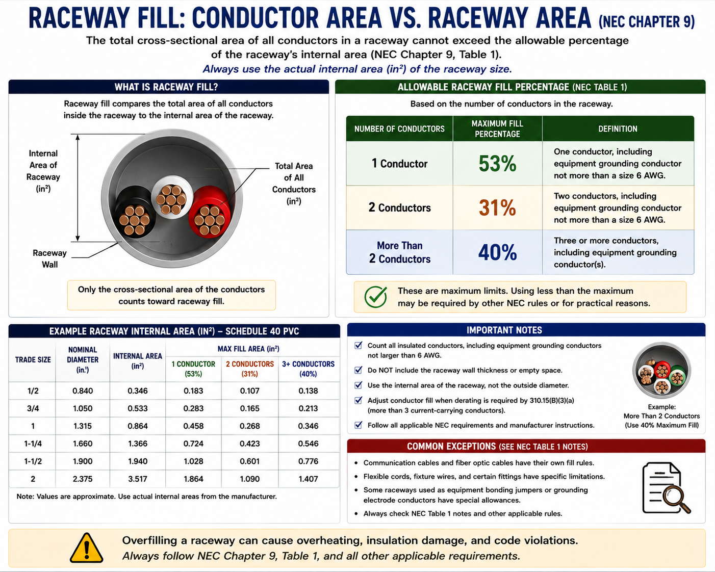
53%, 31%, and 40%
The basic raceway-fill limits are determined by the number of conductors or cables installed in the raceway.
1 Conductor or Cable
53% maximum raceway fill.
2 Conductors or Cables
31% maximum raceway fill.
More Than 2
40% maximum raceway fill.
One — Two — Three or More
A useful sequence to recognize is 53 — 31 — 40: one conductor uses 53 percent, two use 31 percent, and three or more use 40 percent.
Do not assume that fewer conductors always means a smaller percentage. The two-conductor condition has the lowest permitted percentage because two round conductors cannot use the circular raceway area as efficiently.
Raceway Fill Is an Installation Requirement
Fill limits are intended to provide practical space for conductor installation. Conductors forced into an undersized raceway can experience excessive pulling tension, insulation abrasion, deformation, and difficulty making bends or passing through fittings.
Raceway fill should therefore be considered during design rather than only after the conductors have already been installed.
Pulling Space
Available space reduces friction and allows conductors to move through the raceway during installation.
Insulation Protection
Proper fill helps reduce mechanical damage to insulation during pulling.
Bends and Fittings
Conductors need sufficient space to pass through bends and fittings without becoming jammed or damaged.
Future Work
A raceway installed near its maximum permitted fill can make future conductor additions difficult or impossible.
Know Which Table Provides Which Information
Table 1
Provides the allowable percentage of raceway cross-sectional area based on the number of conductors or cables.
Table 4
Provides dimensions and allowable percentage-fill areas for various types and sizes of conduit and tubing.
Table 5
Provides approximate dimensions and cross-sectional areas for insulated conductors and fixture wires.
Table 5A
Provides dimensions for compact insulated conductors where those conductor constructions are used.
Table 8
Provides conductor properties and areas for bare conductors.
Informative Annex C
Provides convenient conductor-count tables for many combinations of raceway type, conductor size, and insulation type when all conductors are the same size and type.
Conductor Insulation Changes Raceway Fill
Raceway fill uses the outside dimensions of the insulated conductor, not only the bare metal conductor size. Two conductors with the same AWG size can have different cross-sectional areas when their insulation types or constructions differ.
Always identify the conductor type stated in the problem before selecting its area from Chapter 9.
Example THHN Conductor Areas
For common THHN conductors, Chapter 9 Table 5 provides the approximate cross-sectional area of the conductor including its insulation. These values are frequently encountered in raceway-fill calculations.
14 AWG THHN
0.0097 in²
12 AWG THHN
0.0133 in²
10 AWG THHN
0.0211 in²
8 AWG THHN
0.0366 in²
6 AWG THHN
0.0507 in²
4 AWG THHN
0.0824 in²
Do Not Substitute Box-Fill Values
The cubic-inch allowances used in Lesson 50 for box fill are not conductor areas and cannot be used for raceway fill. For example, the 2.25 cubic-inch allowance for a 12 AWG conductor in a box is completely different from the approximately 0.0133 square-inch area of a 12 AWG THHN conductor used for raceway fill.
Box fill uses volume. Raceway fill uses cross-sectional area.
Standard Raceway-Fill Workflow
Count the Conductors and Cables
Determine whether the raceway contains one, two, or more than two conductors or cables.
Select the Fill Percentage
Use Chapter 9 Table 1 to select 53 percent, 31 percent, or 40 percent.
Determine Conductor Areas
Use Chapter 9 Table 5, Table 5A, Table 8, or actual dimensions as applicable.
Calculate Total Conductor Area
Multiply each conductor area by its quantity and add the results.
Select the Raceway Type
Identify whether the raceway is EMT, PVC, RMC, IMC, or another wiring method.
Use Table 4
Find a raceway whose allowable fill area is at least equal to the total conductor area.
Select the Smallest Compliant Raceway
If the question asks for minimum raceway size, select the first trade size whose allowable area is not less than the conductor area required.
Eight 12 AWG THHN Conductors
Assume eight 12 AWG THHN conductors will be installed in EMT. Because there are more than two conductors, Chapter 9 Table 1 permits a maximum fill of 40 percent.
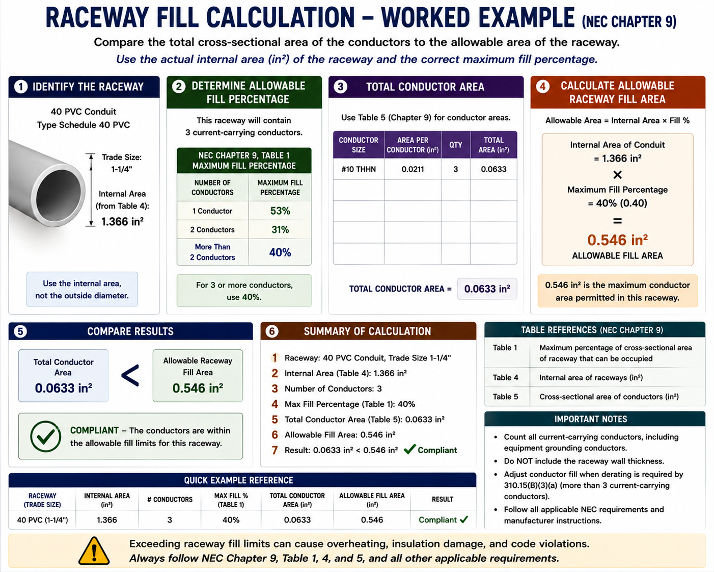
Step 1 — Determine the Area of One Conductor
Chapter 9 Table 5 gives an approximate area of 0.0133 square inches for one 12 AWG THHN conductor.
Step 2 — Calculate Total Conductor Area
Multiply the area of one conductor by the number of conductors.
8 × 0.0133 in² = 0.1064 in²
The raceway must therefore provide at least 0.1064 square inches of allowable conductor-fill area.
Step 3 — Select the Correct Fill Column
Because there are eight conductors, the installation falls into the more-than-two-conductor category.
Maximum permitted fill = 40%
Step 4 — Compare With the Raceway Table
Use the EMT portion of Chapter 9 Table 4 and look in the 40-percent fill column. Select the smallest EMT trade size whose allowable area is at least 0.1064 square inches.
For this example, 1/2-inch EMT provides sufficient 40-percent fill area for eight 12 AWG THHN conductors.
Add Each Conductor Group Separately
When a raceway contains several conductor sizes, calculate the area of each group and then add them together. Do not use an average conductor size.
12 AWG Group
Multiply the number of 12 AWG conductors by the Table 5 area for the specified insulation type.
10 AWG Group
Multiply the number of 10 AWG conductors by their applicable Table 5 area.
Other Conductors
Repeat for each remaining size and conductor type.
Add the Areas
The sum is the total conductor area that must fit within the allowable raceway-fill area.
Four 12 AWG and Three 10 AWG THHN Conductors
Assume the raceway contains four 12 AWG THHN conductors and three 10 AWG THHN conductors.
12 AWG THHN area:
4 × 0.0133 = 0.0532 in²
10 AWG THHN area:
3 × 0.0211 = 0.0633 in²
Total conductor area:
0.0532 + 0.0633 = 0.1165 in²
Because seven conductors are installed, use the 40-percent raceway-fill column and select a raceway providing at least 0.1165 square inches of allowable area.
Do Not Compare Total Conductor Area With Total Raceway Area
When using Chapter 9 Table 4, compare the conductor area with the allowable percentage-fill area for the number of conductors involved. Do not compare the conductor total with the raceway’s full 100-percent internal area unless you are first applying the correct Table 1 percentage yourself.
EGCs Count for Raceway Fill
Equipment grounding conductors and equipment bonding conductors installed in a raceway must be included when calculating raceway fill. This is different from the specialized grouping rule used for equipment grounding conductors in box-fill calculations.
For raceway fill, use the actual applicable cross-sectional area of each grounding or bonding conductor. If the conductor is insulated, use the applicable insulated-conductor area. If it is bare, use the actual dimensions or appropriate Chapter 9 information.
Grounding Conductors Are Treated Differently
In box-fill calculations, multiple equipment grounding conductors are combined according to the special allowances of 314.16(B)(5). Raceway fill does not use that method.
When grounding or bonding conductors occupy a raceway, their actual conductor area contributes to raceway fill. :contentReference[oaicite:1]{index=1}
Use the Correct Chapter 9 Area
Insulated conductors normally use Table 5 or Table 5A, while bare conductors can require information from Chapter 9 Table 8. Do not use the insulated THHN area for a bare equipment grounding conductor simply because both conductors have the same AWG size.
The insulation itself occupies raceway area, which is why an insulated conductor normally has a larger cross-sectional area than a bare conductor of the same conductor size.
The 24-Inch, 60-Percent Rule
Chapter 9 contains a special provision for qualifying conduit or tubing nipples not over 24 inches long between boxes, cabinets, and similar enclosures. These short nipples are permitted to contain conductors occupying up to 60 percent of the raceway’s total cross-sectional area.
This exception recognizes the relatively short pulling distance involved, but it applies only when the installation satisfies the conditions of the Chapter 9 note. :contentReference[oaicite:2]{index=2}
Do Not Apply 60% to Every Short Raceway
The 60-percent allowance is not a general fill rule for any raceway that happens to be short. It applies to qualifying nipples within the conditions specified by Chapter 9.
If the raceway is longer than the permitted nipple length or does not fit the stated application, return to the normal Table 1 fill percentages.
Cables Also Occupy Raceway Area
Chapter 9 Table 1 applies to conductors and cables installed in complete conduit or tubing systems. When a multiconductor cable is installed in a raceway, its outside dimensions must be considered when determining fill.
For cables or conductors not specifically listed in the Chapter 9 dimensional tables, use the actual dimensions as required by the Chapter 9 notes.
Use the Major Diameter Where Required
Some cables are not perfectly round. For an elliptical multiconductor cable, Chapter 9 rules require the area calculation to be based on a circle using the cable’s major diameter.
This prevents an irregularly shaped cable from being treated as though it occupied only its narrowest cross section.
Calculating Area From Diameter
If a cable’s outside diameter is known but a Chapter 9 table does not provide its area, the cross-sectional area of a round cable can be calculated from its diameter.
Area = π × (diameter ÷ 2)²
The resulting area can then be combined with the areas of the other conductors or cables installed in the raceway.
A Faster Method for Identical Conductors
Informative Annex C contains tables showing the maximum number of conductors permitted in many common conduit and tubing systems when all conductors are the same size and insulation type.
For straightforward exam questions involving identical conductors, Annex C can provide a faster answer than calculating individual conductor areas. For mixed conductor sizes or types, the Chapter 9 area method is generally required.
Use Annex C When the Problem Fits It
If every conductor is the same size and insulation type and the raceway type has an applicable Annex C table, checking Annex C can save substantial time.
If conductor sizes or types are mixed, return to Chapter 9 Tables 1, 4, and 5 and perform the area calculation.
EMT, PVC, RMC, and IMC Have Different Internal Areas
Raceways with the same nominal trade size do not necessarily have the same internal cross-sectional area. Wall thickness and construction vary among EMT, PVC, IMC, RMC, and other raceway systems.
Always use the Chapter 9 Table 4 section corresponding to the actual raceway type specified in the question.
Electrical Metallic Tubing
Use the Table 4 dimensions specifically provided for EMT.
Rigid PVC Conduit
Use the applicable PVC schedule and Table 4 dimensions rather than assuming the EMT area.
Intermediate Metal Conduit
Use the Table 4 information specifically provided for IMC.
Rigid Metal Conduit
Use the RMC dimensions rather than borrowing values from another metallic raceway.
Trade Size Is Not Internal Diameter
A raceway identified as 1 inch, 3/4 inch, or another trade size does not necessarily have that exact inside diameter. Trade size is a nominal designation.
Use the NEC raceway tables for actual internal area rather than calculating area from the nominal trade-size number.
Finding How Many Conductors Will Fit
Some exam questions provide a raceway size and ask for the maximum number of identical conductors permitted. The calculation can be performed by dividing the allowable raceway-fill area by the area of one conductor.
Maximum conductor count = Allowable raceway area ÷ Area of one conductor
The result must be rounded down to a whole conductor because exceeding the allowable fill is not permitted.
Round Down When Calculating Maximum Conductor Count
If the calculation produces 18.7 conductors, the maximum permitted quantity is 18, not 19. Raceway fill cannot exceed the permitted area merely because ordinary mathematical rounding would produce the larger number.
Raceway Fill and Conductor Adjustment Are Separate Calculations
A raceway can comply with the physical fill requirements and still create an ampacity problem. When multiple current-carrying conductors are installed together, conductor ampacity adjustment under 310.15(C)(1) may also apply.
Raceway fill asks whether the conductors physically fit within the permitted cross-sectional area. Ampacity adjustment asks whether the conductors can carry the required current under the thermal conditions created by the installation.
40% Fill Does Not Mean No Derating
A raceway containing many conductors can remain below the 40-percent fill limit while still requiring substantial ampacity adjustment because of the number of current-carrying conductors.
Always evaluate raceway fill and conductor ampacity as separate NEC requirements.
Why One Conductor Can Use 53%
When only one conductor or cable is installed in a raceway, Chapter 9 Table 1 permits it to occupy up to 53 percent of the raceway’s cross-sectional area.
The 53-percent rule is therefore the proper starting point for a raceway containing one large conductor or cable rather than automatically applying the familiar 40-percent value.
Two Conductors Use 31%
When exactly two conductors or cables are installed in the raceway, the maximum permitted fill is 31 percent.
This is an important exam detail because 31 percent is substantially lower than the 40-percent limit used when three or more conductors are installed.
Count Conductors Before Selecting the Percentage
Do not begin a raceway-fill calculation by automatically using 40 percent. First determine whether the raceway contains one conductor, two conductors, or more than two.
Solving Raceway-Fill Questions Efficiently
Identify the Raceway Type
Determine whether the question specifies EMT, PVC, RMC, IMC, or another conduit or tubing system.
Count Everything in the Raceway
Include circuit conductors, equipment grounding conductors, bonding conductors, and cables as applicable.
Select the Table 1 Percentage
Use 53 percent for one, 31 percent for two, or 40 percent for more than two unless a specific Chapter 9 provision changes the result.
Find Conductor Areas
Use the Chapter 9 table appropriate to the conductor construction.
Add the Areas
Determine the total occupied cross-sectional area.
Use Table 4
Locate the allowable fill area for the specified raceway type and percentage.
Select the Raceway
Choose the smallest raceway whose allowable fill area is equal to or greater than the required conductor area.
Check Related Requirements
Verify conductor ampacity adjustment, wiring-method requirements, bend limitations, and other rules independently from the physical fill calculation.
Think: Table 1 → Table 5 → Table 4
For a typical raceway-size problem, a useful navigation sequence is: use Table 1 to determine the permitted percentage, use Table 5 to determine conductor area, and use Table 4 to select the raceway.
If all conductors are identical, check Informative Annex C for a faster conductor-count method.
Code Locations to Know
300.17
General requirement limiting the number and size of conductors in a raceway and directing the user to the applicable Chapter 9 fill provisions.
Chapter 9 Table 1
Maximum percentage fill of conduit and tubing for conductors and cables.
Chapter 9 Table 4
Raceway dimensions and allowable fill areas for common conduit and tubing systems.
Chapter 9 Table 5
Dimensions and approximate areas of insulated conductors and fixture wires.
Chapter 9 Table 5A
Dimensions and areas for compact insulated conductors.
Chapter 9 Table 8
Conductor properties and areas used for bare conductors and other conductor information.
Chapter 9 Notes
Additional rules affecting raceway fill, equipment grounding conductors, short nipples, cables, and conductors not listed in the standard tables.
Informative Annex C
Maximum conductor-count tables for many combinations of identical conductors and raceway types.
310.15(C)(1)
Ampacity adjustment for multiple current-carrying conductors, which is evaluated separately from raceway fill.
Key Points to Remember
- Raceway fill is based on cross-sectional area, not cubic volume.
- Chapter 9 Table 1 permits 53 percent fill for one conductor or cable.
- Table 1 permits 31 percent fill for exactly two conductors or cables.
- Table 1 permits 40 percent fill for more than two conductors or cables.
- Do not automatically use 40 percent before counting the conductors.
- Chapter 9 Table 4 provides raceway dimensions and allowable fill areas.
- Chapter 9 Table 5 provides approximate areas for insulated conductors.
- Table 5A applies to compact insulated conductors where applicable.
- Table 8 can provide information for bare conductors.
- Conductor insulation type affects the cross-sectional area used for fill.
- A 12 AWG THHN conductor occupies approximately 0.0133 square inches.
- Mixed conductor sizes must be calculated individually and then added together.
- Equipment grounding and bonding conductors installed in the raceway count toward raceway fill.
- The special box-fill grouping rule for grounding conductors does not apply to raceway fill.
- Qualifying nipples not over 24 inches can be permitted up to 60 percent fill under the Chapter 9 provisions.
- The 60-percent nipple rule is not a general rule for every short raceway.
- Raceways of the same nominal trade size can have different internal areas depending on raceway type and construction.
- Trade size should not be treated as the actual inside diameter of the raceway.
- Multiconductor cables installed in raceway also occupy fill area.
- For conductors or cables not listed in the dimensional tables, actual dimensions may be required.
- When determining the maximum number of conductors, divide allowable raceway area by conductor area and round down.
- Informative Annex C can simplify calculations when all conductors are the same size and type.
- Raceway fill and ampacity adjustment are separate requirements.
- A raceway can comply with the 40-percent physical-fill limit and still require conductor ampacity adjustment under 310.15(C)(1).
Leave a Reply
You must be logged in to post a comment.