Back to: NASCLA Master Electrical Contractor Exam Preparation
Pull boxes and junction boxes provide access to conductors in raceway systems and create the space needed for pulling, changing direction, splicing, and maintaining larger conductors. When conductors 4 AWG and larger are involved, NEC 314.28 establishes minimum box dimensions based primarily on the raceway arrangement and trade sizes.
For the NASCLA Electrical Contractor Exam, you should be able to distinguish straight pulls, angle pulls, U pulls, and splice arrangements; calculate the minimum box dimensions for each; determine raceway-entry spacing; and recognize when several calculations must be compared to determine the controlling box dimension.
Large Conductors Need Pulling Space
Large conductors cannot make sharp turns inside small boxes without risking insulation damage or violating conductor bending requirements. Article 314 therefore establishes dimensional rules for pull boxes, junction boxes, and conduit bodies containing conductors 4 AWG and larger.
The calculation is based primarily on how the conductors travel through the box. A conductor passing directly from one wall to the opposite wall creates a straight pull. A conductor changing direction creates an angle pull. A conductor entering and leaving the same wall creates a U pull.
314.28 Applies to 4 AWG and Larger Conductors
The dimensional pull-box rules of 314.28 are especially important when insulated conductors 4 AWG and larger are installed in raceways or cable systems covered by the section.
These requirements are different from the cubic-inch box-fill calculations developed in Lesson 50. Large-conductor boxes are sized primarily to provide adequate pulling and bending space.
Four Arrangements to Recognize
Straight Pull
Conductors enter through one wall of the box and leave through the opposite wall without changing direction.
Angle Pull
Conductors enter through one wall and leave through an adjacent wall, creating a change in direction.
U Pull
Conductors enter and leave through the same wall, causing them to reverse direction inside the enclosure.
Splices
Where conductors are spliced within the box, the sizing method follows the applicable 314.28(A)(2) dimensional requirements rather than the straight-pull rule.
Straight = 8 • Angle/U/Splice = 6 + Others
A useful starting point is:
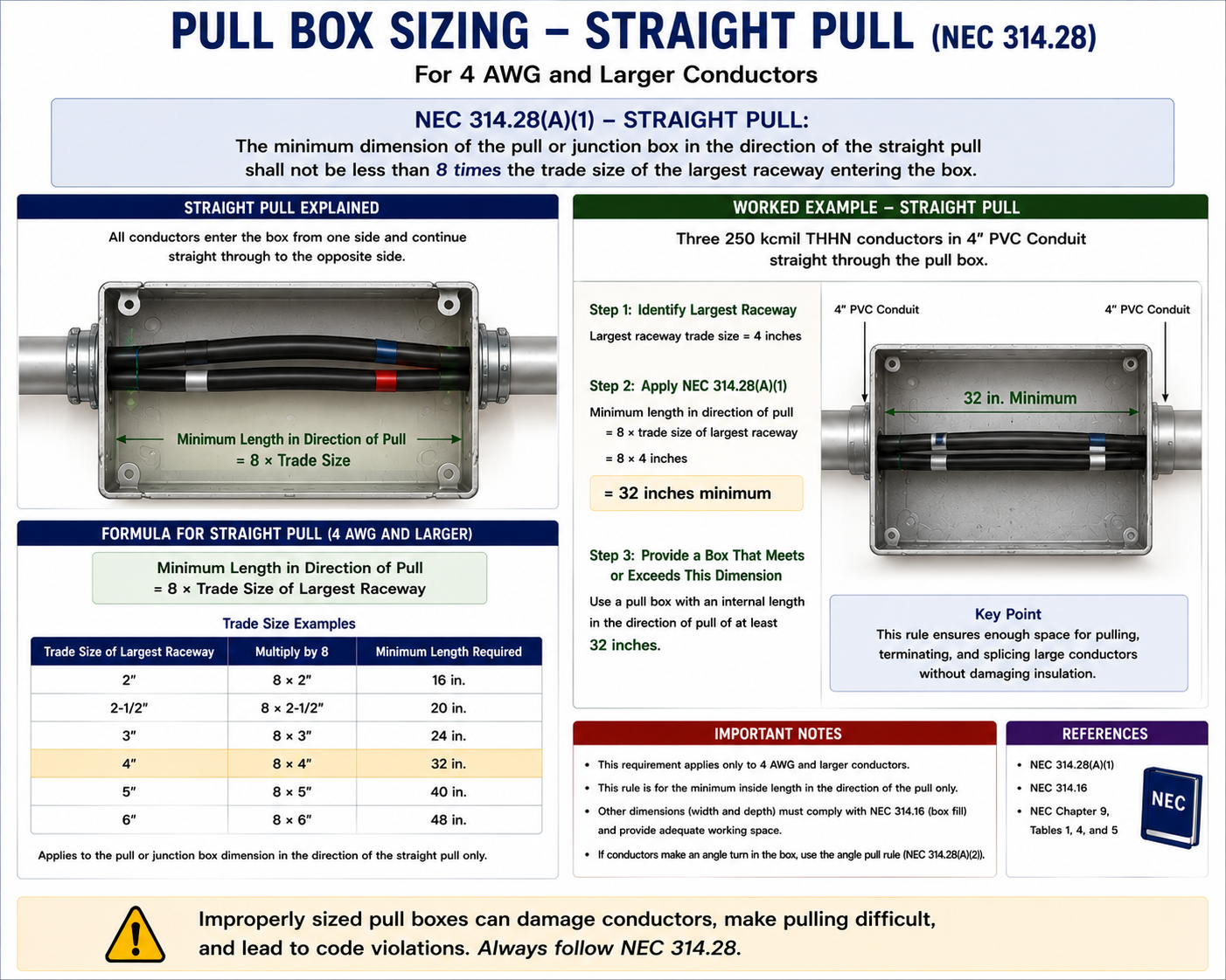
Straight pull: 8 × largest raceway
Angle pull, U pull, or splice: 6 × largest raceway + remaining raceways in the same row
The actual calculation must still follow the exact raceway arrangement shown in the problem.
314.28(A)(1)
A straight pull occurs when conductors enter one wall of the enclosure and leave through the opposite wall. The minimum distance from the raceway entry to the opposite wall must be at least eight times the trade size of the largest raceway containing the conductors involved in the straight pull.
The calculation is based on raceway trade size, not conductor diameter and not the raceway’s measured outside diameter.
Minimum Dimension = 8 × Largest Raceway Trade Size
If the largest raceway involved in a straight pull is 3 inches:
8 × 3 in. = 24 in.
The required box dimension in the direction of the pull must therefore be at least 24 inches.
Two 2-Inch Raceways on Opposite Walls
Assume conductors enter a pull box through a 2-inch raceway on the left wall and leave through another 2-inch raceway directly opposite on the right wall.
Identify the Pull
The raceways are on opposite walls, so this is a straight pull.
Identify the Largest Raceway
The largest raceway involved is 2 inches.
Apply the Straight-Pull Multiplier
8 × 2 in. = 16 in.
Minimum Box Dimension
The box must provide at least 16 inches in the direction of the pull.
Do Not Multiply Every Raceway by Eight
For a straight pull, the minimum dimension is based on eight times the trade size of the largest raceway involved in that straight pull. The smaller raceways are not added to the straight-pull calculation.
314.28(A)(2)
An angle pull occurs when conductors enter through one wall of the box and leave through an adjacent wall. Because the conductors must bend inside the enclosure, the calculation requires more than simply multiplying a raceway size by a fixed number.
For each applicable raceway-entry row, the distance from the raceway entry to the opposite wall must be at least six times the trade size of the largest raceway in that row, plus the sum of the trade sizes of the remaining raceways in the same row on that wall.
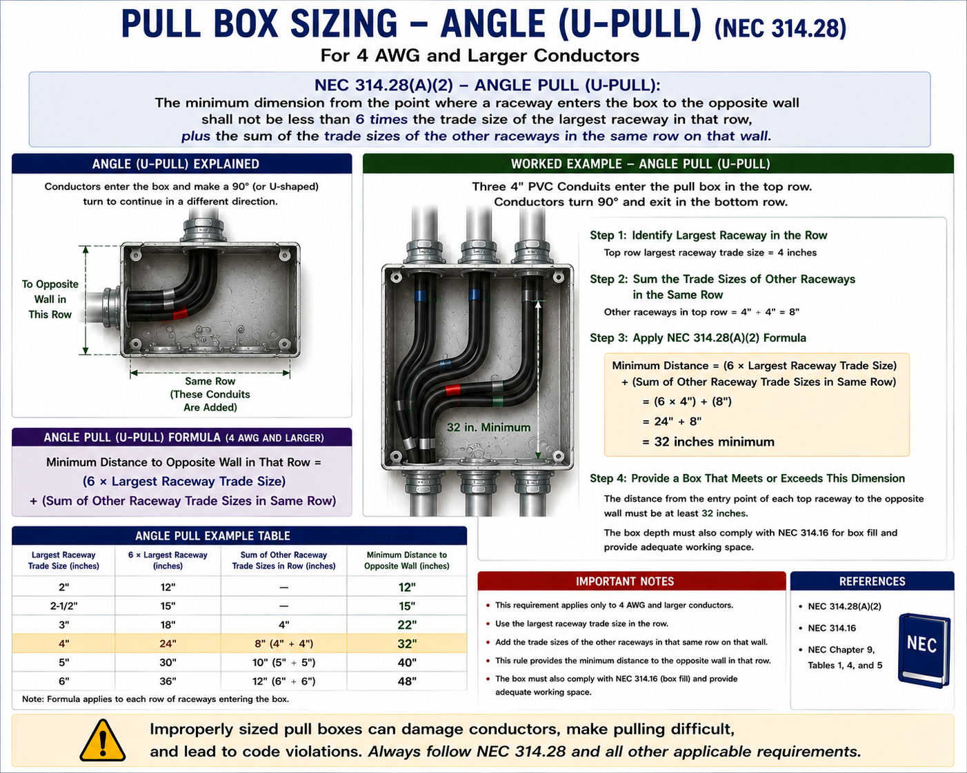
6 × Largest Raceway + Remaining Raceway Sizes
For a row containing one 3-inch raceway and one 2-inch raceway:
(6 × 3 in.) + 2 in. = 20 in.
The required distance from that raceway-entry wall to the opposite wall is therefore at least 20 inches.
Multiple Entries Occupy Pulling Space
When several raceways enter the same wall and row, they compete for conductor bending and pulling space inside the box. Article 314.28 therefore adds the trade sizes of the other raceways in that row to the six-times-largest-raceway calculation.
The largest raceway receives the multiplier. The other applicable raceways in the same row are added once.
Do Not Multiply Every Raceway by Six
For an angle-pull row, multiply only the largest raceway in the row by six. Then add the trade sizes of the remaining raceways in that same row.
For example, a row with 3-inch, 2-inch, and 1-inch raceways is calculated as:
(6 × 3) + 2 + 1 = 21 inches
Calculate Each Raceway Row Separately
If more than one row of raceways enters the same wall, each row is calculated separately. The row requiring the greatest distance determines the minimum box dimension for that wall.
Do not combine raceways from separate rows into one calculation unless the Code arrangement requires them to be considered together.
Compare the Results
Row 1
3-inch + 2-inch raceways:
(6 × 3) + 2 = 20 in.
Row 2
2-inch + 2-inch + 1-inch raceways:
(6 × 2) + 2 + 1 = 15 in.
The first row requires the greater dimension, so the box must provide at least 20 inches in that direction.
Conductors Enter and Leave the Same Wall
A U pull occurs when conductors enter the enclosure and return through another raceway located on the same wall. The conductors must reverse direction inside the box.
U pulls use the 314.28(A)(2) sizing approach: six times the largest raceway in the applicable row plus the sum of the trade sizes of the remaining raceways in that row.
Same Wall Does Not Mean Straight Pull
If conductors enter and leave through raceways on the same wall, the pull is not straight even if the raceways are aligned horizontally. The conductors must reverse direction inside the box, so the U-pull rules apply.
Boxes Containing Splices
When conductors 4 AWG and larger are spliced within a junction box, the box must provide sufficient space for the conductors to enter, bend, splice, and leave without excessive stress.
For sizing purposes under 314.28(A)(2), boxes containing applicable splices use the same basic dimensional approach as angle and U pulls: six times the largest raceway in the row plus the sum of the remaining raceways in that row.
Pull Box vs. Junction Box
A pull box may simply provide access for conductor pulling without containing splices. A junction box may contain splices or taps. The name of the enclosure alone does not determine the sizing method.
Analyze what the conductors actually do inside the box.
Raceways Containing the Same Conductors
Angle and U pulls also require adequate spacing between raceway entries containing the same conductors. The distance between those raceway entries must provide sufficient room for the conductor bending path.
For the applicable arrangement, the required separation is based on six times the trade size of the largest raceway involved in that conductor path.
3-Inch Raceway to 3-Inch Raceway
If an angle-pull conductor path runs between two 3-inch raceways, the required raceway-entry separation is based on:
6 × 3 in. = 18 in.
The box can have adequate overall dimensions and still be noncompliant if the raceway entries are positioned too close together. :contentReference[oaicite:1]{index=1}
A Box Can Contain More Than One Type of Pull
One enclosure can contain straight pulls, angle pulls, U pulls, and splices at the same time. When that happens, perform every applicable calculation for each box dimension and use the largest result.
The fact that one set of raceways creates a straight pull does not eliminate an angle-pull calculation created by another set of conductors.
Straight Pull and Angle Pull on the Same Wall
Assume a box wall contains a 4-inch raceway involved in a straight pull and a 2-inch raceway involved in an angle pull.
Straight-Pull Calculation
8 × 4 in. = 32 in.
Angle-Pull Calculation
If the applicable row contains the 2-inch raceway together with the 4-inch raceway, the angle-pull calculation must also be completed according to the raceway arrangement.
Compare the Results
The larger required dimension controls.
Always Use the Largest Required Dimension
If several NEC calculations apply to the same box dimension, do not average them and do not choose the calculation that appears to be the primary purpose of the box.
Calculate all applicable conditions and use the largest minimum dimension produced.
Calculate Each Direction Independently
A pull box problem can require one calculation for its horizontal dimension and another for its vertical dimension. Raceway arrangements on the left and right walls affect one direction, while entries on the top and bottom walls can affect the other.
The final enclosure might therefore require dimensions such as 24 inches by 18 inches rather than a square box.
Work One Wall at a Time
Sketch the Box
Draw the four walls and place each raceway in approximately the location described by the question.
Trace Each Conductor Path
Determine whether each set of conductors makes a straight pull, angle pull, U pull, or splice.
Calculate Each Wall
Apply the appropriate 8-times or 6-times-plus-others rule to each applicable row.
Check Raceway Separation
For angle and U pulls, verify the required spacing between raceway entries containing the same conductors.
Compare Competing Calculations
If several calculations affect the same horizontal or vertical dimension, retain the largest result.
State the Minimum Box Size
Combine the controlling horizontal and vertical dimensions into the minimum enclosure dimensions.
Draw the Raceway Layout
Pull-box problems are much easier when converted from words into a simple sketch. Label each raceway with its trade size and use arrows to show the conductor path.
A 20-second sketch can prevent mixing raceways from different rows or applying the straight-pull rule to an angle pull.
Raceway Size, Not Conductor Ampacity
The 314.28 dimensional formulas use the trade sizes of the raceways associated with the conductors. The ampacity or circular-mil area of the conductors is not inserted directly into the eight-times or six-times calculation.
Conductor size remains important because it determines whether the 314.28 large-conductor provisions apply and because separate bending-space requirements may also affect the installation.
Do Not Multiply Conductor Size
A problem involving 4/0 conductors in a 3-inch raceway does not mean that 4/0 is multiplied by eight or six. Use the 3-inch raceway trade size in the 314.28 dimensional calculation.
Box Size Alone Is Not Enough
An enclosure can meet the minimum overall width and height yet still fail the NEC requirements because its raceway entries are positioned incorrectly. Raceway spacing must preserve the conductor bending path required by the Code.
This is particularly important in angle and U pulls, where two raceways containing the same conductors can be located too close together even inside a large enclosure.
Support in Very Large Enclosures
Article 314.28 also contains requirements affecting conductors installed in unusually large pull or junction boxes. Where a box dimension exceeds the threshold specified by the Code, conductors may require approved racking or support.
This prevents large conductors from placing excessive mechanical stress on terminations, splices, or other conductors within the enclosure. :contentReference[oaicite:2]{index=2}
Pull and Junction Boxes Require Suitable Covers
The box must be closed by a cover suitable for the enclosure and the conditions of use. Cover requirements are separate from the dimensional calculation and must still be satisfied after the correct box size has been determined.
Outdoor, wet, corrosive, or other special-location installations require enclosure and cover systems suitable for those environmental conditions.
Pull Points Must Remain Accessible
Pull boxes and junction boxes provide access to conductors for installation, inspection, maintenance, splicing, or replacement. They cannot fulfill that purpose if they are permanently buried behind inaccessible building finishes.
The completed installation must preserve the accessibility required by Article 314.
A Pull Box Can Reset a Raceway Bend Run
A pull box is often installed where a long raceway route or multiple bends would make conductor pulling impractical. Because the pull box creates an accessible pulling point, a new raceway section begins beyond the box for purposes of the bend limitations of the applicable raceway article.
The box itself must still be sized correctly for the conductors and raceways connected to it.
Example — 4-Inch Raceway
A raceway containing large conductors enters the left side of a pull box and exits directly opposite through another 4-inch raceway.
8 × 4 in. = 32 in.
The minimum horizontal dimension is 32 inches.
Example — 3-Inch, 2-Inch, and 2-Inch Raceway Row
Assume three raceways in the same row on one wall are involved in angle-pull conditions. Their trade sizes are 3 inches, 2 inches, and 2 inches.
(6 × 3 in.) + 2 in. + 2 in. = 22 in.
The required distance from that raceway-entry wall to the opposite wall is at least 22 inches.
Example — Two 2-Inch Raceways
Two 2-inch raceways are located in the same row on the same wall, and conductors leave one raceway, turn inside the box, and return through the other.
(6 × 2 in.) + 2 in. = 14 in.
The minimum distance from that raceway-entry wall to the opposite wall is therefore 14 inches.
Ask Three Questions
Before accepting a pull-box answer, ask:
Did I identify the correct pull type?
Did I use raceway trade size rather than conductor size?
Did I compare every applicable calculation and keep the largest result?
Code Locations to Know
314.28
General sizing and installation requirements for pull boxes, junction boxes, and conduit bodies involving larger conductors.
314.28(A)(1)
Straight-pull sizing requirements using eight times the trade size of the largest applicable raceway.
314.28(A)(2)
Angle pulls, U pulls, and splice arrangements using six times the largest raceway plus the remaining raceways in the same row.
314.28(B)
Requirements affecting conductor support in large pull or junction boxes.
314.28(C)
Cover requirements for pull and junction boxes.
314.28(D)
Requirements affecting permanent barriers within boxes.
314.28(E)
Requirements affecting power distribution blocks installed in pull or junction boxes.
314.29
Accessibility requirements for boxes, conduit bodies, and handhole enclosures.
Solve Pull-Box Questions Systematically
Check Conductor Size
Determine whether the conductors are large enough for 314.28 to apply.
Sketch the Enclosure
Mark all raceways and their trade sizes on the appropriate walls.
Trace the Conductors
Classify each path as straight, angle, U pull, or splice.
Apply the Correct Formula
Use eight times the largest raceway for straight pulls or six times the largest plus remaining raceways for applicable angle, U, and splice calculations.
Calculate Every Row
Where several rows exist, calculate them independently.
Check Raceway Separation
Verify spacing between entries containing the same conductors where required.
Select the Largest Result
Use the controlling horizontal and vertical dimensions to determine the minimum box size.
Key Points to Remember
- NEC 314.28 contains the primary dimensional rules for pull boxes and junction boxes involving conductors 4 AWG and larger.
- Pull-box sizing is different from the cubic-inch box-fill calculations of 314.16.
- A straight pull enters one wall and exits through the opposite wall.
- A straight-pull dimension is at least eight times the trade size of the largest applicable raceway.
- An angle pull enters one wall and exits through an adjacent wall.
- A U pull enters and leaves through the same wall.
- Angle pulls, U pulls, and applicable splice arrangements use six times the largest raceway plus the remaining raceways in the same row.
- Multiply only the largest raceway in an angle-pull row by six.
- Add the trade sizes of the remaining raceways in that same row once.
- Multiple raceway rows must be calculated separately.
- The row producing the largest required dimension controls.
- Raceways containing the same conductors in angle and U pulls must also have adequate separation.
- An enclosure can meet its overall dimensions and still fail because raceway entries are too close together.
- A single box can contain straight pulls, angle pulls, U pulls, and splices simultaneously.
- When several calculations apply to the same dimension, use the largest result.
- Horizontal and vertical box dimensions may require separate calculations.
- The formulas use raceway trade size, not conductor AWG or circular-mil size.
- A pull box may provide a new accessible pulling point in a long or heavily bent raceway route.
- Large boxes can also require conductor support, suitable covers, and continued accessibility.
- A quick sketch of the raceway arrangement is one of the most effective ways to prevent exam errors.
Leave a Reply
You must be logged in to post a comment.