Back to: NASCLA Master Electrical Contractor Exam Preparation
Electrical boxes must provide enough free space for the conductors, equipment grounding conductors, devices, internal clamps, and other components installed inside them. NEC 314.16 establishes a systematic method for determining the minimum box volume required for these components.
For the NASCLA Electrical Contractor Exam, box-fill problems are best solved by counting each component according to the specific rules of 314.16(B), converting those counts into cubic-inch volume using Table 314.16(B), and comparing the required volume with the available volume of the selected box.
Box Fill Is a Volume Calculation
Box fill is not based simply on whether the conductors can physically be pushed into the enclosure. Each conductor and certain other components require a specific amount of free space based on conductor size.
The calculation has two sides: the minimum volume required by everything installed inside the box and the actual volume provided by the box and any qualifying extension components. The available volume must be at least equal to the required volume.
Required Volume Must Not Exceed Available Volume
Required box volume ≤ Available box volume
The required volume is calculated using 314.16(B). The available volume is determined using the box volume provisions of 314.16(A), including applicable table values, manufacturer markings, and qualifying extension components.
Know the Volume Allowance Per Conductor
Table 314.16(B) assigns a minimum volume allowance to each conductor based on its AWG size. Larger conductors require more space.
18 AWG
1.50 cubic inches per conductor allowance.
16 AWG
1.75 cubic inches per conductor allowance.
14 AWG
2.00 cubic inches per conductor allowance.
12 AWG
2.25 cubic inches per conductor allowance.
10 AWG
2.50 cubic inches per conductor allowance.
8 AWG
3.00 cubic inches per conductor allowance.
6 AWG
5.00 cubic inches per conductor allowance.
Start With the Conductor Size
Many exam questions provide the box dimensions, conductor count, and conductor size. Once you know the size of each conductor, Table 314.16(B) converts the conductor count into required cubic inches.
Do not assume every conductor requires the same volume if the box contains multiple conductor sizes.
314.16(B)(1)
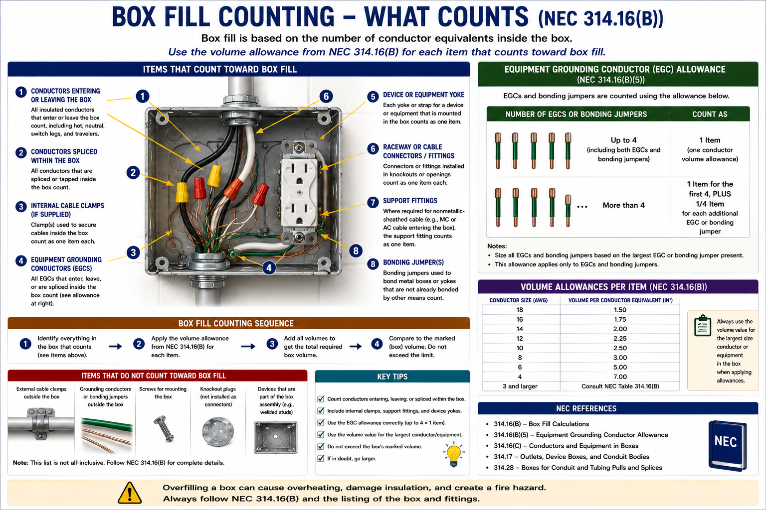
Each insulated conductor that originates outside the box and terminates or is spliced inside the box is counted once. Each conductor that passes completely through the box without splice or termination is also counted once.
A conductor that begins and ends entirely within the box, such as a typical pigtail used to connect a splice to a device, does not receive an additional conductor-fill allowance under this rule.
Conductor Terminates
A conductor entering the box and terminating on a device or other connection counts once.
Conductor Is Spliced
A conductor entering the box and being spliced to another conductor counts once.
Conductor Passes Through
An unspliced conductor entering and leaving the box counts once.
Internal Pigtail
A conductor that originates and terminates entirely within the box does not receive an additional conductor-fill allowance.
A Splice Does Not Make One Conductor Count Twice
If a conductor enters the box and is spliced inside the box, that entering conductor receives one conductor allowance. The fact that it terminates in a splice does not cause it to be counted a second time.
Count conductors according to how they enter, leave, terminate, or pass through the box rather than according to the number of wire connectors used.
Loops of Unbroken Conductor
An unbroken loop or coil of conductor that is at least twice the minimum free-conductor length required by 300.14 must be counted twice for box-fill purposes.
This prevents a large coil of spare conductor from occupying substantial box volume without being reflected in the calculation.
314.16(B)(2)
Where one or more internal cable clamps are present inside the box, the entire group of internal clamps receives a single volume allowance based on the largest conductor present in the box.
A cable connector whose clamping mechanism is outside the box does not receive this internal clamp allowance.
One Internal Clamp
Count one conductor-volume allowance based on the largest conductor in the box.
Multiple Internal Clamps
The group still receives one conductor-volume allowance rather than one allowance for every clamp.
External Clamp
A connector with its clamping mechanism outside the box does not receive an internal clamp fill allowance.
Internal Clamp With 12 AWG Conductors
If the largest conductor in a box is 12 AWG and the box contains one or more internal cable clamps, the clamp allowance is one 12 AWG conductor volume.
1 × 2.25 in³ = 2.25 in³
314.16(B)(3)
Where luminaire studs or hickeys are present in a box, these support fittings also require volume allowances. Each type of support fitting receives a single conductor-volume allowance based on the largest conductor present in the box.
These fittings are less common in basic box-fill examples but are important because they occupy physical space inside the enclosure.
314.16(B)(4)
Each yoke or strap containing one or more devices or pieces of equipment receives a double volume allowance. The allowance is based on the largest conductor connected to a device or equipment supported by that yoke.
A typical single receptacle yoke therefore counts as two conductor volumes. A switch mounted on a single yoke also counts as two conductor volumes.
Single Receptacle Yoke
Counts as two conductor-volume allowances based on the largest conductor connected to the device.
Single Switch Yoke
Also counts as two conductor-volume allowances based on the largest conductor connected to the switch.
Multiple Devices on One Yoke
The yoke rule applies to the strap or yoke rather than simply counting the number of device functions.
Wider Equipment
Devices or equipment requiring more than one gang receive additional double allowances as specified by 314.16(B)(4).
Receptacle With 12 AWG Conductors
A single-gang receptacle mounted on one yoke and connected to 12 AWG conductors requires two 12 AWG conductor allowances.
2 × 2.25 in³ = 4.50 in³
314.16(B)(5)
The equipment grounding conductor calculation is different from the rules for ordinary insulated conductors. Where up to four equipment grounding conductors or equipment bonding jumpers enter the box, the group receives one full volume allowance based on the largest equipment grounding conductor or equipment bonding jumper entering the box.
For each additional equipment grounding conductor or equipment bonding jumper entering the box beyond the first four, add one-quarter of a conductor-volume allowance based on the largest equipment grounding conductor or bonding jumper.
1–4 EGCs
One full volume allowance based on the largest equipment grounding conductor or equipment bonding jumper entering the box.
5th EGC
Add one-quarter of the applicable conductor-volume allowance.
6th EGC
Add another one-quarter allowance.
Additional EGCs
Continue adding one-quarter allowance for each additional equipment grounding conductor or bonding jumper entering the box.
Do Not Use the Older “All Grounds Count as One” Rule
Older training material may state that all equipment grounding conductors together count as one conductor volume regardless of quantity. That is no longer the complete current rule.
Under the current calculation method, up to four equipment grounding conductors or bonding jumpers receive one full allowance, and each additional conductor or jumper adds one-quarter of an allowance.
Six 12 AWG Equipment Grounding Conductors
Assume six 12 AWG equipment grounding conductors enter a box. The first four receive one full 12 AWG allowance. The fifth and sixth each add one-quarter of an allowance.
First Four EGCs
One full allowance = 1.00 conductor equivalent.
Fifth EGC
Add 0.25 conductor equivalent.
Sixth EGC
Add another 0.25 conductor equivalent.
Total
1.00 + 0.25 + 0.25 = 1.50 conductor equivalents.
For 12 AWG conductors:
1.50 × 2.25 in³ = 3.375 in³
A Reliable Box-Fill Workflow
Count Insulated Conductors
Count conductors entering and terminating, being spliced, or passing through according to 314.16(B)(1).
Count Internal Clamps
If internal clamps are present, add one allowance based on the largest conductor in the box.
Count Support Fittings
Add the required allowance for luminaire studs or hickeys where present.
Count Device Yokes
Add two conductor allowances for each applicable device yoke based on the largest conductor connected to that yoke.
Count EGCs
Apply the one-full-plus-quarter-allowances method required by 314.16(B)(5).
Convert Counts to Volume
Multiply each conductor equivalent by the appropriate cubic-inch allowance from Table 314.16(B).
Add the Volumes
Add all required volume allowances to determine the minimum box volume.
Compare With Available Volume
Verify that the selected box provides at least the calculated minimum volume.
Box Fill With a Receptacle
Consider a box containing two 12/2 NM cables. One cable brings power into the box and the second continues the circuit. The box contains one receptacle mounted on a single yoke, internal cable clamps, and two 12 AWG equipment grounding conductors entering with the cables.
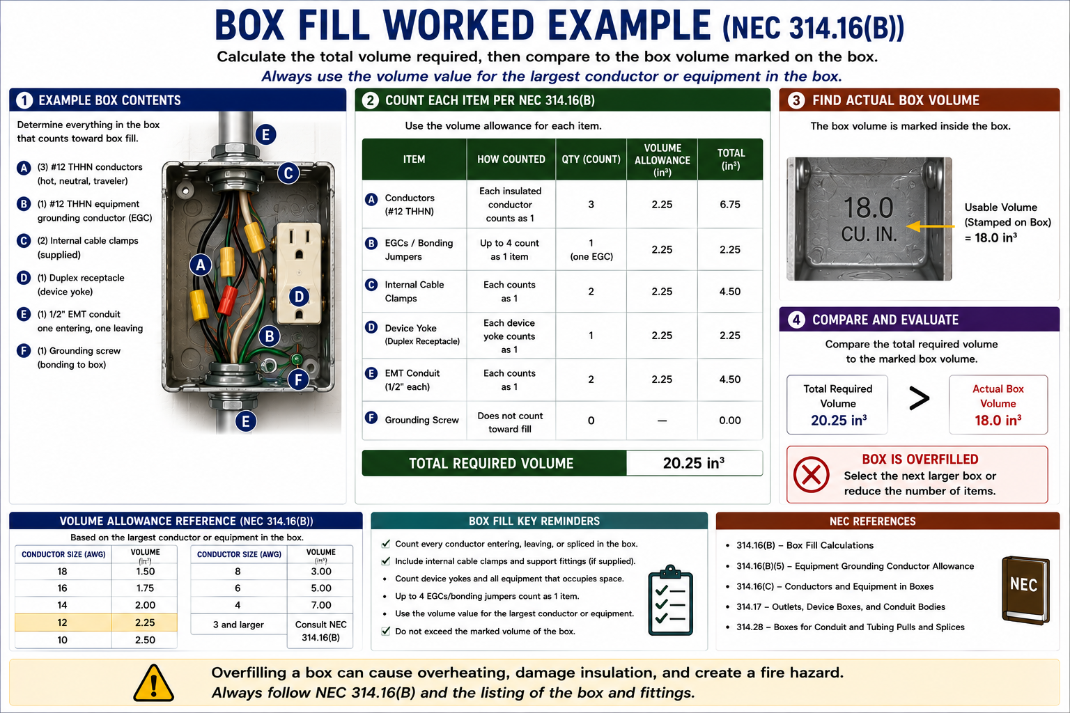
Step 1 — Count the Insulated Conductors
Each 12/2 cable contains two insulated current-carrying conductors. With two cables entering the box, there are four insulated 12 AWG conductors that must be counted.
4 conductor equivalents
Step 2 — Count the Internal Clamp
The box contains internal cable clamps. One or more internal clamps together receive one conductor-volume allowance based on the largest conductor in the box.
1 conductor equivalent
Step 3 — Count the Receptacle Yoke
The receptacle is mounted on one yoke. A single yoke receives two conductor-volume allowances based on the largest conductor connected to the device.
2 conductor equivalents
Step 4 — Count the Equipment Grounding Conductors
Two 12 AWG equipment grounding conductors enter the box. Because there are no more than four, the group receives one full conductor-volume allowance.
1 conductor equivalent
Step 5 — Add the Conductor Equivalents
Insulated conductors: 4
Internal clamps: 1
Receptacle yoke: 2
Equipment grounding conductors: 1
Total = 8 conductor equivalents
Step 6 — Convert to Cubic Inches
All conductor equivalents in this example are based on 12 AWG conductors. Table 314.16(B) assigns 2.25 cubic inches to each 12 AWG conductor allowance.
8 × 2.25 in³ = 18.00 in³
The selected box must therefore provide at least 18.00 cubic inches of usable volume.
Calculate Each Size Separately
When a box contains more than one conductor size, do not add all conductor equivalents together and multiply by one volume value. Calculate the volume associated with each conductor size separately and then add the results.
Example
Five 14 AWG equivalents require:
5 × 2.00 = 10.00 in³
Example
Six 12 AWG equivalents require:
6 × 2.25 = 13.50 in³
Total required volume:
10.00 + 13.50 = 23.50 in³
Do Not Average Conductor Sizes
If a box contains both 14 AWG and 12 AWG conductors, each group must use the cubic-inch allowance appropriate to that conductor size. Do not use an average conductor size or automatically calculate everything using the most common conductor in the box.
Determine the Capacity of the Box
After determining the required volume, compare it with the actual capacity of the box. Standard metal box volumes can be obtained from Table 314.16(A), while many other boxes are marked by the manufacturer with their cubic-inch capacity.
Qualifying extension rings, plaster rings, domed covers, and similar components can add volume when they are marked with their volume or otherwise meet the requirements of 314.16(A).
Table Value
Use Table 314.16(A) for standard boxes covered by the table.
Marked Volume
Use the manufacturer’s marked capacity where required or permitted.
Extension Volume
Add qualifying marked extension-ring or similar component volume where permitted.
Final Comparison
Available box volume must be equal to or greater than the calculated required volume.
Required 18.00 in³ — Box Rated 18.0 in³
If the calculated minimum required volume is exactly 18.00 cubic inches and the selected box has a listed or marked capacity of 18.0 cubic inches, the volume requirement is satisfied.
A larger box may make installation easier, but the Code calculation establishes the minimum acceptable volume.
Do Internal Pigtails Count?
A conductor that originates and terminates entirely within the box does not receive a conductor-fill allowance under 314.16(B)(1). A typical pigtail from a splice to a switch or receptacle therefore does not count as another insulated conductor merely because it occupies space.
The device yoke itself still receives the required device-fill allowance, and equipment grounding conductors and bonding jumpers must still be evaluated under their specific rule.
Do Not Count Wire Connectors as Conductors
Small fittings such as ordinary wire connectors, locknuts, and bushings do not receive separate box-fill allowances under 314.16(B).
Count only the items for which the Code specifically requires a volume allowance.
Distinguish Conductors Entering the Box From Internal Jumpers
The equipment-grounding fill rule focuses on equipment grounding conductors and bonding jumpers entering the box and applies the specified group allowance. A short grounding connection that exists entirely inside the box should not automatically be counted as though another cable entered the enclosure.
Read the wording of 314.16(B)(5) carefully when a problem includes several equipment grounding conductors, bonding jumpers, or grounding connections.
When 314.28 Also Applies
Boxes and conduit bodies containing conductors 4 AWG and larger are subject to the additional sizing provisions of 314.28. Those requirements address pulling space and raceway arrangement and are not replaced by a simple cubic-inch box-fill calculation.
Lesson 52 will examine straight pulls, angle pulls, U pulls, and junction-box sizing for larger conductors.
Build a Fill Inventory Before Doing Math
The fastest and most reliable approach is to inventory the contents of the box before multiplying anything. This prevents the common mistake of forgetting a device yoke, internal clamp, or equipment grounding allowance.
List Each Conductor Size
Separate 14 AWG, 12 AWG, 10 AWG, and other conductor sizes into individual groups.
Count Insulated Conductors
Apply 314.16(B)(1) to conductors entering, terminating, splicing, passing through, or forming qualifying loops.
Add Clamp and Support Fitting Fill
Determine whether internal clamps, studs, or hickeys require additional allowances.
Add Device Fill
Add the required double allowance for each applicable yoke or strap.
Add EGC Fill
Count the first four equipment grounding conductors or bonding jumpers as one allowance and add one-quarter allowance for each additional one.
Convert to Cubic Inches
Use Table 314.16(B) for the appropriate conductor size.
Compare With Box Capacity
Verify that the selected box provides at least the required cubic-inch volume.
314.16(B) Is Organized by What Occupies the Box
The box-fill rules become much easier to navigate when you associate each paragraph with an item: (B)(1) conductors, (B)(2) clamps, (B)(3) support fittings, (B)(4) devices and equipment, and (B)(5) equipment grounding conductors.
On an open-book examination, this structure allows you to verify the exact counting rule instead of relying on memory.
Code Locations to Know
314.16(A)
Determines available box volume, including standard boxes, marked boxes, and qualifying extension components.
Table 314.16(A)
Provides dimensions and volume capacities for common standard metal boxes.
314.16(B)
Establishes the overall box-fill calculation method.
314.16(B)(1)
Conductor fill.
314.16(B)(2)
Internal cable clamp fill.
314.16(B)(3)
Support fitting fill.
314.16(B)(4)
Device and equipment yoke fill.
314.16(B)(5)
Equipment grounding conductor and equipment bonding jumper fill.
Table 314.16(B)
Provides the required cubic-inch volume allowance for each conductor size.
300.14
Free-conductor length requirements, which also affect the treatment of long unbroken loops in box-fill calculations.
314.28
Additional sizing provisions for boxes and conduit bodies containing conductors 4 AWG and larger.
Key Points to Remember
- Box fill is governed primarily by NEC 314.16.
- The available box volume must be equal to or greater than the calculated required volume.
- Table 314.16(B) assigns a cubic-inch allowance based on conductor size.
- 14 AWG requires 2.00 cubic inches per allowance.
- 12 AWG requires 2.25 cubic inches per allowance.
- 10 AWG requires 2.50 cubic inches per allowance.
- 8 AWG requires 3.00 cubic inches per allowance.
- 6 AWG requires 5.00 cubic inches per allowance.
- Each insulated conductor entering and terminating or being spliced in the box generally counts once.
- An unspliced conductor passing through the box counts once.
- A conductor that originates and terminates entirely inside the box generally does not receive a conductor-fill allowance.
- A qualifying long loop of unbroken conductor can count twice.
- One or more internal cable clamps receive one conductor allowance based on the largest conductor present.
- External cable clamps do not receive the internal clamp allowance.
- Each device yoke generally receives two conductor-volume allowances based on the largest conductor connected to that device.
- Up to four equipment grounding conductors or equipment bonding jumpers entering a box receive one full volume allowance based on the largest one.
- Each additional equipment grounding conductor or bonding jumper beyond four adds one-quarter of the applicable allowance.
- Do not use the obsolete shortcut that every quantity of equipment grounding conductors always counts as only one full conductor volume.
- Mixed conductor sizes must be calculated separately using their individual Table 314.16(B) volume values.
- Wire connectors, locknuts, bushings, and similar small fittings do not normally receive individual box-fill allowances.
- Boxes containing conductors 4 AWG and larger must also be evaluated under 314.28.
- The most reliable exam method is to inventory every component before performing the arithmetic.
Leave a Reply
You must be logged in to post a comment.