Back to: NASCLA Master Electrical Contractor Exam Preparation
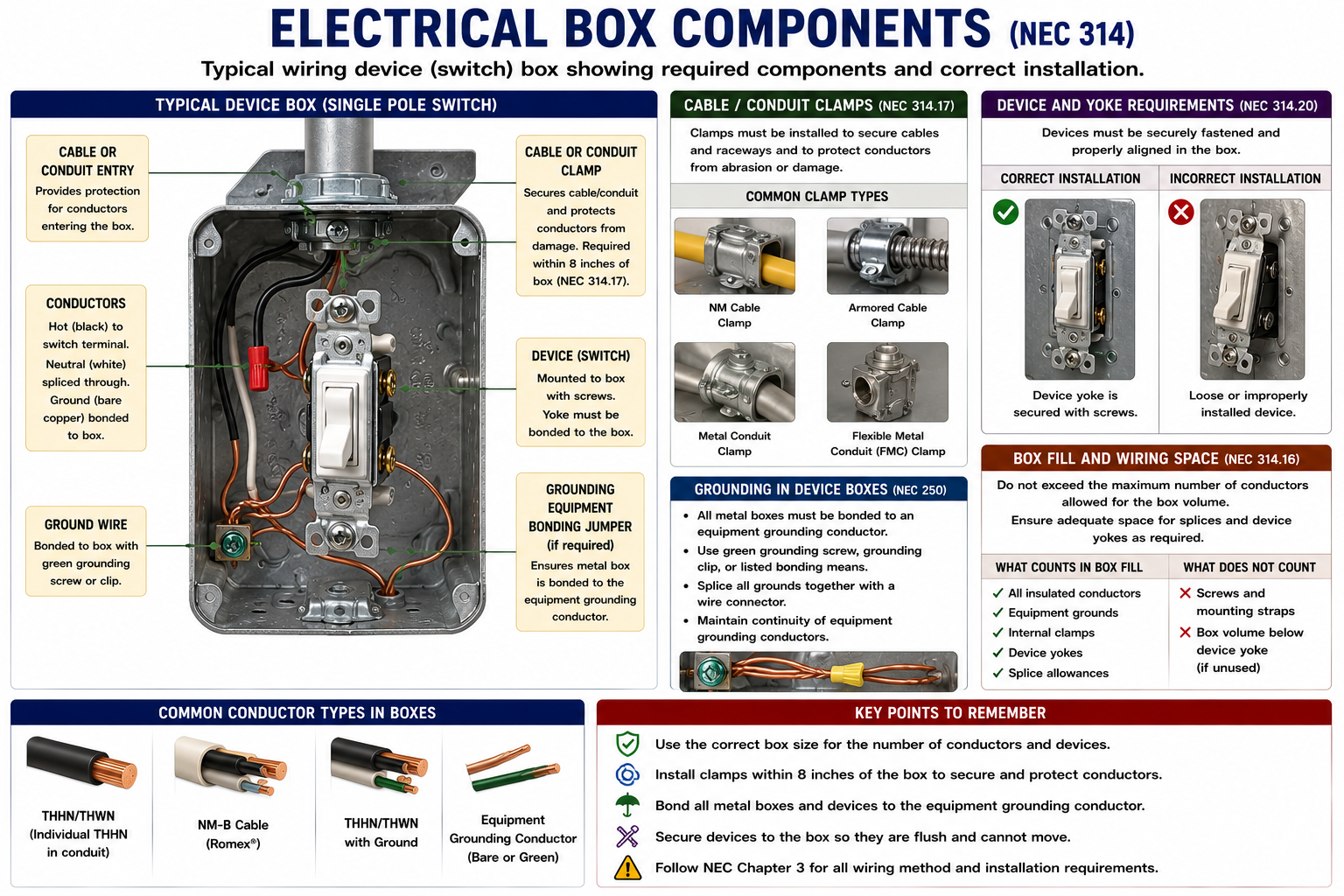
Electrical boxes, conduit bodies, cabinets, and enclosures provide protected locations for conductor terminations, splices, devices, wiring-method transitions, and equipment connections. Correct selection and installation are essential because these components must provide adequate space, protect conductors from damage, maintain grounding and bonding continuity, and remain suitable for the environment in which they are installed.
For the NASCLA Electrical Contractor Exam, you should understand the basic functions of electrical boxes and conduit bodies, conductor-entry requirements, cable and raceway connections, grounding and bonding, enclosure suitability, accessibility, box volume markings, and the components that will be counted during the box-fill calculations covered in Lesson 50.
Boxes Are More Than Containers
Electrical boxes and enclosures are part of the wiring system. They protect conductors and connections, provide locations for devices and equipment, terminate raceways and cables, and contain splices and taps where permitted.
Article 314 contains many of the NEC requirements for outlet boxes, device boxes, pull boxes, junction boxes, conduit bodies, fittings, and handhole enclosures. Related requirements in Articles 250 and 300 also affect grounding, bonding, conductor protection, wiring-method support, and accessibility.
What Article 314 Covers
Article 314 addresses a broad group of wiring-system enclosures and fittings. These components may look different, but each provides a controlled location where conductors, raceways, cables, devices, or connections are contained and protected.
Outlet Boxes
Provide locations where electrical utilization equipment such as luminaires or receptacles is connected to the wiring system.
Device Boxes
Provide mounting and wiring space for switches, receptacles, controls, and similar devices.
Junction Boxes
Provide protected locations for conductor splices, taps, and wiring-method transitions.
Pull Boxes
Provide accessible pulling points in raceway systems and are particularly important in installations involving larger conductors or complex raceway layouts.
Conduit Bodies
Provide access to raceway systems for pulling, changing direction, and, where specifically permitted and properly sized, splicing or tapping conductors.
Handhole Enclosures
Provide access to underground wiring systems and are subject to requirements appropriate to their environment and use.
A Box Must Be Large Enough for What Is Inside It
An electrical box cannot be selected simply because the conductors and device physically fit inside. Article 314 establishes minimum volume requirements based on the conductors, grounding conductors, clamps, devices, and other components occupying the enclosure.
Lesson 50 develops the actual calculation procedure. In this lesson, focus on recognizing which components are present and why they matter.
What Electrical Boxes Accomplish
Contain Connections
Boxes provide protected locations for splices, taps, conductor terminations, and device connections.
Terminate Wiring Methods
Raceways and cables commonly terminate at boxes using connectors, clamps, hubs, or other fittings suitable for the wiring method.
Support Devices
Boxes provide mounting points for switches, receptacles, luminaires, and other equipment when the box is designed and installed for that purpose.
Protect Conductors
The enclosure protects conductors and connections against physical damage and reduces exposure to surrounding building materials and environmental conditions.
Protect Conductors From Abrasion
NEC 314.17 requires conductors entering boxes, conduit bodies, or fittings to be protected from abrasion. Openings used for conductor entry must be appropriately closed, and raceways and cables must be secured to boxes or conduit bodies as required by the applicable wiring-method rules.
Sharp edges, improperly removed knockouts, damaged fittings, and poorly installed connectors can cut or abrade conductor insulation during installation or while the wiring system is in service.
Prepare the Opening
Use a knockout or opening appropriate for the wiring method and fitting being installed.
Install the Correct Fitting
Use a connector, hub, clamp, bushing, or other fitting identified for the cable or raceway.
Protect the Conductors
Ensure that conductor insulation cannot contact sharp edges or damaged surfaces at the enclosure entry.
Secure the Wiring Method
Secure the raceway or cable to the box as required by its wiring-method article and the applicable box provisions.
Close Open Knockouts and Openings
Unused openings in boxes and enclosures must be closed using an approved means appropriate for the enclosure. Leaving an unused knockout open can expose energized conductors, allow foreign material to enter, and compromise the environmental rating of the enclosure.
In wet, damp, dusty, corrosive, or other demanding environments, the closure must also preserve the degree of protection required for the enclosure.
Grounding and Bonding Metal Enclosures
Metal boxes and enclosures that are required to be grounded must be connected to the equipment grounding system so that exposed conductive parts cannot remain energized during a ground fault. Article 250 contains the grounding and bonding requirements that work together with Article 314.
When circuit conductors are spliced or terminated in a metal box, equipment grounding conductors must be arranged so the grounding connection to the box and to connected equipment remains effective even if a device is removed.
Metal Box
The enclosure must be connected to the equipment grounding path where grounding is required.
Equipment Grounding Conductors
Wire-type equipment grounding conductors entering the box are joined and connected as required to maintain continuity.
Metal Raceway
A qualifying metallic raceway can serve as part of the grounding path when properly installed and electrically continuous.
Devices
Switches, receptacles, and other devices requiring grounding must be connected to the equipment grounding system by an approved means.
Removing a Device Must Not Destroy Grounding Continuity
Equipment grounding conductors should not depend on a receptacle, switch, or other removable device to maintain continuity through the box. Grounding and bonding connections must remain effective when the device is removed for service.
This principle is especially important in boxes containing multiple equipment grounding conductors or downstream circuits.
Grounding Requirements Still Apply to Equipment
A nonmetallic box itself does not require bonding in the same manner as a metal enclosure because the box is not conductive. However, equipment grounding conductors must still be connected to receptacles, switches, luminaires, or other equipment that requires grounding.
If metallic wiring methods or conductive components are used with a nonmetallic box, the installation must provide the grounding and bonding required for those components.
Cable Clamps Occupy Box Space
Some boxes include internal cable clamps as part of the enclosure. These clamps secure cables where they enter the box and protect the cable from being pulled or displaced.
Internal clamps can affect box-fill calculations because they occupy usable box volume. External clamps located outside the box do not occupy interior volume in the same manner.
Internal Clamp
Located within the box and considered when determining the required box volume under the applicable box-fill rules.
External Clamp
Located outside the interior wiring space and therefore does not occupy the same interior box volume.
Switches and Receptacles Use Box Volume
A switch, receptacle, control, or similar device mounted in a box occupies space. The metal strap or mounting frame of the device is commonly called the device yoke.
Device yokes are specifically considered during box-fill calculations because the device and connected conductors occupy usable wiring space. Lesson 50 explains how the conductor-size-based volume allowance for each yoke is determined.
Equipment Grounding Conductors Also Affect Box Fill
Equipment grounding conductors and bonding jumpers occupy space within a box and must be included in the box-fill calculation using the rules of 314.16(B).
The current rules do not simply count every equipment grounding conductor as one full conductor volume. The calculation method accounts for groups of equipment grounding conductors and additional conductors according to the specific provisions of 314.16(B)(5), which will be applied in Lesson 50.
Learn to Identify Everything Inside the Box
Before performing arithmetic, make an inventory of the contents: insulated conductors, pass-through conductors, equipment grounding conductors, bonding jumpers, internal clamps, device yokes, and any other components that receive a volume allowance.
Most box-fill errors begin with counting the contents incorrectly rather than with multiplying the volume allowances incorrectly.
Where Box Capacity Comes From
NEC 314.16(A) establishes how box volume is determined. Standard metal boxes described by Table 314.16(A) can use the volume assigned by the table. Other boxes of the sizes covered by the marking rule, including nonmetallic boxes, are generally marked by the manufacturer with their volume.
Extension rings, plaster rings, domed covers, and similar components can add usable volume when they are marked with their volume or otherwise qualify under 314.16(A).
Standard Metal Box
Use Table 314.16(A) when the standard box dimensions correspond to a listed table entry and no larger marked volume applies.
Marked Box
Use the manufacturer’s durable volume marking where Article 314 requires or permits the box capacity to be marked.
Extension Components
Qualifying extension rings, plaster rings, covers, and similar components can contribute additional volume.
Required Volume
The available box volume must not be less than the total volume required for the conductors and other contents.
LBs, LRs, LLs, Ts, and Other Conduit Bodies
Conduit bodies are fittings that provide access to conductors within a raceway system. Common forms include LB, LL, LR, T, and C configurations. They are frequently used where the raceway changes direction or where access is needed for conductor pulling.
A conduit body should not automatically be treated as a junction box. Whether splices, taps, or devices are permitted depends on the conduit body’s construction, marking, volume, and compliance with the applicable Article 314 requirements.
LB
Provides a 90-degree change of direction with the removable cover generally located on the back of the bend.
LL and LR
Provide side-access configurations selected according to the orientation needed for the installation.
T Body
Allows raceways to enter from three directions and can provide access to conductors at the junction.
C Body
Provides straight-through conductor access without changing the direction of the raceway.
A Conduit Body Is Not Automatically Approved for Splices
Conduit bodies containing splices, taps, or devices must meet the applicable Article 314 volume and marking requirements. Some short-radius conduit bodies are intended only to assist in installation of the raceway and conductors and cannot contain splices, taps, or devices.
When an exam problem mentions an LB or another conduit body containing splices, determine whether the conduit body is marked and sized for that use before assuming the installation is permitted.
Boxes Must Be Suitable for the Location
Boxes and enclosures must be selected for the conditions in which they are installed. A box suitable for a dry interior wall is not automatically suitable for outdoor, wet, corrosive, hazardous, or underground use.
Dry Locations
Standard interior boxes are commonly used where moisture and weather exposure are not concerns.
Damp Locations
Boxes, fittings, and covers must be selected and installed to prevent moisture from entering or accumulating where the Code requires such protection.
Wet Locations
Boxes and associated components installed in wet locations must be listed or identified for the environment and installed so the required protection is maintained.
Corrosive Locations
Materials and coatings must be suitable for chemicals, moisture, salts, or other corrosive influences present at the installation.
Prevent Moisture From Accumulating
Article 314 contains requirements for boxes, conduit bodies, and fittings installed in damp or wet locations. The installation must prevent moisture from entering or accumulating where required, and components used in wet locations must be suitable for wet-location service. :contentReference[oaicite:1]{index=1}
Maintaining the enclosure rating requires more than choosing the correct box. Covers, hubs, connectors, gaskets, plugs, fittings, and mounting orientation can all affect the completed installation.
Boxes and Finished Surfaces
Flush-mounted boxes must be installed with proper relationship to the finished wall or ceiling surface. The permissible setback depends on whether the surrounding surface is combustible or noncombustible.
Where a box is set too far behind the finished surface, an approved extension or other corrective method may be necessary. The objective is to prevent exposed combustible material and maintain proper enclosure of wiring and devices.
Boxes Must Be Securely Mounted
Boxes must be supported using methods permitted by Article 314.23. Depending on the installation, a box may be supported from structural members, brackets, framing systems, raceways under specific permitted conditions, or other approved means.
The wiring conductors themselves are not intended to support the box. A box must remain securely positioned during device operation, conductor pulling, servicing, and normal use.
The Box Must Be Suitable for the Load
Boxes used to support luminaires, ceiling-suspended equipment, ceiling fans, or other equipment must be designed or identified for the load being supported. A standard device or outlet box should not be assumed capable of supporting every piece of equipment that can physically be attached to it.
Article 314.27 contains specific requirements for outlet boxes used to support luminaires, lampholders, ceiling-suspended fans, and related equipment.
Fan Support Requires the Correct Box
A ceiling fan imposes both weight and dynamic forces on its support. A standard luminaire outlet box is not automatically suitable for supporting a ceiling-suspended paddle fan.
If an exam question identifies a ceiling fan or similar load, look for the specific Article 314.27 requirements rather than assuming any ceiling box is acceptable.
Completed Boxes Need Proper Closure
In a completed installation, boxes generally require an appropriate cover, faceplate, luminaire canopy, lampholder, or other permitted closure. An open junction box with exposed internal wiring is not a completed installation.
The cover must be suitable for the box and environment. Where metallic covers or plates require grounding, the applicable Article 250 grounding provisions must also be satisfied. :contentReference[oaicite:2]{index=2}
Splices and Pull Points Must Remain Accessible
Boxes and conduit bodies containing wiring that requires access cannot simply be buried behind permanent building finishes. Junction boxes and pull points must remain accessible as required by the NEC.
A removable ceiling panel can provide access where permitted, while drywalling permanently over a junction box ordinarily does not. Accessibility allows inspection, testing, repair, conductor replacement, and future maintenance.
Do Not Bury a Junction Box
A splice cannot be made in a box and then permanently concealed behind drywall merely because the splice was compliant when originally installed. Where the NEC requires the box to remain accessible, the completed building must preserve that access.
Leave Sufficient Free Conductor
Conductors at outlet, junction, and switch points must have sufficient free length for splicing and connection. Article 300.14 contains the general free-conductor requirements used with boxes and enclosures.
A box can have adequate cubic-inch volume and still be poorly installed if the conductors are cut too short to allow safe connection or servicing.
4 AWG and Larger Change the Rules
The familiar box-fill rules of 314.16 are primarily associated with conductors 6 AWG and smaller. Boxes and conduit bodies containing conductors 4 AWG and larger are also subject to the dimensional requirements of 314.28.
Those larger-conductor pull-box and junction-box requirements are covered in detail in Lesson 52. They are based on raceway arrangement and conductor-pulling space rather than simply adding cubic-inch conductor allowances.
314.16 vs. 314.28
When an exam question involves ordinary device or junction boxes with smaller conductors, box volume calculations under 314.16 are usually the focus. When conductors 4 AWG or larger are involved, check 314.28 for pull-box and junction-box sizing requirements.
Recognizing the conductor size can tell you which calculation method the question expects.
What You Will Count in Lesson 50
Before moving into the actual calculations, learn to recognize the different items that can create a box-volume allowance.
Insulated Conductors
Conductors entering, leaving, passing through, terminating, or being spliced in the box are evaluated according to the box-fill rules.
Equipment Grounding Conductors
Equipment grounding conductors and bonding jumpers receive allowances according to the specific grounding-conductor rule.
Internal Cable Clamps
Internal clamps can require a volume allowance because they occupy usable wiring space.
Device Yokes
Switches, receptacles, and similar devices mounted on yokes receive volume allowances based on the conductor size connected to the device.
Barriers
Where a box contains barriers, the available space and required calculations can be affected by the way the enclosure is divided.
Box Capacity
The final required volume is compared with the available volume of the selected box and qualifying extension components.
Analyze the Box Before Calculating
Box questions can combine wiring methods, grounding, device support, environmental suitability, accessibility, and fill requirements. Work through the installation logically before performing any arithmetic.
Identify the Enclosure
Determine whether the question involves an outlet box, device box, junction box, pull box, conduit body, cabinet, or another enclosure.
Identify the Environment
Determine whether the enclosure is installed in a dry, damp, wet, corrosive, underground, hazardous, or other special location.
Identify the Wiring Methods
Determine which cables or raceways enter the enclosure and whether the fittings are appropriate.
Check Grounding and Bonding
Determine whether metal boxes, devices, raceways, and equipment are properly connected to the equipment grounding system.
Inventory the Contents
Identify conductors, grounding conductors, clamps, devices, yokes, barriers, and other components affecting available space.
Select the Correct Sizing Rule
Use 314.16 for applicable box-volume calculations and 314.28 when larger conductors require pull-box or junction-box dimensions.
Article 314 Contains Several Different Types of Questions
Do not assume every Article 314 question is a box-fill problem. The exam may instead test conductor entries, environmental suitability, accessibility, box support, cover requirements, luminaire or fan support, or large-conductor pulling space.
Identify what the question is actually asking before turning directly to 314.16.
Code Locations to Know
Article 314
Outlet, device, pull, and junction boxes; conduit bodies; fittings; and handhole enclosures.
314.15
Requirements affecting boxes and conduit bodies in damp and wet locations.
314.16
Box and conduit-body volume requirements and the box-fill rules developed in Lesson 50.
314.17
Requirements for conductors and cables entering boxes, conduit bodies, and fittings.
314.20
Requirements affecting flush-mounted boxes and finished surfaces.
314.23
Methods for supporting boxes and enclosures.
314.25
Requirements for covers, faceplates, canopies, and completed box closure.
314.27
Outlet-box requirements related to supporting luminaires, lampholders, fans, and similar equipment.
314.28
Pull-box and junction-box requirements for conductors 4 AWG and larger.
314.29
Accessibility requirements affecting boxes, conduit bodies, and handhole enclosures.
250.148
Continuity and connection of equipment grounding conductors within boxes.
300.14
Minimum free-conductor length at outlets, junctions, and switch points.
Key Points to Remember
- Article 314 covers outlet boxes, device boxes, pull boxes, junction boxes, conduit bodies, fittings, and handhole enclosures.
- Boxes provide protected locations for splices, taps, devices, conductor terminations, and wiring-method transitions.
- Conductors entering boxes and conduit bodies must be protected from abrasion.
- Raceways and cables must be secured to boxes and conduit bodies as required by the applicable rules.
- Unused enclosure openings must be properly closed.
- Metal boxes must be properly grounded and bonded where grounding is required.
- Removing a device must not interrupt required equipment-grounding continuity.
- Nonmetallic boxes do not eliminate the grounding requirements for devices and other conductive equipment.
- Internal cable clamps can affect required box volume.
- Switches, receptacles, and other device yokes occupy box volume.
- Equipment grounding conductors and bonding jumpers receive box-fill allowances under the specific rules of 314.16(B).
- Box capacity can come from Table 314.16(A), a manufacturer volume marking, and qualifying extension components.
- A conduit body is not automatically permitted to contain splices or taps.
- Boxes, fittings, covers, and connectors must be suitable for wet, damp, corrosive, and other environmental conditions.
- Boxes must be securely supported.
- Boxes used to support luminaires, fans, or other loads must be suitable for that purpose.
- Completed boxes require the appropriate cover, faceplate, canopy, or other permitted closure.
- Junction boxes and required pull points must remain accessible.
- 314.16 addresses applicable box-volume calculations, while 314.28 establishes requirements for boxes containing conductors 4 AWG and larger.
- Before calculating box fill, first identify every conductor, grounding conductor, clamp, device yoke, and other component inside the box.
Leave a Reply
You must be logged in to post a comment.