Back to: NASCLA Master Electrical Contractor Exam Preparation
The ampacity shown in an NEC conductor table is based on specific installation conditions. When conductors operate in higher ambient temperatures or when more than three current-carrying conductors are installed together under conditions addressed by Article 310, the allowable conductor ampacity may have to be reduced.
For the NASCLA Electrical Contractor Exam, you should be able to recognize when temperature correction or conductor adjustment is required, locate the appropriate NEC tables, determine the correct factor, and apply that factor without confusing conductor insulation ratings with equipment termination limitations.
Why Ampacity Must Sometimes Be Modified
Electrical conductors generate heat as current flows through them. The allowable ampacities in NEC tables are based on stated conditions of use. When the surrounding temperature increases or additional current-carrying conductors are grouped together, the conductors may not be able to dissipate heat as effectively.
Article 310 addresses these conditions through temperature correction factors and ampacity adjustment factors. These are related calculations, but they address different causes of conductor heating and should not be confused with one another.
Correction vs. Adjustment
The terms correction and adjustment refer to different conditions. Keeping these concepts separate makes NEC calculation questions much easier to solve.
Temperature Correction
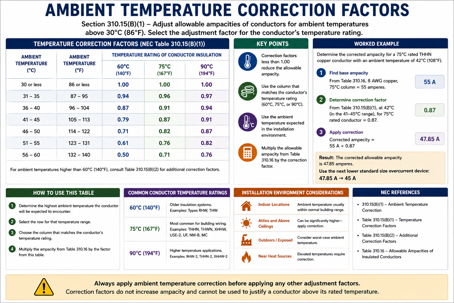
Temperature correction addresses ambient temperatures that differ from the temperature basis of the applicable ampacity table. Higher surrounding temperatures generally reduce the conductor’s allowable ampacity.
Ampacity Adjustment
Ampacity adjustment addresses conditions such as having more than three current-carrying conductors installed together in a raceway, cable, or other condition covered by the applicable NEC rule.
A conductor installation can require temperature correction, conductor adjustment, both calculations, or neither calculation. The conditions described in the exam question determine which rules apply.
Ambient Temperature
Conductor ampacity depends partly on the conductor’s ability to transfer heat to its surroundings. As ambient temperature increases, the temperature difference between the conductor and its surroundings decreases, making heat dissipation more difficult.
For ampacity tables based on an ambient temperature of 30°C (86°F), Table 310.15(B)(1)(1) provides correction factors for other ambient temperatures. The applicable factor depends on both the ambient temperature and the temperature rating of the conductor.
Determine the Ambient Temperature
Identify the temperature of the environment through which the conductors will operate. Exam questions normally provide this information when a temperature correction calculation is required.
Identify the Conductor Temperature Rating
Determine the insulation temperature rating of the conductor so that the appropriate correction-factor column can be selected.
Locate the Correction Factor
Use the appropriate ambient-temperature correction table and locate the factor corresponding to the ambient-temperature range and conductor temperature rating.
Multiply the Ampacity
Multiply the applicable conductor ampacity by the correction factor to determine the corrected ampacity.
Applying an Ambient Temperature Correction Factor
Suppose a conductor with 90°C-rated insulation has an applicable table ampacity of 100 amperes before correction and is installed where the ambient temperature is 40°C (104°F). Table 310.15(B)(1)(1) provides a correction factor of 0.91 for a 90°C conductor at that ambient temperature.
Corrected Ampacity
100 A × 0.91 = 91 A
The corrected ampacity is therefore 91 amperes before considering any other applicable adjustment, equipment termination limitation, or circuit-specific requirement.
Use the Conductor Insulation Rating for Correction and Adjustment
When permitted by the NEC, temperature correction and ampacity adjustment calculations are based on the conductor’s insulation temperature rating. This is why a conductor with 90°C insulation can provide an advantage even when the equipment termination is rated only 75°C.
The corrected or adjusted result must still comply with the applicable equipment termination temperature limitation. Using the 90°C ampacity as the starting point for a permitted correction or adjustment calculation does not mean that a 75°C termination suddenly becomes a 90°C termination.
More Than Three Current-Carrying Conductors
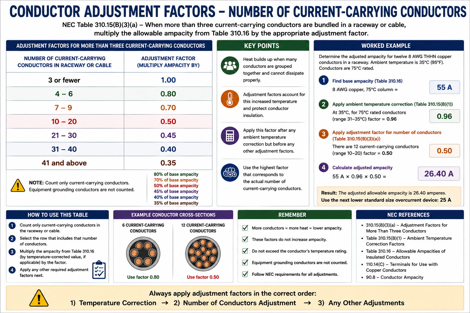
Conductors carrying current produce heat. When multiple current-carrying conductors are grouped together, each conductor contributes heat while the surrounding conductors and wiring method can restrict heat dissipation. Article 310 therefore requires ampacity adjustment under specified conditions when the number of current-carrying conductors exceeds three.
4–6 Conductors
80% of the applicable ampacity.
7–9 Conductors
70% of the applicable ampacity.
10–20 Conductors
50% of the applicable ampacity.
21–30 Conductors
45% of the applicable ampacity.
31–40 Conductors
40% of the applicable ampacity.
41 or More Conductors
35% of the applicable ampacity.
Applying a Current-Carrying-Conductor Adjustment
Suppose a 90°C-rated conductor has an ampacity of 100 amperes from the applicable ampacity table and six current-carrying conductors are installed together under conditions requiring Table 310.15(C)(1) adjustment.
Six current-carrying conductors fall within the 4–6 conductor range, so the applicable adjustment factor is 80 percent.
Adjusted Ampacity
100 A × 0.80 = 80 A
The adjusted conductor ampacity is therefore 80 amperes before considering any other applicable limitations.
When Both Correction and Adjustment Apply
Some installations require both ambient-temperature correction and current-carrying-conductor adjustment. When both apply, both factors must be included in the ampacity calculation.
The basic calculation can be expressed as:
Combined Ampacity Calculation
Adjusted Ampacity = Table Ampacity × Temperature Correction Factor × Conductor Adjustment Factor
For example, assume a 90°C-rated conductor has a table ampacity of 100 amperes, the applicable ambient-temperature correction factor is 0.91, and the applicable current-carrying-conductor adjustment factor is 0.80.
Example
100 A × 0.91 × 0.80 = 72.8 A
The resulting ampacity after both factors are applied is 72.8 amperes. The installation must then be checked against the applicable equipment termination temperature limitations and all other relevant NEC requirements.
Which Conductors Are Current-Carrying?
Determining the adjustment factor requires correctly counting the current-carrying conductors. Do not assume that every conductor physically present in a raceway or cable is automatically counted in exactly the same manner.
Ungrounded Conductors
Phase and line conductors carrying load current are normally counted as current-carrying conductors.
Neutral Conductors
Whether a neutral is counted depends on how it carries current and the circuit configuration. NEC 310.15(E) contains the rules for determining when neutral conductors are considered current carrying for adjustment purposes.
Equipment Grounding Conductors
Equipment grounding and bonding conductors are not counted as current-carrying conductors for the adjustment-factor calculation.
Spare Conductors
Spare conductors can affect the count under the applicable Table 310.15(C)(1) provisions. Read the table notes and the conditions in the problem rather than assuming an unused conductor can always be ignored.
The Neutral Does Not Always Count the Same Way
Neutral-conductor questions are a common source of errors because the neutral may or may not be considered current carrying depending on the circuit.
For example, the neutral of a 3-wire, single-phase 120/240-volt circuit carries only the imbalance of the other conductors and is not counted as a current-carrying conductor for this adjustment. Other circuit configurations can require the neutral to be counted, particularly where it carries current in addition to only the imbalance or where nonlinear loads create significant harmonic neutral current.
On an exam question, identify the electrical system and load characteristics before deciding whether the neutral contributes to the current-carrying-conductor count.
Do Not Automatically Count Every Wire in the Raceway
A raceway containing three phase conductors, a neutral conductor, and an equipment grounding conductor does not automatically contain five current-carrying conductors. The equipment grounding conductor is not current carrying for this calculation, and the neutral must be evaluated under the applicable NEC rules.
The exam may intentionally include grounding conductors or neutral conductors in a raceway diagram to test whether you know which conductors actually belong in the adjustment-factor count.
Solving Ampacity Adjustment Problems
Determine the Required Load Ampacity
Establish the ampacity the conductor must ultimately be capable of carrying under the applicable circuit rules.
Identify Conductor Type and Temperature Rating
Determine the conductor material, insulation type, and insulation temperature rating.
Determine Ambient Temperature
If temperature correction is required, locate the appropriate correction factor in Table 310.15(B)(1)(1) or other applicable table.
Count Current-Carrying Conductors
Apply the rules for phase conductors, neutrals, equipment grounding conductors, and any other conductors involved.
Determine the Adjustment Factor
If more than three current-carrying conductors are present under conditions requiring adjustment, obtain the applicable factor from Table 310.15(C)(1).
Apply the Required Factors
Multiply the applicable table ampacity by the temperature correction factor and adjustment factor as required.
Check Termination Limitations
Verify that the resulting conductor selection also complies with the applicable equipment termination temperature requirements.
Work Backward When Necessary
Some exam questions provide a required load ampacity and ask you to determine the minimum conductor size after correction and adjustment. In those problems, it can be faster to divide the required ampacity by the applicable factors to determine the minimum table ampacity needed before the factors are applied.
For example, if a conductor must provide at least 80 amperes after an 80 percent adjustment, the conductor must have a pre-adjustment ampacity of at least 80 ÷ 0.80 = 100 amperes. If both correction and adjustment factors apply, divide by the product of both factors and then select a conductor having at least that pre-adjustment ampacity.
Code Locations to Know
310.15(B)
Contains ambient-temperature correction provisions associated with conductor ampacity.
Table 310.15(B)(1)(1)
Provides ambient-temperature correction factors associated with ampacity tables based on 30°C (86°F).
310.15(C)
Contains conductor ampacity adjustment provisions for applicable installation conditions.
Table 310.15(C)(1)
Provides adjustment factors where more than three current-carrying conductors are installed under the conditions addressed by the rule.
310.15(E)
Addresses when neutral conductors are considered current carrying for ampacity adjustment.
310.15(F)
Establishes that equipment grounding and bonding conductors are not considered current carrying for these adjustment calculations.
Key Points to Remember
- Temperature correction and conductor adjustment are two different ampacity modifications.
- Ambient temperature can require a correction factor because it affects the conductor’s ability to dissipate heat.
- Table 310.15(B)(1)(1) provides ambient-temperature correction factors for ampacity tables based on 30°C (86°F).
- More than three current-carrying conductors can require ampacity adjustment under the applicable Article 310 conditions.
- Table 310.15(C)(1) uses 80% for 4–6 conductors, 70% for 7–9, 50% for 10–20, 45% for 21–30, 40% for 31–40, and 35% for 41 or more.
- When both correction and adjustment apply, both factors must be included in the calculation.
- Permitted correction and adjustment calculations can begin with the conductor insulation temperature rating, but the final conductor selection must still comply with equipment termination temperature limitations.
- Equipment grounding and bonding conductors are not counted as current-carrying conductors for this adjustment.
- Neutral conductors must be evaluated according to the circuit configuration and NEC 310.15(E).
- Do not count conductors or select factors from memory without first identifying the exact installation conditions described in the exam question.
Leave a Reply
You must be logged in to post a comment.