Back to: NASCLA Master Electrical Contractor Exam Preparation
Selecting the correct conductor requires more than matching a wire size to an amperage value. Conductor material, conductor size, insulation temperature rating, equipment termination ratings, ambient temperature, and installation conditions can all affect the allowable ampacity of a conductor.
For the NASCLA Electrical Contractor Exam, you should be able to identify the appropriate NEC conductor requirements, navigate the ampacity tables efficiently, and recognize when additional correction, adjustment, or equipment-specific requirements must be considered.
Understanding Conductor Ampacity
Ampacity is the maximum current, in amperes, that a conductor can carry continuously under its conditions of use without exceeding its temperature rating. The important phrase is under its conditions of use. A conductor does not have one universally applicable ampacity regardless of how or where it is installed.
The NEC conductor rules are found primarily in Article 310, while other articles modify or supplement those requirements for particular circuits, equipment, wiring methods, and applications. Successful exam navigation therefore requires knowing both where the basic ampacity information is located and when another Code rule may affect the final conductor selection.
What Determines a Conductor’s Ampacity?
Conductor ampacity is affected by the conductor itself and by the environment in which it operates. Current flowing through a conductor produces heat because of conductor resistance. The installation must allow the conductor to carry the required current without producing temperatures that exceed the limits of the conductor insulation, terminations, equipment, or other applicable components.
Conductor Material
Copper and aluminum have different electrical properties. NEC ampacity tables therefore provide separate ampacity values for copper and for aluminum or copper-clad aluminum conductors.
Conductor Size
Increasing conductor cross-sectional area generally reduces resistance and increases current-carrying capability. Conductors are identified using AWG sizes and, for larger conductors, circular-mil sizes expressed in kcmil.
Insulation Rating
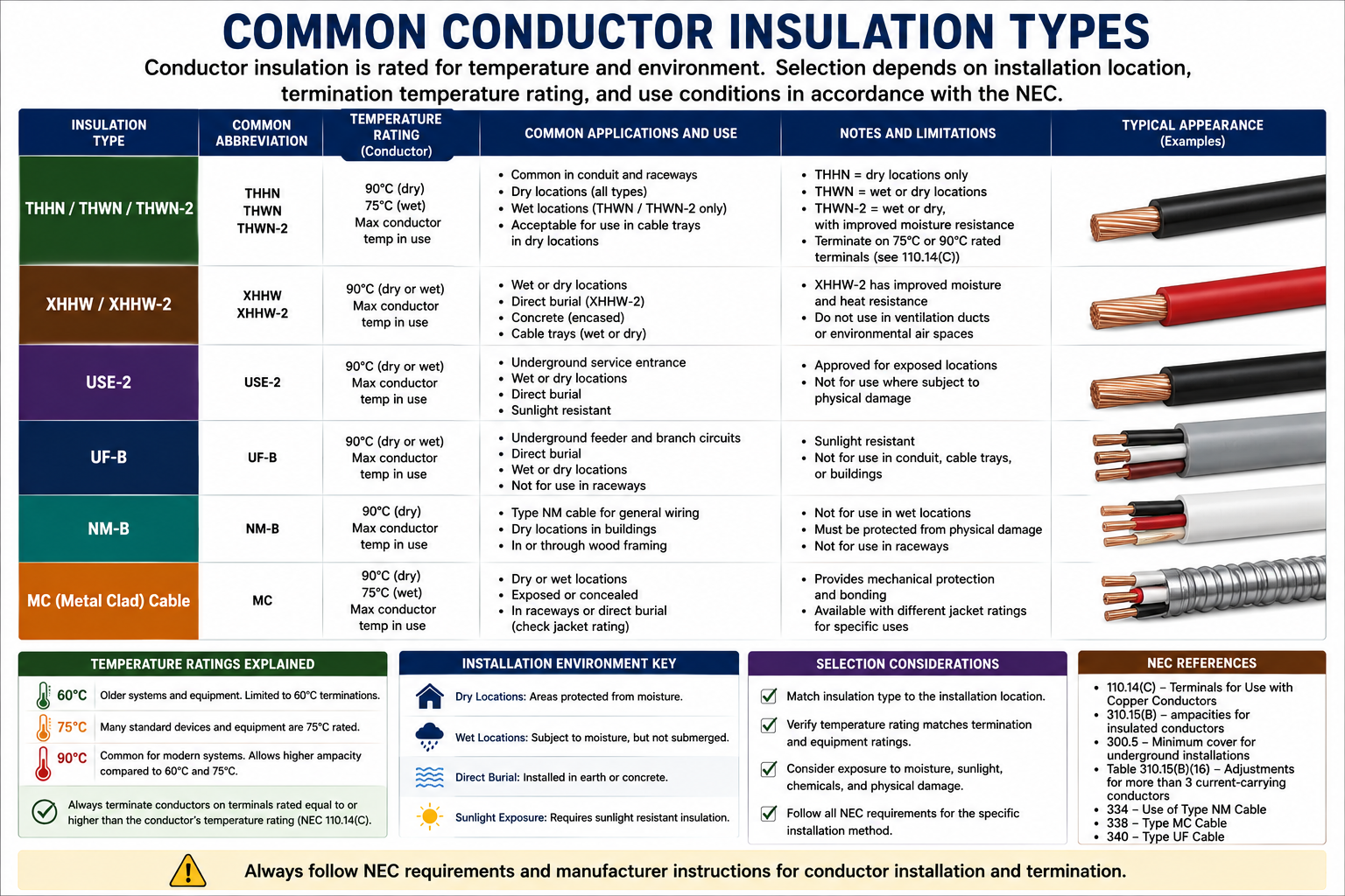
Conductor insulation types have temperature and environmental ratings. The applicable insulation rating affects which ampacity-table temperature column may be used as part of the conductor-sizing process.
Installation Conditions
Ambient temperature, the number of current-carrying conductors installed together, wiring method, and other conditions can require modification of the table ampacity.
AWG and kcmil
The American Wire Gauge system is commonly used for smaller electrical conductors. One characteristic of AWG numbering is that the relationship appears backward at first: as the AWG number becomes smaller, the conductor becomes larger. A 10 AWG conductor is therefore larger than a 12 AWG conductor, and a 6 AWG conductor is larger than an 8 AWG conductor.
After 1 AWG, conductor sizes continue through 1/0, 2/0, 3/0, and 4/0 AWG. Larger conductors are commonly designated in thousands of circular mils, abbreviated kcmil. Examples include 250 kcmil, 350 kcmil, 500 kcmil, and larger sizes.
Identify the Required Circuit Ampacity
Determine the load and any applicable requirements that establish the minimum conductor ampacity.
Identify Conductor Material
Determine whether the installation uses copper, aluminum, or another permitted conductor construction because the applicable table values differ.
Identify the Applicable Temperature Rating
Determine the conductor insulation rating and the temperature limitations imposed by equipment terminations and other applicable NEC requirements.
Use the Applicable Ampacity Table
Locate the conductor size that provides sufficient ampacity under the applicable conditions.
Check Conditions of Use
Determine whether ambient temperature, conductor bundling, installation conditions, or another NEC requirement modifies the allowable ampacity.
Using Table 310.16
Table 310.16 is one of the most important tables for conductor questions. It provides allowable ampacities for insulated conductors based on conductor size, conductor material, and conductor temperature rating under the conditions specified by the NEC.
The table is divided into columns for copper conductors and aluminum or copper-clad aluminum conductors. Within those groups are temperature-rating columns of 60°C, 75°C, and 90°C. Selecting a value from the table therefore requires more information than simply knowing the conductor size.
60°C Column
Used where the applicable conductor and termination requirements limit the installation to the 60°C ampacity.
75°C Column
Commonly applicable where conductors and equipment terminations are properly rated for 75°C operation.
90°C Column
Often important when using 90°C-rated conductors for permitted ampacity correction or adjustment calculations. A 90°C conductor rating does not by itself establish that equipment terminations may be loaded using the 90°C table ampacity.
Conductor Temperature Rating vs. Termination Rating
One of the most important conductor-sizing concepts is the distinction between the insulation temperature rating of the conductor and the allowable temperature rating of the equipment termination. A conductor may have 90°C-rated insulation while the equipment to which it connects has terminals that limit the allowable ampacity to a lower temperature column.
NEC 110.14(C) establishes temperature limitations associated with equipment terminations. Therefore, you cannot simply find a 90°C-rated conductor, select its ampacity from the 90°C column, and assume that value is permitted for the completed circuit.
Higher conductor temperature ratings remain useful because the NEC permits the conductor’s insulation temperature rating to be used when applying applicable correction and adjustment factors, provided the final allowable ampacity complies with the applicable termination limitations.
Table Ampacity May Not Be the Final Ampacity
A value obtained from an ampacity table is often the beginning of the conductor-sizing process rather than the end. Installation conditions can change the amount of heat a conductor can safely dissipate.
Ambient Temperature
Higher ambient temperatures can reduce the conductor’s ability to dissipate heat and may require temperature correction.
Current-Carrying Conductors
Installing multiple current-carrying conductors together can increase accumulated heat and may require an ampacity adjustment.
Termination Limitations
Equipment terminal ratings can limit the ampacity that may ultimately be assigned to the conductor.
Special Applications
Motors, transformers, services, feeders, dwelling installations, and other applications may have additional conductor-sizing provisions elsewhere in the NEC.
Lesson 42 examines temperature correction and current-carrying-conductor adjustment factors in detail. For this lesson, remember that a table value should never be assumed to be the final allowable ampacity until the conductor’s conditions of use have been evaluated.
Do Not Size Conductors From Memory Alone
Experienced electricians often remember common conductor sizes and ampacities, but an open-book examination can deliberately introduce a condition that makes the familiar answer incorrect. A different conductor material, temperature rating, ambient temperature, number of current-carrying conductors, or termination rating can change the result.
Read the question carefully before opening the ampacity table. Identify the conductor material, insulation type, equipment rating, installation conditions, and any special application mentioned in the problem. Then use those facts to determine which NEC provisions and table columns apply.
What Is the Load?
Determine the required circuit or conductor ampacity from the information given.
Copper or Aluminum?
Immediately identify which side of the applicable ampacity table you need.
What Temperature Ratings Apply?
Check conductor insulation and equipment termination information instead of automatically selecting the highest temperature column.
Are There Special Conditions?
Look for ambient temperature, multiple current-carrying conductors, special equipment, or another condition that changes the normal calculation.
Verify the Final Selection
Confirm that the selected conductor satisfies all applicable requirements rather than stopping after finding the first ampacity value that exceeds the load.
90°C Insulation Does Not Automatically Mean 90°C Ampacity
Seeing THHN, THWN-2, XHHW-2, or another conductor with a 90°C rating may tempt you to immediately use the 90°C ampacity column as the final allowable ampacity. That can be incorrect. The conductor insulation rating, equipment termination rating, correction and adjustment requirements, and other applicable Code provisions must all be considered.
When a question provides terminal temperature information, treat that information as intentional. It is often the clue that determines which ampacity value ultimately controls the installation.
Code Locations to Know
For conductor and ampacity questions, become comfortable moving between NEC Article 310 and the general equipment-termination requirements in Article 110. Table 310.16 is a major reference point, but it should not be treated as an isolated table.
Article 310
Conductors for general wiring, including conductor construction, applications, ampacity requirements, and associated tables.
Table 310.16
A primary ampacity table for insulated conductors under its stated conditions of use.
110.14(C)
Temperature limitations associated with electrical connections and equipment terminations.
240.4
Protection of conductors against overcurrent, including rules and limitations that must be considered along with conductor ampacity.
Key Points to Remember
- Ampacity is based on the current a conductor can carry under its conditions of use without exceeding its temperature rating.
- Conductor material matters because copper and aluminum conductors have different ampacity values.
- In the AWG system, a smaller gauge number represents a larger conductor.
- Table 310.16 is a major NEC reference for general conductor ampacity questions.
- The 60°C, 75°C, and 90°C columns correspond to temperature ratings and cannot be selected arbitrarily.
- A conductor with 90°C insulation does not automatically permit using its 90°C ampacity as the final circuit ampacity.
- Equipment termination temperature limitations must be considered under NEC 110.14(C).
- Ambient temperature and multiple current-carrying conductors can require correction or adjustment of conductor ampacity.
- Special equipment and applications may modify the general conductor-sizing rules.
- On the exam, identify all conditions in the question before selecting an ampacity-table value.
Leave a Reply
You must be logged in to post a comment.