Back to: NASCLA Master Electrical Contractor Exam Preparation
Part II has developed the electrical relationships and calculation methods needed to solve many of the theory questions encountered on the NASCLA Electrical Contractor examination. The individual formulas are important, but exam success depends just as much on recognizing which relationship applies to the problem.
This lesson brings together Ohm’s Law, series and parallel circuits, AC power and power factor, single-phase and three-phase systems, transformers, motors, voltage drop, and load calculations into one systematic review. The emphasis is selecting the correct method, organizing known values, maintaining correct units, and checking whether the final answer is electrically reasonable.
Recognize the Problem Before Selecting the Formula
Calculation errors frequently begin before the calculator is used. A candidate sees familiar numbers, selects a familiar formula, and begins calculating without first identifying whether the problem involves resistance, power, three-phase relationships, transformer ratios, motor speed, voltage drop, or load calculations.
A better method is to identify what the question gives you, determine what it asks you to find, select the applicable electrical relationship, solve the equation, and then check the result against the physical behavior of the circuit.
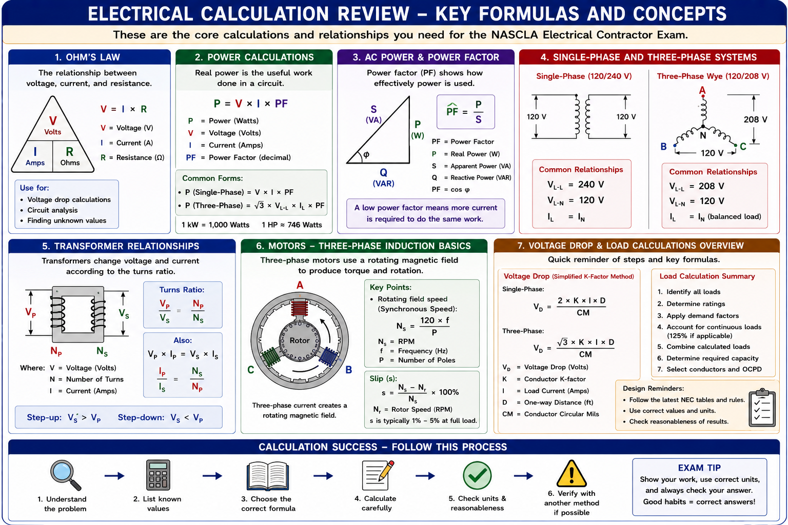
Use the Same Process for Every Calculation
Read the Entire Question
Determine what electrical system, equipment, or circuit the question describes before selecting a formula.
Identify the Unknown
Determine exactly what the question asks you to find: volts, amperes, ohms, watts, VA, power factor, RPM, conductor size, voltage drop, or another quantity.
List the Known Values
Write down the values given in the question and include their units.
Select the Relationship
Choose the formula or reference-book provision that connects the known quantities with the unknown quantity.
Rearrange Before Substituting
If necessary, rearrange the equation so the unknown is isolated before inserting numbers.
Calculate
Enter the values carefully and maintain consistent units throughout the calculation.
Check the Answer
Verify the units and ask whether the answer makes sense for the circuit or equipment described.
Voltage, Current, and Resistance
Ohm’s Law describes the relationship between voltage, current, and resistance. If two of these quantities are known, the third can be calculated directly.
Voltage
V = I × R
Current
I = V / R
Resistance
R = V / I
Quick check: At constant resistance, increasing voltage increases current. At constant voltage, increasing resistance decreases current.
Electrical Power Relationships
Electrical power can be calculated from voltage and current or by combining Ohm’s Law with the basic power relationship.
Voltage and Current
P = V × I
Current and Resistance
P = I2 × R
Voltage and Resistance
P = V2 / R
Select the power formula that uses the values already provided by the problem. This reduces unnecessary intermediate calculations and opportunities for error.
Current Is Common and Resistance Adds
Total Resistance
RT = R1 + R2 + R3 + …
Current
The same current flows through each component in a simple series circuit.
Voltage
The individual voltage drops add to the applied source voltage.
Reasonableness check: Total resistance in a series circuit must be greater than any individual resistance in that circuit.
Voltage Is Common and Current Divides
Reciprocal Relationship
1 / RT = 1 / R1 + 1 / R2 + 1 / R3 + …
Product-Over-Sum Shortcut
RT = (R1 × R2) / (R1 + R2)
Reasonableness check: Total resistance of a parallel network must be lower than the smallest individual branch resistance.
Use Conservation Relationships to Check Circuits
Kirchhoff’s Current Law
The algebraic sum of current entering and leaving a junction is zero. In practical terms, total current entering a node equals total current leaving it.
Kirchhoff’s Voltage Law
The algebraic sum of voltages around a closed circuit loop is zero. Source voltage and circuit voltage drops must balance.
Kirchhoff’s Laws provide useful checks for series, parallel, and combination-circuit calculations and can also support troubleshooting analysis.
Frequency, Period, Peak, and RMS Values
Frequency and Period
f = 1 / T and T = 1 / f.
Sinusoidal RMS Voltage
VRMS = Vpeak / √2
Sinusoidal Peak Voltage
Vpeak = VRMS × √2
A 60 Hz waveform has a period of approximately 16.67 milliseconds. A nominal 120 V sinusoidal AC system is normally expressed as an RMS value rather than its approximately 169.7 V peak value.
Real Power Is Only Part of AC Apparent Power
Apparent Power
S = VRMS × IRMS in a single-phase circuit.
Real Power
P = VRMS × IRMS × PF
Power Factor
PF = P / S
Sinusoidal Phase Relationship
For sinusoidal voltage and current, PF = cos φ.
Common error: Do not calculate watts as V × I for an AC load with a stated power factor less than 1.0. V × I gives apparent power in VA; multiply by power factor to determine real power in watts.
120/240 V Single-Phase, Three-Wire System
L1 to Neutral
Approximately 120 V.
L2 to Neutral
Approximately 120 V.
L1 to L2
Approximately 240 V.
System Type
This is a single-phase three-wire system, not a two-phase system.
120/208 V Three-Phase Wye System
Line to Neutral
Approximately 120 V.
Line to Line
Approximately 208 V.
Phase Displacement
The three phase voltages are displaced by 120 electrical degrees.
Wye Voltage Relationship
VLL = √3 × VLN
Remember the √3 Multiplier
Balanced Three-Phase
S = √3 × VLL × IL
Balanced Three-Phase
P = √3 × VLL × IL × PF
Exam point: Determine whether the problem is single-phase or three-phase before calculating power. The √3 multiplier is one of the most important clues distinguishing the two calculation methods.
Voltage Follows Turns and Current Changes Inversely
Voltage Ratio
VP / VS = NP / NS
Current Ratio
IP / IS = NS / NP
Ideal Power
VPIP = VSIS
Reasonableness check: A step-down transformer decreases voltage and increases available current in the ideal model. A step-up transformer increases voltage and decreases available current.
Frequency and Pole Count Determine Synchronous Speed
Motor Magnetic-Field Speed
NS = (120 × f) / P
Induction Motor
Slip (%) = [(NS − NR) / NS] × 100
2 Poles, 60 Hz
3,600 RPM synchronous speed.
4 Poles, 60 Hz
1,800 RPM synchronous speed.
6 Poles, 60 Hz
1,200 RPM synchronous speed.
8 Poles, 60 Hz
900 RPM synchronous speed.
A normal induction motor operating as a motor runs somewhat below synchronous speed because relative motion between the rotating magnetic field and rotor is necessary to induce rotor current and develop torque.
Identify Phase, Material, Current, Distance, and Conductor Area
Simplified K-Factor Formula
VD = (2 × K × I × D) / CM
Simplified K-Factor Formula
VD = (√3 × K × I × D) / CM
Uncoated Copper
A commonly used approximate K-factor at 75°C is 12.9.
Aluminum
A commonly used approximate K-factor at 75°C is 21.2.
Distance
D is the one-way distance when using the formulas shown above.
Conductor Area
CM represents conductor cross-sectional area in circular mils.
Percentage Voltage Drop
Percent VD = (VD / Vsource) × 100
Classification Comes Before Arithmetic
Load calculations require candidates to identify the load category and locate the applicable calculation provision before applying multipliers or demand factors.
Identify the Load
Determine whether the load involves lighting, receptacles, appliances, motors, HVAC equipment, heating equipment, or another category.
Locate the Applicable Rule
Use Article 220 and any equipment-specific NEC article referenced by the calculation.
Apply the Required Calculation
Apply unit loads, demand factors, continuous-load treatment, or other provisions only where the applicable rule requires or permits them.
Keep Compatible Units
Combine loads in compatible units such as VA before converting the final calculated load to current where required.
Match the Clue to the Calculation
Volts, Amperes, Ohms
Think Ohm’s Law.
Watts
Think electrical power relationships.
Watts and VA
Think power factor.
120/208 V Wye
Think √3 voltage relationships.
Turns and Winding Voltage
Think transformer ratio.
Frequency and Motor Poles
Think synchronous speed.
Distance and Conductor Size
Think voltage drop.
Lighting, Motors, HVAC, or Service Loads
Think NEC load-calculation provisions and reference navigation.
Ohm’s Law and Power
A 240 V resistive load draws 20 A. Determine its resistance and power.
Calculate Resistance
R = V / I = 240 / 20 = 12 ohms.
Calculate Power
P = V × I = 240 × 20 = 4,800 W.
Answer: Resistance is 12 ohms and power is 4.8 kW.
Three-Phase Power
A balanced three-phase load operates at 480 V line-to-line, draws 40 A, and has a power factor of 0.85. Determine the approximate real power.
Select the Formula
P = √3 × VLL × IL × PF.
Substitute
P = 1.732 × 480 × 40 × 0.85.
Calculate
P = approximately 28,267 W, or 28.3 kW.
Answer: The load uses approximately 28.3 kW of real power.
Transformer Ratio
An ideal transformer has a 600 V primary and a 120 V secondary. If the secondary supplies 25 A, determine the ideal primary current.
Determine the Voltage Ratio
600 / 120 = 5.
Apply the Inverse Current Ratio
IP = 25 / 5 = 5 A.
Check Power
600 V × 5 A = 3,000 VA and 120 V × 25 A = 3,000 VA.
Answer: The ideal primary current is 5 A.
Motor Speed and Slip
A four-pole induction motor operates at 60 Hz and has an actual loaded rotor speed of 1,740 RPM. Determine synchronous speed and percent slip.
Synchronous Speed
NS = (120 × 60) / 4 = 1,800 RPM.
Speed Difference
1,800 − 1,740 = 60 RPM.
Percent Slip
Slip = (60 / 1,800) × 100 = approximately 3.33%.
Answer: Synchronous speed is 1,800 RPM and motor slip is approximately 3.3%.
Use the Reference Books and Your Calculator Together
The NASCLA Electrical Contractor examination is open book, but open book does not eliminate the need to understand electrical theory. The reference material can provide formulas, tables, definitions, and Code provisions, but you must still recognize which material applies to the question.
Use the question to identify the topic, navigate directly to the relevant reference when necessary, write down the applicable relationship, and then use the calculator only after the problem has been organized.
Watch for These Mistakes Across Part II
Using the Wrong Formula
Identify the electrical relationship before inserting values.
Ignoring Units
Convert kW to W, kVA to VA, milliseconds to seconds, or other units when necessary before calculating.
Confusing Single-Phase and Three-Phase
Look for system voltage, phase designation, and whether √3 is required.
Reversing Ratios
Keep primary and secondary transformer quantities in corresponding positions.
Using Rotor RPM as Synchronous Speed
Induction-motor rotor speed is normally below synchronous speed during normal motoring operation.
Doubling Voltage-Drop Distance Twice
When using the single-phase 2KID/CM formula, D is already the one-way distance.
Applying a Demand Factor Without Authority
Use demand factors only where the applicable NEC provision permits them.
Accepting an Unreasonable Answer
Use basic circuit behavior to determine whether the result is physically plausible.
Part II Final Review
Question 1
A 24 ohm resistor is connected across 120 V. What current flows through it?
A. 2 A
B. 5 A
C. 12 A
D. 24 A
Question 2
Two resistors measuring 10 ohms and 15 ohms are connected in series. What is their total resistance?
A. 6 ohms
B. 12.5 ohms
C. 25 ohms
D. 150 ohms
Question 3
A load operates at 240 V, draws 10 A, and has a power factor of 0.80. What is its real power?
A. 1,920 W
B. 2,400 W
C. 3,000 W
D. 4,800 W
Question 4
What is the approximate line-to-line voltage of a balanced 120/208 V wye system when line-to-neutral voltage is 120 V?
A. 120 V
B. 169.7 V
C. 208 V
D. 240 V
Question 5
A transformer has 800 primary turns and 200 secondary turns. If the primary voltage is 480 V, what is the ideal secondary voltage?
A. 60 V
B. 120 V
C. 240 V
D. 1,920 V
Question 6
What is the synchronous speed of an eight-pole motor operating at 60 Hz?
A. 450 RPM
B. 900 RPM
C. 1,200 RPM
D. 1,800 RPM
Question 7
Which change will normally reduce conductor voltage drop when load current and circuit length remain unchanged?
A. Decrease conductor area.
B. Increase conductor area.
C. Increase conductor resistance.
D. Increase K-factor.
Question 8
A calculation requires a 48 A continuous load to be included at 125%. What is the calculated value of that portion?
A. 38.4 A
B. 48 A
C. 60 A
D. 96 A
Part II Final Review Answers
B — 5 A
I = V / R = 120 / 24 = 5 A.
C — 25 Ohms
Series resistances add directly: 10 + 15 = 25 ohms.
A — 1,920 W
P = V × I × PF = 240 × 10 × 0.80 = 1,920 W.
C — 208 V
VLL = √3 × VLN = 1.732 × 120 = approximately 208 V.
B — 120 V
VS = 480 × 200 / 800 = 120 V.
B — 900 RPM
NS = (120 × 60) / 8 = 900 RPM.
B — Increase Conductor Area
Increasing conductor cross-sectional area reduces resistance and therefore reduces voltage drop when other conditions remain unchanged.
C — 60 A
48 A × 1.25 = 60 A.
What You Should Take From Part II
Understand the Relationships
Formulas are easier to use correctly when you understand how voltage, current, resistance, power, frequency, phase, and equipment behavior relate to one another.
Identify the System
Determine whether the problem involves DC, single-phase AC, three-phase AC, transformers, motors, voltage drop, or load calculations before selecting the method.
Write Down Known Values
Organizing values and units before calculating reduces transcription and formula-selection errors.
Use √3 Carefully
The √3 relationship appears repeatedly in balanced three-phase voltage, power, transformer-current, and voltage-drop calculations.
Check Directional Relationships
Transformer voltage and current move in opposite directions, motor rotor speed remains below synchronous speed during normal induction-motor operation, and increasing conductor area reduces voltage drop.
Use the NEC When the Calculation Becomes Code-Based
Load calculations, conductor requirements, equipment sizing, and other Code-dependent questions require the applicable reference provision rather than a memorized general rule.
Check Every Final Answer
Confirm the units, magnitude, electrical behavior, and whether the answer actually addresses the quantity requested by the question.
Use the Open-Book Format Strategically
Know the theory well enough to recognize the problem, then use the approved references to verify formulas, Code requirements, tables, and application-specific details.
Electrical Theory and Calculations
You have completed Part II of the NASCLA Electrical Contractor Exam Preparation course. The lessons in this part established the electrical-theory and calculation foundation needed for later Code, wiring, equipment, and system calculations.
Leave a Reply
You must be logged in to post a comment.