Back to: NASCLA Master Electrical Contractor Exam Preparation
Every conductor has resistance, and current flowing through that resistance produces voltage drop. As conductor length or load current increases, voltage drop increases. Increasing conductor size reduces resistance and therefore reduces voltage drop.
Electrical contractors preparing for the NASCLA exam should be able to calculate voltage drop in single-phase and three-phase circuits, determine percentage voltage drop, recognize the factors that affect conductor resistance, and rearrange voltage-drop formulas to solve for conductor size or maximum circuit length.
Voltage at the Load Is Lower When Conductors Have Resistance
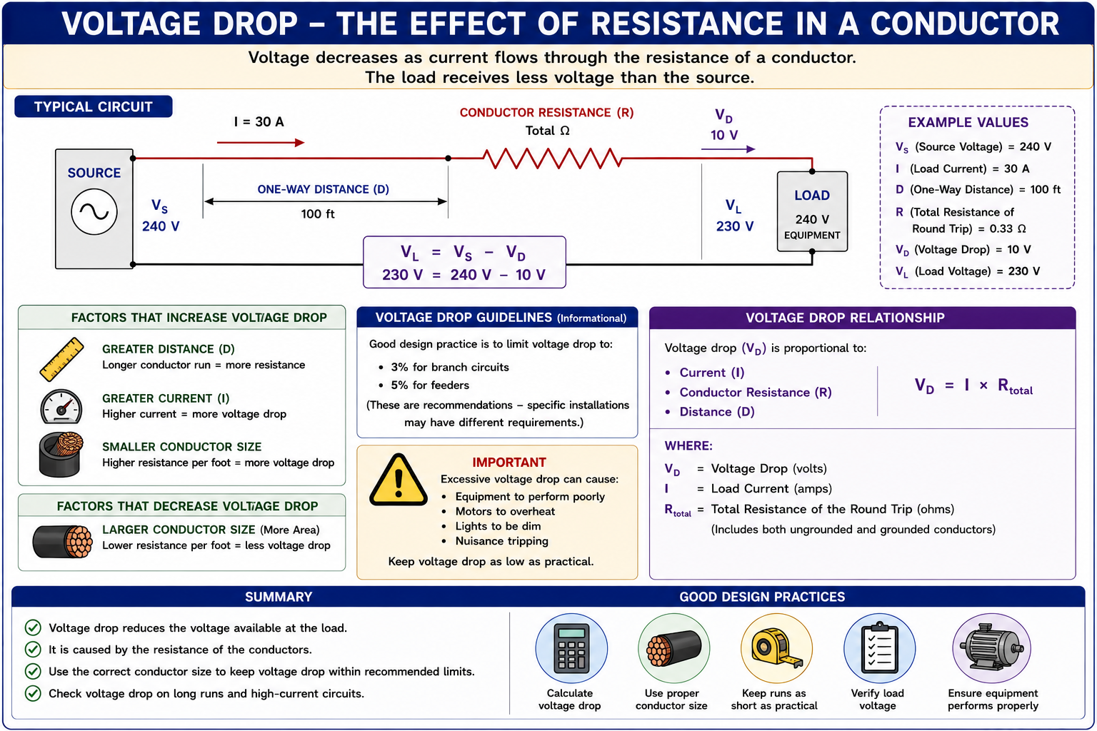
A conductor is not an ideal zero-resistance connection. When current flows through conductor resistance, part of the source voltage appears across the conductor itself. The remaining voltage is available at the load.
Voltage drop becomes increasingly important as circuit length and load current increase. Conductor material and conductor cross-sectional area also affect resistance and therefore affect the voltage available at the utilization equipment.
Voltage Drop Is an Application of Ohm’s Law
The basic reason voltage drops along a conductor is the same relationship introduced earlier in Ohm’s Law. A conductor has resistance, and current flowing through that resistance produces a voltage difference.
Voltage Drop Across Resistance
VD = I × R
Where VD is voltage drop in volts, I is circuit current in amperes, and R is the applicable conductor resistance in ohms.
If a circuit carries 30 A through conductors having a total circuit resistance of 0.33 ohm, the approximate conductor voltage drop is:
VD = 30 × 0.33 = 9.9 V
Subtract Conductor Drop From Source Voltage
Once conductor voltage drop has been determined, the approximate voltage available at the load can be found by subtracting the conductor drop from the source voltage.
Load Voltage
VL = VS − VD
Where VL is load voltage, VS is source voltage, and VD is conductor voltage drop.
If a 240 V circuit has approximately 10 V of conductor voltage drop, the load receives approximately:
240 V − 10 V = 230 V
Current, Length, Material, and Conductor Size Matter
Voltage drop is determined by conductor resistance and the amount of current flowing through the circuit. Several physical and electrical factors therefore influence the final result.
Current
Increasing current increases voltage drop when conductor resistance remains unchanged.
Length
Increasing conductor length increases resistance and therefore increases voltage drop.
Conductor Size
Increasing conductor cross-sectional area reduces resistance and therefore reduces voltage drop.
Conductor Material
Copper and aluminum have different resistivity values, so conductor material affects resistance and voltage drop.
Temperature
Conductor resistance changes with temperature, so actual operating conditions can affect voltage drop.
Circuit Configuration
Single-phase and three-phase circuits use different voltage-drop relationships because of their circuit geometry and phase relationships.
K Represents Conductor Resistivity in the Approximation
A commonly used voltage-drop calculation method uses a K-factor representing conductor resistivity. Using resistance values based on NEC Chapter 9, Table 8 at 75°C, approximate K values commonly used for calculations are 12.9 for uncoated copper and 21.2 for aluminum.
Copper
A commonly used approximate K value for uncoated copper at 75°C is 12.9.
Aluminum
A commonly used approximate K value for aluminum at 75°C is 21.2.
Calculation point: K-factor formulas are useful approximations. When a problem provides a specific conductor resistance, temperature, material property, table value, or required calculation method, use the information supplied by the problem or applicable reference.
Account for the Complete Circuit Path
For a common single-phase two-wire voltage-drop calculation using one-way circuit length, the conductor path extends from the source to the load and back to the source. The factor of 2 in the formula accounts for this complete circuit path.
Approximate K-Factor Formula
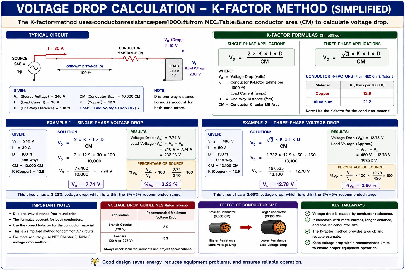
VD = (2 × K × I × D) / CM
Where VD is voltage drop in volts, K is the conductor K-factor, I is current in amperes, D is the one-way distance to the load in feet, and CM is conductor area in circular mils.
Common error: When the formula already contains the factor of 2, use the one-way distance to the load. Do not double the distance again.
Calculate Voltage Drop in a Copper Circuit
A 240 V single-phase circuit supplies a 30 A load located 100 feet from the source. Assume an uncoated copper conductor with a K-factor of 12.9 and a conductor area of 10,000 circular mils. Determine the approximate voltage drop and percentage voltage drop.
List the Known Values
K = 12.9, I = 30 A, D = 100 ft, CM = 10,000, and source voltage = 240 V.
Select the Formula
VD = (2 × K × I × D) / CM.
Substitute
VD = (2 × 12.9 × 30 × 100) / 10,000.
Calculate Voltage Drop
VD = 7.74 V.
Calculate Percentage
Percent voltage drop = (7.74 / 240) × 100 = approximately 3.23%.
Answer: The approximate conductor voltage drop is 7.74 V, or about 3.23% of the 240 V source voltage.
Use √3 Instead of 2
For a balanced three-phase circuit using the same simplified K-factor method, the multiplier √3 replaces the factor of 2 used in the single-phase formula.
Approximate K-Factor Formula
VD = (√3 × K × I × D) / CM
For calculation purposes, √3 is approximately 1.732.
Exam point: Identify whether the circuit is single-phase or three-phase before selecting the voltage-drop formula. Using 2 instead of √3, or √3 instead of 2, changes the result.
Calculate Voltage Drop in a Three-Phase Circuit
A 480 V three-phase circuit supplies a 50 A load located 150 feet from the source. Assume uncoated copper conductors with K = 12.9 and a conductor area of 13,100 circular mils. Determine the approximate voltage drop and percentage voltage drop.
List the Known Values
K = 12.9, I = 50 A, D = 150 ft, CM = 13,100, and line-to-line source voltage = 480 V.
Select the Three-Phase Formula
VD = (1.732 × K × I × D) / CM.
Substitute
VD = (1.732 × 12.9 × 50 × 150) / 13,100.
Calculate Voltage Drop
VD = approximately 12.79 V.
Calculate Percentage
Percent voltage drop = (12.79 / 480) × 100 = approximately 2.66%.
Answer: The approximate voltage drop is 12.79 V, or about 2.66% of the 480 V line-to-line source voltage.
Convert Voltage Drop Into a Percentage of Circuit Voltage
Voltage drop is often easier to evaluate when expressed as a percentage of the nominal or specified circuit voltage.
Percentage Voltage Drop
Percent VD = (VD / Vsource) × 100
For example, a 6 V drop on a 240 V circuit is:
(6 / 240) × 100 = 2.5%
Understand the Difference Between Design Guidance and a Mandatory Rule
Voltage-drop provisions must be read in their actual Code context. The NEC includes informational guidance associated with feeders and branch circuits intended to promote reasonable efficiency of operation, while particular installations can have specific voltage-drop requirements elsewhere in the Code.
A commonly encountered design objective is approximately 3% maximum voltage drop on a branch circuit and approximately 5% total voltage drop for the combined feeder and branch circuit to the farthest outlet. These values should not be treated as a universal mandatory maximum applying identically to every electrical installation.
NASCLA reference-book point: When an exam question asks what the NEC requires or recommends, use the applicable language in the current approved reference rather than assuming that every circuit is governed by a universal 3% or 5% mandatory limit.
Rearrange the Formula to Find Circular-Mil Area
A voltage-drop problem may specify the maximum allowable voltage drop and ask for the minimum calculated conductor area rather than asking directly for volts dropped.
Required Circular Mils
CM = (2 × K × I × D) / VD
Required Circular Mils
CM = (√3 × K × I × D) / VD
Important: A calculated circular-mil requirement does not by itself establish the final conductor size. The selected conductor must also satisfy applicable ampacity, termination, temperature, installation, equipment, and Code requirements.
Determine the Required Circular-Mil Area
A 240 V single-phase circuit carries 40 A to a load 150 feet from the source. The design permits a maximum conductor voltage drop of 7.2 V. Assume uncoated copper with K = 12.9. Determine the minimum calculated conductor area based only on voltage drop.
Use the Rearranged Formula
CM = (2 × K × I × D) / VD.
Substitute
CM = (2 × 12.9 × 40 × 150) / 7.2.
Calculate
CM = 21,500 circular mils.
Select an Actual Conductor
Use the applicable conductor table to select a standard conductor having at least the required calculated circular-mil area, then separately verify all applicable ampacity and installation requirements.
The Formula Can Also Determine Circuit Distance
If conductor size, current, K-factor, and permitted voltage drop are known, the equation can be rearranged to determine the approximate maximum one-way circuit length.
Maximum One-Way Distance
D = (CM × VD) / (2 × K × I)
Maximum One-Way Distance
D = (CM × VD) / (√3 × K × I)
Material Changes the Calculated Voltage Drop
Because the commonly used K-factor for aluminum is higher than the corresponding value for uncoated copper, equal-length conductors having the same circular-mil area and carrying the same current will produce different approximate voltage drops.
Uncoated Copper
Using K ≈ 12.9 produces a lower calculated voltage drop than an equal-area aluminum conductor under otherwise identical conditions.
Aluminum
Using K ≈ 21.2 produces a greater calculated voltage drop when conductor area, current, and distance remain the same.
Exam point: Always check conductor material before inserting the K-factor. Using the copper value in an aluminum-conductor problem can significantly understate the calculated voltage drop.
K-Factor Is Not the Only Calculation Method
Voltage drop can also be calculated using conductor resistance or impedance values obtained from appropriate reference tables. If the total circuit resistance is known, Ohm’s Law can be applied directly using VD = I × R.
For AC circuits where reactance and power factor materially affect the result, an impedance-based calculation can provide greater accuracy than a simplified K-factor resistance calculation. Follow the method and reference information appropriate to the problem being solved.
Write Down the Variables Before Calculating
Voltage-drop questions often contain enough numbers to encourage formula mistakes. Before using the calculator, identify circuit phase, conductor material, current, one-way distance, conductor area, source voltage, and exactly what the question asks you to find.
Then select the formula. For the simplified K-factor method, use 2 for single-phase and √3 for three-phase. After calculating volts dropped, calculate percentage only if the question asks for it or if it helps verify the result.
Use the Same Process for Every Voltage-Drop Problem
Identify the Circuit
Determine whether the problem involves single-phase or three-phase power.
Identify Conductor Material
Determine whether the conductors are copper, aluminum, or another specified material.
Identify Current
Determine the current to use in the voltage-drop calculation.
Identify Distance
Determine the one-way distance to the load when using the standard formulas presented in this lesson.
Identify Conductor Area
Obtain the circular-mil area from the problem or appropriate conductor reference.
Select and Solve the Formula
Use the single-phase or three-phase relationship and solve for the requested quantity.
Check the Result
Confirm units, percentage, conductor selection, and whether the result is reasonable for the circuit described.
Avoid These Voltage-Drop Mistakes
Doubling Distance Twice
If the single-phase formula already includes the factor of 2, use one-way distance rather than doubling the distance separately.
Using 2 for Three-Phase
The simplified balanced three-phase formula uses √3 rather than the single-phase multiplier of 2.
Using the Wrong K-Factor
Confirm whether the conductor is copper or aluminum before selecting the resistivity value.
Confusing Volts With Percent
Voltage drop in volts and percentage voltage drop are different quantities. Calculate the percentage by dividing volts dropped by circuit voltage and multiplying by 100.
Ignoring Circular Mils
The K-factor formula uses conductor area in circular mils, not the AWG number itself.
Treating 3% and 5% as Universal Mandatory Limits
Read the applicable NEC provision and exam question carefully. General voltage-drop recommendations and specific mandatory requirements are not the same thing.
Check Your Understanding
Question 1
If circuit current increases while conductor resistance remains unchanged, what happens to voltage drop?
A. It decreases.
B. It increases.
C. It becomes zero.
D. It becomes independent of resistance.
Question 2
Which approximate K-factor is commonly used for uncoated copper conductors at 75°C in the simplified method presented in this lesson?
A. 1.732
B. 12.9
C. 21.2
D. 75
Question 3
Which multiplier is used in the simplified three-phase K-factor voltage-drop formula?
A. 1.0
B. 1.414
C. 1.732
D. 2.0
Question 4
A 240 V circuit has a voltage drop of 6 V. What is the percentage voltage drop?
A. 1.25%
B. 2.5%
C. 4.0%
D. 6.0%
Question 5
What generally happens to voltage drop when conductor cross-sectional area is increased while material, current, and length remain unchanged?
A. Voltage drop increases.
B. Voltage drop decreases.
C. Voltage drop doubles.
D. Voltage drop becomes equal to source voltage.
Question 6
Which statement about the commonly cited 3% and 5% voltage-drop values is most accurate?
A. They are universal mandatory maximums for every NEC circuit.
B. They are commonly encountered design recommendations, while specific applications can have separate requirements.
C. They apply only to DC circuits.
D. They replace manufacturer voltage requirements.
Practice Question Explanations
B — It Increases
VD = I × R. If resistance remains unchanged, increasing current increases voltage drop.
B — 12.9
Approximately 12.9 is commonly used for uncoated copper at 75°C in this simplified K-factor method.
C — 1.732
The simplified three-phase formula uses √3, approximately 1.732.
B — 2.5%
Percent voltage drop = (6 / 240) × 100 = 2.5%.
B — Voltage Drop Decreases
A larger conductor cross-sectional area reduces conductor resistance and therefore reduces voltage drop under otherwise equal conditions.
B — Common Design Recommendations
The familiar values are commonly used voltage-drop design guidance, but they should not be treated as a universal mandatory maximum for every installation. Always check the applicable Code provision and equipment requirements.
What You Should Take From This Lesson
Voltage Drop Comes From Conductor Resistance
Current flowing through conductor resistance produces a voltage difference according to VD = I × R.
Current and Length Increase Voltage Drop
Greater current and longer conductors increase voltage drop when other conditions remain unchanged.
Larger Conductors Reduce Voltage Drop
Increasing conductor cross-sectional area reduces resistance and therefore reduces voltage drop.
Material Matters
The simplified K-factor method commonly uses approximately 12.9 for uncoated copper and 21.2 for aluminum at 75°C.
Single-Phase Uses a Factor of 2
Using one-way distance, the simplified single-phase formula is VD = (2KID) / CM.
Three-Phase Uses √3
The corresponding simplified balanced three-phase formula is VD = (√3KID) / CM.
Know What the Percentage Means
Percentage voltage drop equals volts dropped divided by the applicable circuit voltage, multiplied by 100.
Read NEC Voltage-Drop Language Carefully
Distinguish general design recommendations from specific mandatory requirements that may apply to particular installations or equipment.
Leave a Reply
You must be logged in to post a comment.