Back to: NASCLA Master Electrical Contractor Exam Preparation
Electric motors convert electrical energy into mechanical energy and represent a major category of electrical load in commercial and industrial installations. Electrical contractors preparing for the NASCLA exam should understand the basic operating principles of AC motors, especially three-phase induction motors.
This lesson focuses on the rotating magnetic field, electromagnetic induction, synchronous speed, rotor speed, slip, motor direction, and the relationships between frequency, poles, and operating speed. These principles provide the foundation for recognizing motor behavior and solving basic motor calculations.
Three-Phase Current Creates a Rotating Magnetic Field
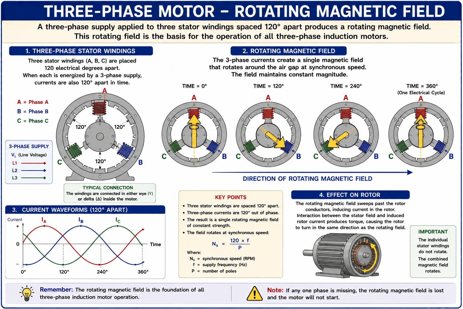
The operating principle of a three-phase induction motor begins with the stator. Three-phase current flowing through stator windings produces a magnetic field that rotates around the stator at a predictable synchronous speed.
The rotating stator field induces current in the rotor. Interaction between the rotor magnetic field and the rotating stator field produces torque, causing the rotor to turn in the same general direction as the rotating magnetic field.
The Stator Produces the Field and the Rotor Produces Mechanical Motion
An induction motor has a stationary portion called the stator and a rotating portion called the rotor. The stator contains windings connected to the AC supply. The rotor is positioned inside the stator and is mechanically connected to the motor shaft.
Stator
The stationary portion of the motor contains the windings that establish the rotating magnetic field.
Rotor
The rotating portion develops torque through electromagnetic interaction with the stator field and transfers that torque to the motor shaft.
Air Gap
A small physical gap separates the stator from the rotor while allowing magnetic flux to couple the two portions of the motor.
Shaft
The shaft transfers the motor’s mechanical torque and rotation to the connected equipment.
Three Phase Currents Do Not Reach Their Peaks at the Same Time
The three currents in a balanced three-phase system are displaced from one another by 120 electrical degrees. When these currents flow through appropriately arranged stator windings, their individual magnetic fields combine to form a resultant magnetic field that rotates around the stator.
The rotational speed of this magnetic field is called synchronous speed. It depends on supply frequency and the number of motor poles.
Connection to Lesson 13: The same 120-degree phase displacement that determines three-phase voltage relationships also allows a three-phase motor stator to produce a rotating magnetic field.
Frequency and Number of Poles Determine Field Speed
Synchronous speed is the rotational speed of the magnetic field produced by the stator. Increasing supply frequency increases synchronous speed, while increasing the number of motor poles decreases synchronous speed.
Synchronous Speed
NS = (120 × f) / P
Where NS is synchronous speed in revolutions per minute, f is supply frequency in hertz, and P is the number of motor poles.
2 Poles at 60 Hz
NS = (120 × 60) / 2 = 3,600 RPM.
4 Poles at 60 Hz
NS = (120 × 60) / 4 = 1,800 RPM.
6 Poles at 60 Hz
NS = (120 × 60) / 6 = 1,200 RPM.
8 Poles at 60 Hz
NS = (120 × 60) / 8 = 900 RPM.
Determine the Synchronous Speed of a Motor
A three-phase induction motor has six poles and operates from a 60 Hz supply. Determine the synchronous speed of the rotating magnetic field.
Identify the Known Values
Frequency = 60 Hz and number of poles = 6.
Select the Formula
NS = (120 × f) / P.
Substitute
NS = (120 × 60) / 6.
Calculate
NS = 1,200 RPM.
Answer: The stator magnetic field rotates at a synchronous speed of 1,200 RPM.
The Rotor Does Not Need a Direct Electrical Connection to the Supply
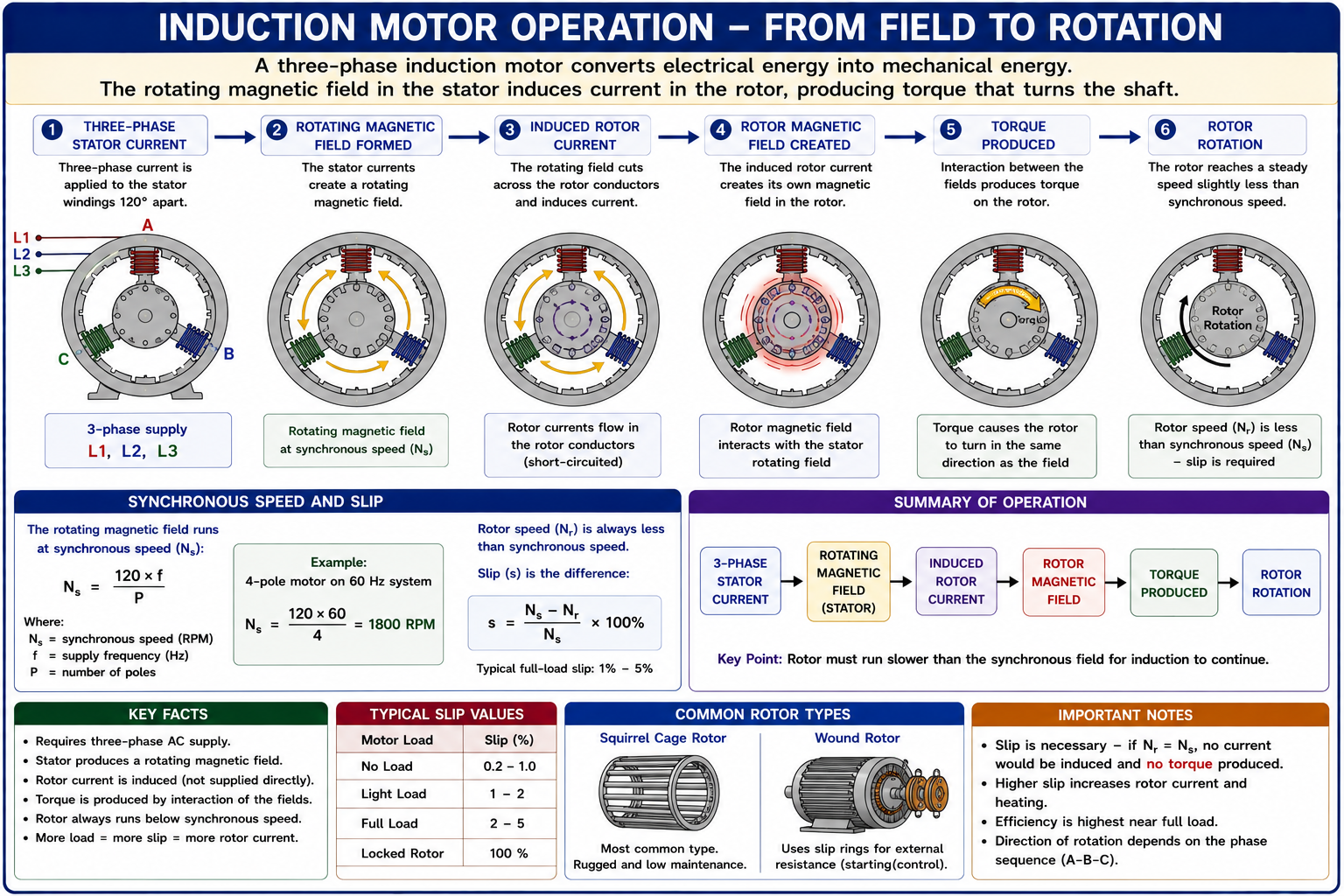
In a common squirrel-cage induction motor, the rotor conductors are not directly connected to the external AC supply. Instead, relative motion between the rotating stator field and the rotor conductors produces changing magnetic flux and induces rotor current.
The induced rotor current produces its own magnetic field. Interaction between the rotor field and the rotating stator field develops electromagnetic torque and causes the rotor to accelerate.
Follow the Energy Conversion Process
Three-Phase Current Enters the Stator
Three-phase AC current flows through the stator windings.
A Rotating Magnetic Field Is Established
The phase-displaced stator currents combine to produce a magnetic field rotating at synchronous speed.
Rotor Current Is Induced
Relative motion between the rotating field and rotor conductors induces current in the rotor.
The Rotor Develops a Magnetic Field
The induced rotor current establishes magnetic effects within the rotor.
Electromagnetic Torque Develops
Interaction between the stator and rotor magnetic fields produces torque.
The Rotor Turns
The rotor accelerates in the direction of the rotating magnetic field and delivers mechanical output through the shaft.
An Induction Motor Rotor Operates Below Synchronous Speed
The rotor of a normal induction motor must rotate at a speed slightly different from the rotating stator field for induction to continue producing rotor current and torque. Under ordinary motoring operation, rotor speed is therefore below synchronous speed.
The difference between synchronous speed and actual rotor speed is called slip. Slip can be stated as a speed difference in RPM or as a percentage of synchronous speed.
Percent Slip
Slip (%) = [(NS − NR) / NS] × 100
Where NS is synchronous speed and NR is actual rotor speed.
Calculate Motor Slip
A four-pole induction motor operates from a 60 Hz source and turns at 1,750 RPM under load. Determine its percent slip.
Calculate Synchronous Speed
NS = (120 × 60) / 4 = 1,800 RPM.
Find the Speed Difference
NS − NR = 1,800 − 1,750 = 50 RPM.
Calculate Percent Slip
Slip = (50 / 1,800) × 100 = approximately 2.78%.
Answer: The motor operates with approximately 2.8% slip at 1,750 RPM.
Synchronous Speed Is Not the Same as Induction-Motor Rotor Speed
A four-pole 60 Hz induction motor has a synchronous speed of 1,800 RPM, but its nameplate full-load speed may be somewhat lower, such as 1,750 RPM or another value determined by the motor design and operating load.
If a basic motor question asks for synchronous speed, use frequency and number of poles. If it asks for slip, compare actual rotor speed with synchronous speed.
Rotor Speed Changes as Motor Load Changes
As mechanical load is applied to an induction motor, the rotor normally slows slightly relative to the rotating stator field. The increased relative motion increases induction in the rotor and allows the motor to develop additional torque.
Within normal operating limits, induction-motor slip therefore changes with load. The exact relationship depends on motor design and operating conditions.
Field point: Do not assume that a motor’s actual running speed should exactly equal its calculated synchronous speed. A normal induction motor requires slip to produce torque.
Phase Sequence Determines the Direction of the Rotating Field
The order in which the three phases reach the motor windings determines the direction of the stator’s rotating magnetic field. Changing the phase sequence changes the direction of rotation.
For a conventional three-phase motor, interchanging any two phase conductors reverses the phase sequence and normally reverses motor rotation.
Original Phase Sequence
A particular A-B-C phase sequence produces rotation in one direction.
Two Phases Interchanged
Interchanging any two phase conductors reverses the phase sequence and the rotating magnetic field.
Result
The motor normally rotates in the opposite direction after the phase sequence is reversed.
Safety point: Motor rotation should be verified according to equipment and manufacturer procedures before the driven equipment is placed into normal service. Unexpected reverse rotation can damage pumps, compressors, fans, conveyors, and other machinery.
Induction Motors Can Use Different Rotor Constructions
The squirrel-cage rotor is widely used because of its simple and rugged construction. Wound-rotor induction motors use rotor windings connected through slip rings and may be used where particular starting or speed-control characteristics are required.
Squirrel-Cage Rotor
Conductive rotor bars are connected at their ends to form a closed conductive structure in which rotor current is induced.
Wound Rotor
The rotor contains windings with external connections through slip rings, allowing additional control of rotor-circuit characteristics in applicable motor designs.
Nameplate RPM Provides a Clue to Pole Count
Because induction motors operate below synchronous speed, common nameplate speeds can often suggest the motor’s approximate synchronous speed and number of poles.
Near 3,600 RPM
A 60 Hz induction motor with a full-load speed somewhat below 3,600 RPM is generally associated with a two-pole design.
Near 1,800 RPM
A full-load speed somewhat below 1,800 RPM generally indicates a four-pole 60 Hz motor.
Near 1,200 RPM
A full-load speed somewhat below 1,200 RPM generally indicates a six-pole 60 Hz motor.
Near 900 RPM
A full-load speed somewhat below 900 RPM generally indicates an eight-pole 60 Hz motor.
Rearrange the Synchronous-Speed Formula
If frequency and synchronous speed are known, the synchronous-speed formula can be rearranged to determine the number of motor poles.
Determine Number of Poles
P = (120 × f) / NS
For example, a motor with a synchronous speed of 1,800 RPM operating at 60 Hz has:
P = (120 × 60) / 1,800 = 4 poles
Changing Frequency Changes Synchronous Speed
Because frequency appears directly in the synchronous-speed equation, changing the frequency supplied to an AC motor changes the speed of the rotating magnetic field. This relationship is fundamental to variable-frequency motor control.
4 Poles at 60 Hz
NS = (120 × 60) / 4 = 1,800 RPM.
4 Poles at 50 Hz
NS = (120 × 50) / 4 = 1,500 RPM.
4 Poles at 30 Hz
NS = (120 × 30) / 4 = 900 RPM.
Calculation point: If the number of poles remains unchanged, synchronous speed changes directly with supply frequency.
Separate Synchronous Speed From Actual Speed
When a motor question provides frequency and pole count, determine whether it is asking for synchronous speed or actual rotor speed. Frequency and pole count alone determine synchronous speed; they do not determine the exact loaded rotor speed of an induction motor.
If actual rotor RPM is also supplied, the question may be asking for slip. Calculate synchronous speed first, then compare it with rotor speed.
Avoid These Motor-Theory Mistakes
Using Rotor Speed as Synchronous Speed
Induction-motor rotor speed is normally below synchronous speed during motoring operation.
Forgetting the Number of Poles
Synchronous speed depends on both supply frequency and motor pole count.
Using Pole Pairs Instead of Poles
In NS = 120f/P, P represents the total number of poles, not the number of pole pairs.
Reversing the Slip Formula
For normal motoring operation, subtract rotor speed from synchronous speed before dividing by synchronous speed.
Assuming Zero Slip Is Normal
A conventional induction motor requires relative motion between the stator field and rotor to induce rotor current and develop torque.
Changing All Three Phases to Reverse Rotation
Reversing conventional three-phase motor rotation is normally accomplished by interchanging any two phase conductors.
Check Your Understanding
Question 1
What is the synchronous speed of a four-pole motor operating at 60 Hz?
A. 900 RPM
B. 1,200 RPM
C. 1,800 RPM
D. 3,600 RPM
Question 2
What is the synchronous speed of a six-pole motor operating at 60 Hz?
A. 600 RPM
B. 900 RPM
C. 1,200 RPM
D. 1,800 RPM
Question 3
A four-pole, 60 Hz induction motor operates at 1,755 RPM. Approximately what is its percent slip?
A. 1.0%
B. 2.5%
C. 4.0%
D. 7.5%
Question 4
Which statement best describes the rotor speed of a normal induction motor operating as a motor?
A. It is always greater than synchronous speed.
B. It is normally slightly below synchronous speed.
C. It is always exactly equal to synchronous speed.
D. It is unrelated to synchronous speed.
Question 5
How can the direction of a conventional three-phase motor normally be reversed?
A. Increase the voltage.
B. Decrease the frequency.
C. Interchange any two phase conductors.
D. Disconnect the equipment grounding conductor.
Question 6
A 60 Hz induction motor has a synchronous speed of 900 RPM. How many poles does the motor have?
A. 2
B. 4
C. 6
D. 8
Practice Question Explanations
C — 1,800 RPM
NS = (120 × 60) / 4 = 1,800 RPM.
C — 1,200 RPM
NS = (120 × 60) / 6 = 1,200 RPM.
B — 2.5%
Synchronous speed is 1,800 RPM. Slip = [(1,800 − 1,755) / 1,800] × 100 = 2.5%.
B — Slightly Below Synchronous Speed
A normal induction motor operating as a motor requires slip, so its rotor speed is somewhat below the synchronous speed of the stator field.
C — Interchange Any Two Phase Conductors
Interchanging any two phases reverses phase sequence and reverses the direction of the rotating magnetic field.
D — 8 Poles
P = (120 × 60) / 900 = 8 poles.
What You Should Take From This Lesson
Three-Phase Current Produces a Rotating Field
Phase-displaced currents in the stator windings establish a magnetic field that rotates around the stator.
The Rotor Develops Torque Through Induction
Relative motion between the rotating stator field and rotor induces rotor current, allowing electromagnetic torque to develop.
Frequency and Poles Determine Synchronous Speed
Use NS = 120f/P to calculate the speed of the rotating magnetic field.
More Poles Mean Lower Speed
At the same frequency, increasing the number of motor poles decreases synchronous speed.
Induction Motors Require Slip
During normal motoring operation, rotor speed is below synchronous speed so relative motion remains between the rotor and rotating stator field.
Slip Can Be Calculated
Percent slip compares the difference between synchronous speed and rotor speed with synchronous speed.
Phase Sequence Controls Rotation
Interchanging any two phase conductors normally reverses the direction of a conventional three-phase motor.
Leave a Reply
You must be logged in to post a comment.