Back to: NASCLA Master Electrical Contractor Exam Preparation
Transformers are used throughout electrical distribution systems to transfer AC electrical energy between circuits and change voltage and current levels. Electrical contractors must understand primary and secondary windings, step-up and step-down operation, turns ratios, current relationships, transformer power, and common transformer configurations.
This lesson develops the transformer relationships needed for NASCLA calculation questions. The emphasis is identifying the known values, determining the transformer ratio, applying that ratio in the correct direction, and checking whether the calculated voltage and current make sense for step-up or step-down operation.
Voltage Follows the Turns Ratio — Current Changes in the Opposite Direction
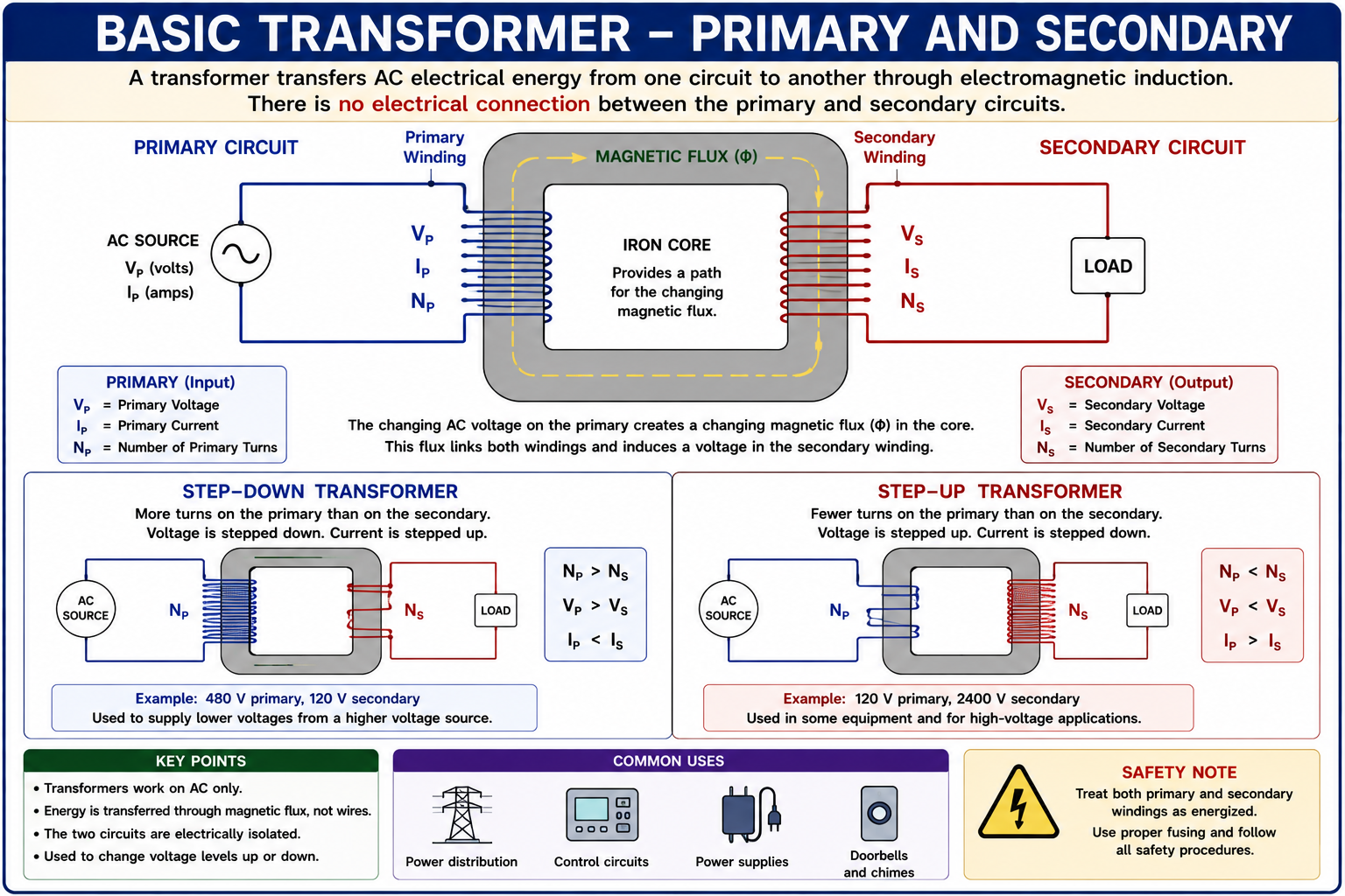
A basic transformer contains a primary winding and a secondary winding linked by magnetic flux in a common core. Applying alternating voltage to the primary produces changing magnetic flux, which induces voltage in the secondary winding.
The ratio between the number of primary and secondary turns determines the voltage relationship. In an ideal transformer, increasing voltage decreases current proportionally, while decreasing voltage increases current proportionally.
A Transformer Transfers Energy Through a Changing Magnetic Field
When alternating voltage is applied to the primary winding, alternating current establishes changing magnetic flux in the transformer core. That changing magnetic flux links the secondary winding and induces an alternating voltage across it.
In a conventional two-winding transformer, the primary and secondary windings are electrically separate while being magnetically coupled through the core. Energy is transferred through the magnetic field rather than by a direct conductive connection between the windings.
Primary Winding
The primary winding is the winding connected to the electrical source supplying the transformer.
Secondary Winding
The secondary winding is the winding from which transformed voltage is supplied to the connected load.
Magnetic Core
The core provides a magnetic path that couples the changing magnetic flux produced by the primary winding to the secondary winding.
Alternating Current
Normal transformer action requires changing magnetic flux, which is produced by an alternating or otherwise changing current rather than steady-state DC.
The Number of Secondary Turns Determines Whether Voltage Rises or Falls
If the secondary winding has more turns than the primary winding, the secondary voltage is greater than the primary voltage and the transformer operates as a step-up transformer. If the secondary has fewer turns, the secondary voltage is lower and the transformer operates as a step-down transformer.
Step-Up Transformer
NS > NP and VS > VP. Voltage increases while available current decreases in the corresponding ideal relationship.
Step-Down Transformer
NS < NP and VS < VP. Voltage decreases while available current increases in the corresponding ideal relationship.
1:1 Transformer
If the primary and secondary have equal turns, the ideal secondary voltage equals the primary voltage. This arrangement can be used where electrical isolation rather than a voltage change is the primary purpose.
Exam point: Before calculating, decide whether the transformer is stepping voltage up or down. That provides a quick reasonableness check for the final answer.
Voltage Ratio Equals Turns Ratio
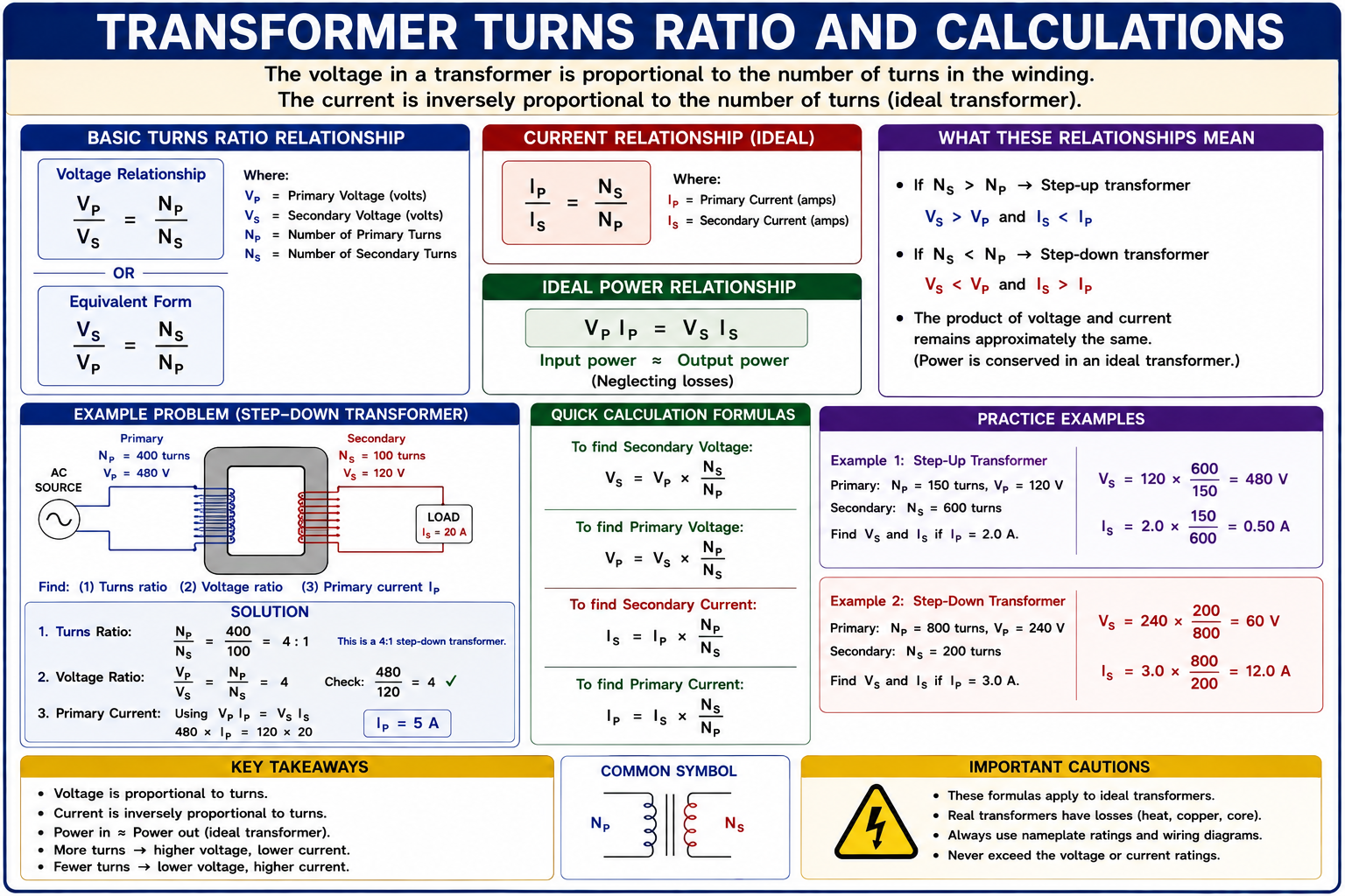
For an ideal transformer, the ratio of primary voltage to secondary voltage equals the ratio of primary winding turns to secondary winding turns.
Voltage and Turns Relationship
VP / VS = NP / NS
Equivalent form:
VS / VP = NS / NP
Where VP is primary voltage, VS is secondary voltage, NP is primary turns, and NS is secondary turns.
Calculate Secondary Voltage From the Turns Ratio
A transformer has 400 turns on the primary and 100 turns on the secondary. The primary is connected to 480 V. Determine the ideal secondary voltage.
Identify the Known Values
VP = 480 V, NP = 400 turns, and NS = 100 turns.
Write the Relationship
VS / VP = NS / NP.
Substitute the Values
VS / 480 = 100 / 400.
Solve
VS = 480 × 100 / 400 = 120 V.
Answer: The ideal secondary voltage is 120 V. The transformer is a 4:1 step-down transformer because the primary has four times as many turns as the secondary.
Transformer Current Changes Inversely With Voltage
For an ideal transformer, input power equals output power. Therefore, when voltage is stepped down, available current is stepped up proportionally. When voltage is stepped up, available current is stepped down proportionally.
Current and Turns Relationship
IP / IS = NS / NP
Equivalent form:
IS / IP = NP / NS
The current ratio is inverse to the voltage and turns ratio.
Memory point: Voltage follows the turns ratio. Current follows the inverse of the turns ratio.
Calculate Primary Current From Secondary Current
The 480 V to 120 V transformer in the previous example supplies 20 A from its secondary. Determine the ideal primary current.
Identify the Ratio
The voltage and turns ratio is 480:120, or 4:1.
Apply the Inverse Current Ratio
Because voltage was stepped down by a factor of four, current is stepped up by a factor of four.
Calculate Primary Current
IP = IS × VS / VP = 20 × 120 / 480 = 5 A.
Answer: The ideal primary current is 5 A when the secondary supplies 20 A.
Input Power Equals Output Power in the Ideal Model
An ideal transformer has no losses, so the electrical power entering the primary equals the power delivered by the secondary. Real transformers have winding, core, and other losses, but ideal-transformer relationships are useful for basic theory and calculation problems.
Primary Power Equals Secondary Power
VP × IP = VS × IS
Primary
480 V × 5 A = 2,400 VA.
Secondary
120 V × 20 A = 2,400 VA.
Reasonableness check: In the ideal example, both sides equal 2,400 VA. If your voltage and current calculations produce greatly different ideal primary and secondary power, recheck the ratios.
The Same Ratio Can Solve for Winding Turns
Transformer problems may provide primary and secondary voltages and the number of turns in one winding, then ask for the number of turns in the other winding.
Given
A transformer has a 240 V primary with 600 turns and a 24 V secondary. Determine the required secondary turns.
Write the Formula
VP / VS = NP / NS.
Substitute
240 / 24 = 600 / NS.
Solve
The voltage ratio is 10:1, so NS = 600 / 10 = 60 turns.
Answer: The secondary requires 60 turns in the ideal transformer model.
Transformers Are Commonly Rated in Volt-Amperes
Transformer capacity is commonly expressed in volt-amperes or kilovolt-amperes because the windings and conductors must carry current regardless of the load power factor. The nameplate kVA rating therefore provides an important basis for transformer current calculations.
Calculate Current From Transformer VA
I = VA / V
For values expressed in kVA:
I = (kVA × 1000) / V
Determine Full-Load Current of a Single-Phase Transformer
A 25 kVA single-phase transformer has a 240 V secondary. Determine the secondary current represented by the transformer rating.
Convert kVA to VA
25 kVA × 1000 = 25,000 VA.
Apply the Formula
I = VA / V = 25,000 / 240.
Calculate
I = approximately 104.2 A.
Answer: A 25 kVA single-phase transformer rated 240 V on the secondary corresponds to approximately 104.2 A at rated secondary output.
Three-Phase kVA Calculations Include √3
For a balanced three-phase transformer, line current can be calculated from the transformer kVA rating and line-to-line voltage using the same three-phase apparent-power relationship introduced in Lesson 13.
Balanced Three-Phase Transformer Formula
I = VA / (√3 × VLL)
For a transformer rated in kVA:
I = (kVA × 1000) / (√3 × VLL)
A 75 kVA three-phase transformer with a 208 V line-to-line secondary has a rated secondary line current of approximately 208 A because 75,000 / (1.732 × 208) is approximately 208 A.
A Transformer Does Not Have to Change Voltage
An isolation transformer can have approximately equal primary and secondary voltages while maintaining electrical separation between the two windings. A 1:1 transformer therefore demonstrates that voltage transformation and electrical isolation are separate transformer functions.
Exam point: Do not assume every transformer must step voltage up or down. Equal primary and secondary turns can produce approximately equal voltages while still providing magnetic coupling between electrically separate windings.
An Autotransformer Uses a Common Winding
An autotransformer differs from a conventional two-winding transformer because portions of a single winding are common to both the input and output circuits. As a result, an autotransformer does not provide the same electrical isolation between primary and secondary circuits as a conventional isolated two-winding transformer.
Autotransformer arrangements can be used to raise or lower voltage and are also the basis for many buck-boost applications.
Two-Winding Transformer
Primary and secondary windings are electrically separate and magnetically coupled.
Autotransformer
Input and output share part of the same winding, so there is a conductive connection between portions of the circuits.
Small Voltage Corrections Can Be Made by Adding or Subtracting Transformer Voltage
Buck-boost transformer arrangements are commonly used when the available supply voltage needs a relatively small increase or decrease. Depending on the connection, transformer winding voltage can be added to the source voltage to boost it or subtracted from the source voltage to buck it.
Actual buck-boost installations depend on transformer ratings, winding configuration, manufacturer connection diagrams, grounding and bonding requirements, overcurrent protection, and applicable electrical-code requirements. Do not determine field connections from a simplified turns-ratio calculation alone.
Keep the Ratios in the Same Order
A common transformer-calculation error is reversing one ratio while leaving another unchanged. If you write primary voltage over secondary voltage, write primary turns over secondary turns in the same order.
Then use transformer behavior as a reasonableness check. More secondary turns should produce higher secondary voltage. Less secondary voltage should correspond to greater secondary current in the ideal model.
Avoid These Transformer Calculation Mistakes
Reversing the Turns Ratio
Keep primary and secondary quantities in corresponding positions throughout the equation.
Changing Current in the Wrong Direction
For an ideal transformer, voltage and current change in opposite directions. Stepping voltage down increases available current.
Treating kVA as kW
Transformer ratings are commonly expressed in apparent power. Do not automatically treat a kVA rating as an equal kW load.
Forgetting √3
Balanced three-phase transformer line-current calculations require √3 when line-to-line voltage is used.
Assuming an Autotransformer Provides Isolation
An autotransformer has a conductive winding connection between input and output and does not provide the isolation of separate primary and secondary windings.
Ignoring Reasonableness
A step-down transformer should not produce a calculated secondary voltage greater than its primary voltage unless the ratio or transformer description has been misunderstood.
Check Your Understanding
Question 1
A transformer has 500 primary turns and 100 secondary turns. If the primary voltage is 600 V, what is the ideal secondary voltage?
A. 100 V
B. 120 V
C. 300 V
D. 3,000 V
Question 2
A transformer changes 240 V to 480 V. Which statement is correct for the ideal transformer?
A. The transformer steps voltage down and current up.
B. The transformer steps voltage up and current down.
C. Voltage and current both double.
D. Voltage doubles while current remains unchanged.
Question 3
A 480 V to 120 V ideal transformer supplies 40 A on its secondary. Approximately what current is drawn by its primary?
A. 5 A
B. 10 A
C. 40 A
D. 160 A
Question 4
A 30 kVA single-phase transformer has a 240 V secondary. Approximately what is its rated secondary current?
A. 72 A
B. 125 A
C. 173 A
D. 240 A
Question 5
A 45 kVA three-phase transformer has a 208 V secondary. Approximately what is its rated secondary line current?
A. 72 A
B. 108 A
C. 125 A
D. 216 A
Question 6
Which transformer type normally has a portion of its winding common to both the input and output circuits?
A. Isolation transformer
B. Autotransformer
C. Conventional two-winding transformer
D. Current-limiting reactor
Practice Question Explanations
B — 120 V
VS / VP = NS / NP. Therefore VS = 600 × 100 / 500 = 120 V.
B — Voltage Up, Current Down
Increasing voltage from 240 V to 480 V makes this a step-up transformer. In the ideal relationship, current decreases by the inverse ratio.
B — 10 A
The voltage ratio is 480:120, or 4:1. The secondary current is four times the primary current, so 40 A / 4 = 10 A.
B — 125 A
I = VA / V = 30,000 / 240 = 125 A.
C — Approximately 125 A
I = 45,000 / (1.732 × 208) = approximately 124.9 A, or about 125 A.
B — Autotransformer
An autotransformer uses a common winding arrangement rather than electrically separate primary and secondary windings.
What You Should Take From This Lesson
Transformers Require Changing Magnetic Flux
Alternating voltage applied to the primary creates changing magnetic flux that induces voltage in the secondary winding.
Voltage Follows Turns
The ideal voltage relationship is VP / VS = NP / NS.
Current Changes Inversely
When ideal transformer voltage increases, available current decreases proportionally, and vice versa.
Ideal Power Is Conserved
For an ideal transformer, VPIP = VSIS.
Transformer Capacity Is Commonly Expressed in VA or kVA
Single-phase and three-phase current can be calculated from transformer apparent-power rating and system voltage.
Isolation and Voltage Transformation Are Different Functions
A conventional two-winding transformer can provide electrical separation even when its primary and secondary voltages are equal.
Autotransformers Share a Winding
Autotransformers use a winding common to input and output and therefore do not provide the electrical separation of a conventional two-winding transformer.
Leave a Reply
You must be logged in to post a comment.