Testing the DC Side of String-Inverter Systems
Once the AC side has been verified, troubleshooting a string-inverter PV system can move to the DC input side. The technician’s objective is to determine whether the array is supplying the inverter with reasonable DC voltage and current and, when an abnormal condition is found, narrow the problem to the affected string or circuit.
DC troubleshooting should progress from broad system measurements toward individual circuits. Begin at the inverter, compare the available DC inputs, and move toward individual strings only when the measurements indicate that additional isolation is necessary.
Determine Whether DC Power Is Reaching the Inverter
A string inverter depends on the PV array for its DC input. If acceptable AC grid conditions are present but the inverter is producing little or no power, the next question is whether the expected DC voltage and current are reaching the inverter.
Testing at the inverter evaluates a large portion of the DC system with relatively few measurements. If an input is abnormal, the technician can then move toward the combiner, string wiring, connectors, and ultimately the modules themselves.
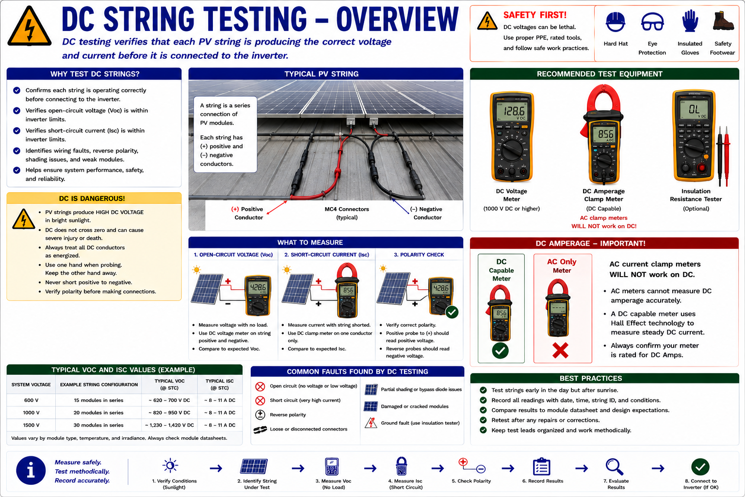
Understand What the Inverter Should Receive
In a conventional string-inverter system, PV modules are connected in series to form strings. The voltage of the individual modules adds together, while string current is determined primarily by the operating current of the series circuit.
One or more strings may connect directly to separate inverter inputs, or several strings may first be combined in a combiner box before reaching the inverter. The installed architecture determines which individual circuits can be measured and compared.
Technician focus: Know the module count, string configuration, inverter input arrangement, and expected voltage range before interpreting any DC measurement.
Work From the Inverter Toward the Array
Review Inverter Information
Check operating status, DC input information, fault codes, monitoring data, and the inverter’s allowable DC operating range.
Measure DC Voltage at the Inverter
Determine whether the array is supplying reasonable DC voltage to the inverter input.
Compare Available Inputs
Where multiple inputs or MPPT channels are available, compare similar circuits under the same conditions.
Move to Individual Strings
If the broader measurement identifies an abnormal input, isolate the investigation to the associated string circuits.
Locate the Abnormal Circuit
Use voltage, current, visual findings, and circuit comparisons to determine where expected electrical operation changes.
Move to Module Level Only When Necessary
Individual module and optimizer testing comes after the broader DC circuit has localized the problem.
Is Array Voltage Reaching the DC Input?
The inverter DC input is one of the most useful first test locations on a string-inverter system. A single measurement can establish whether the upstream PV circuit is providing voltage to the inverter.
Use a properly rated meter configured for DC voltage. Verify the expected polarity and voltage range before contacting the test points.
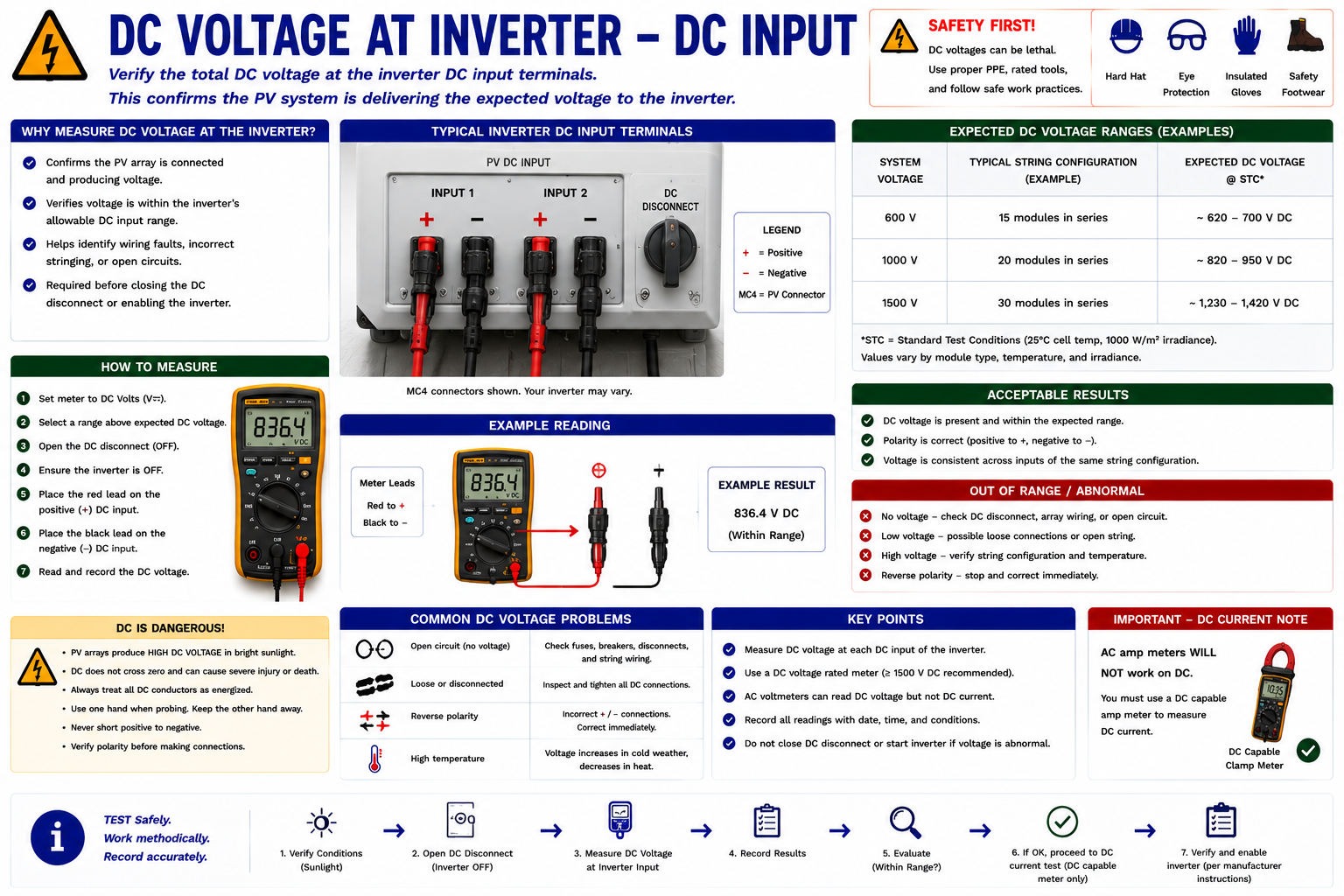
PV DC Voltage Can Remain Present With the AC Side Off
Opening the AC breaker or AC disconnect does not stop illuminated PV modules from producing DC voltage. Likewise, operating a DC disconnect may leave the array side of that disconnect energized.
Always identify which side of the circuit remains connected to the PV source and treat PV source conductors as potentially energized whenever sufficient light reaches the modules.
Estimate What Should Be Present Before Measuring
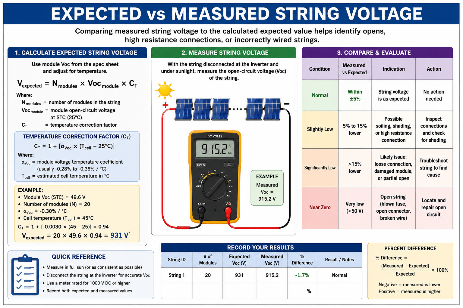
Series-connected module voltages add together. This allows the technician to estimate a reasonable string voltage from the module specifications and the number of modules connected in series.
Approximate string open-circuit voltage = Module Voc × Number of series-connected modules
For example, if a module has an open-circuit voltage of approximately 40 volts and 10 identical modules are connected in series, the string would have a nominal open-circuit voltage near 400 volts under the module’s specified test conditions.
Actual field voltage varies with module temperature, irradiance, equipment configuration, operating state, and other conditions. The calculation establishes an expectation, not an exact field requirement.
PV Voltage Changes With Module Temperature
Module voltage is temperature dependent. As cell temperature rises, PV voltage generally decreases. Under cold conditions, open-circuit voltage can rise above the value expected at warmer operating temperatures.
For precise calculations, use the module manufacturer’s temperature coefficients and the applicable design or service procedure. For troubleshooting, temperature should at least be considered when deciding whether a measured voltage is reasonable.
Similar Circuits Provide a Powerful Reference
Many string inverters have multiple DC inputs or maximum power point tracking channels. When the connected strings have similar module counts, orientation, equipment, and sunlight exposure, their electrical measurements should generally be comparable.
A significant difference between otherwise similar inputs can quickly identify which portion of the array requires further investigation.
Move Upstream After the Problem Has Been Narrowed
If an inverter input is abnormal, determine which individual string or upstream circuit contributes to that input. Depending on the installation, this may be possible at a combiner box, inverter string terminals, fused inputs, or other accessible equipment.
Measure comparable strings under similar environmental conditions. Record both the measurement and the circuit identification.
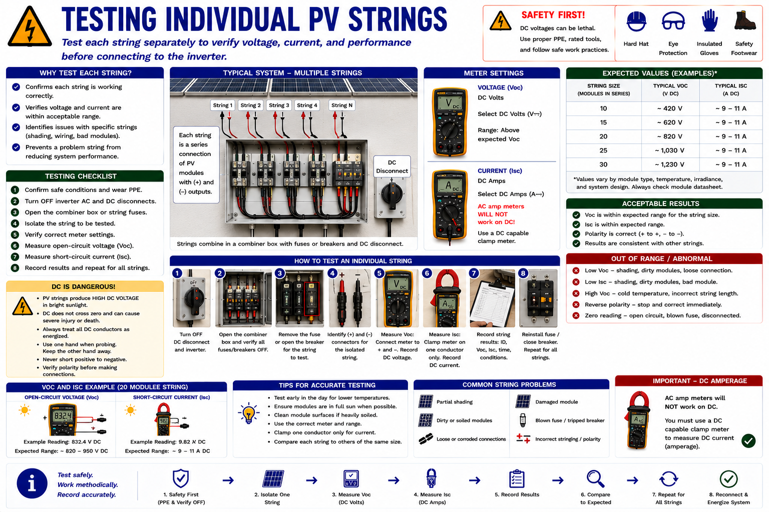
Compare Like With Like
String comparison is most useful when the circuits being compared are actually similar. Consider module count, module type, orientation, tilt, shading, irradiance, temperature, and MPPT configuration.
Similar Voltage
Comparable strings with similar module counts should normally have reasonably similar voltage under similar conditions.
One String at Zero Volts
May indicate an open circuit, disconnected string, open protective device, incorrect test point, or another interruption requiring investigation.
One String Significantly Low
May indicate a wiring, connection, module, bypass, configuration, or other string-level problem.
All Strings Abnormal
Look for a condition common to the strings rather than assuming several independent failures occurred simultaneously.
An Open Circuit Interrupts the Series Path
A PV string is a series circuit. A complete interruption anywhere in that path can prevent normal string current from flowing.
Possible causes include an unplugged or improperly seated connector, damaged conductor, open fuse, failed termination, damaged module connection, or another break in the series circuit.
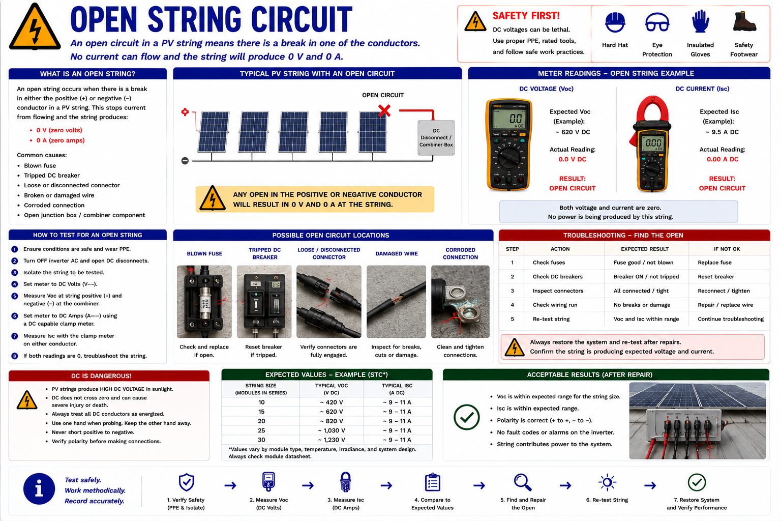
Use the Last Known-Good Point
If an individual string is abnormal, work through accessible test points in a controlled direction. The objective is to identify the location where the expected electrical condition changes.
A correct reading at one point followed by an abnormal reading at the next helps confine the fault to the conductors, connections, protective devices, or equipment between those locations.
Do not begin by disconnecting every module. Use the available circuit-level evidence to narrow the search before disturbing rooftop connectors or module wiring.
Use the String Design to Interpret the Meter Reading
The technician should compare measured string voltage with a reasonable expectation based on the installed modules and series count. This comparison is more useful than deciding that a voltage simply looks high or low.
The Pattern Matters
Near Expected Voltage
The series voltage path is substantially present, although voltage alone does not prove that the string can deliver normal current and power.
Zero or Near-Zero Voltage
Investigate an open circuit, disconnected conductors, protective devices, test location, or other major interruption.
Significantly Low Voltage
Compare the amount of missing voltage with module-level voltage and investigate the string configuration, connections, modules, and related equipment.
Unexpected Polarity
Stop and verify conductor identification, wiring, meter connections, and system configuration before proceeding.
Normal String Voltage Does Not Prove Normal String Output
A string may show a plausible open-circuit voltage while still being unable to deliver normal operating current. High-resistance connections, damaged components, shading, module problems, or other conditions may reduce useful power without eliminating open-circuit voltage.
Use voltage together with current, inverter operating data, environmental conditions, thermal findings, and comparisons with similar strings.
Current Helps Establish Whether the String Is Contributing
Where the system configuration and service procedure permit current measurement, use a properly rated DC-capable clamp meter. An AC-only clamp meter cannot correctly measure PV string DC current.
Zero or tare the DC clamp meter according to its manufacturer’s instructions before taking the measurement, and clamp around one conductor at a time.
Current Is Strongly Affected by Sunlight
Strings with similar orientation and equipment should generally produce comparable current when exposed to similar irradiance. A substantially lower current on one otherwise similar string can help identify an underperforming circuit.
Current comparisons are less useful when strings experience different shading, orientations, tilt angles, module types, or MPPT operating conditions. Record the environmental conditions when the measurements are taken.
A Circuit Can Be Connected and Still Perform Poorly
Not every DC fault is a complete open circuit. Loose, damaged, corroded, overheated, or poorly made connections can introduce resistance while leaving the electrical path partially intact.
These conditions may produce voltage drop, heating, intermittent operation, arcing, or reduced power. Combine electrical measurements with the visual and thermal inspection methods developed in Part II.
Do Not Assume Compatible-Looking Connectors Are Correct
PV connectors are critical parts of the DC circuit. Inspect for incomplete engagement, physical damage, overheating, contamination, moisture intrusion, poor strain relief, improper field assembly, and mismatched connector components.
Do not disconnect energized PV connectors under load unless the equipment and approved procedure specifically allow that operation. Follow manufacturer and site-specific isolation requirements.
Use the Combiner to Compare Strings
Where individual strings terminate in an accessible combiner box, the combiner can provide useful string-level test locations. It may also contain fuses, terminals, monitoring equipment, surge protection, or disconnecting means.
A normal combined output with one abnormal string reading can localize the problem to that string. Multiple abnormal strings may indicate a common array, combiner, environmental, or system configuration issue.
Know Which Strings Share the Same Tracker
Modern string inverters may contain multiple maximum power point trackers. Strings connected to different trackers may operate at different voltages or currents because they serve different array sections.
Do not compare two inverter inputs as though they should be identical until you have confirmed their module counts, array orientation, tracker assignments, and design.
System Architecture Can Change the Voltage You Expect
PV systems equipped with module-level rapid-shutdown equipment can present different voltage conditions depending on whether the rapid-shutdown system is active or released.
If measured voltage is much lower than expected, determine whether rapid shutdown or another control condition is intentionally limiting array voltage before diagnosing the wiring or modules as failed.
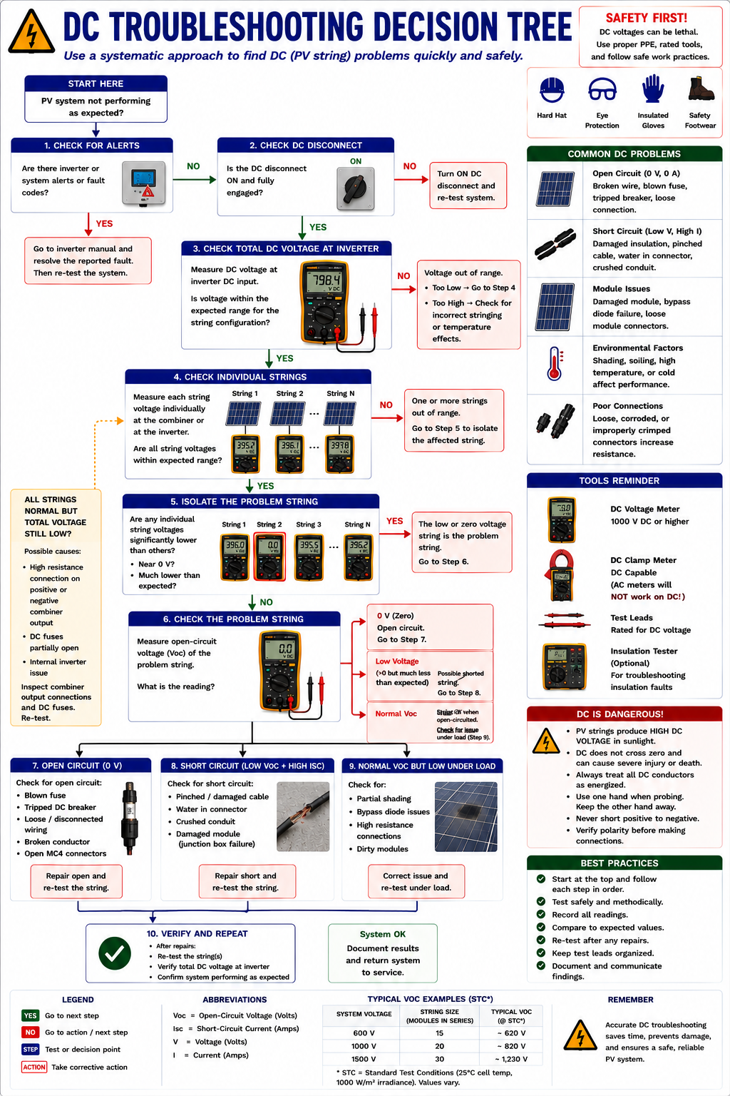
Let Each Measurement Determine the Next Step
Look Beyond the Basic String Circuit
If reasonable DC voltage and current are reaching the inverter but the inverter still does not produce expected AC output, the basic PV input circuit may not be the primary fault.
Review inverter status, faults, operating limits, MPPT behavior, controls, communications, temperature, manufacturer diagnostics, and other equipment-specific conditions before condemning components.
Localize the Investigation
If comparable strings are operating normally but one string is significantly different, concentrate the diagnosis on the abnormal circuit.
Review the string’s visual inspection findings, connectors, conductors, fuses, terminations, module count, polarity, shading, module condition, and other equipment associated specifically with that circuit.
Look for the Common Cause
When several independent strings show similar abnormal behavior, consider what they have in common.
Possible common factors include irradiance, widespread shading, rapid-shutdown state, common disconnects, combiner equipment, inverter input configuration, monitoring or control conditions, measurement method, or another shared system condition.
Troubleshooting principle: Multiple simultaneous symptoms often point toward a shared cause. Do not assume several independent components failed at the same time without evidence.
Investigate the String Under Operating Conditions
A string can produce reasonable open-circuit voltage yet underperform when current is required. Compare its current with similar strings and consider irradiance, shading, module condition, high-resistance connections, bypass behavior, and other conditions that affect loaded performance.
This is one reason voltage measurements should not be used alone to declare a PV string healthy.
Do Not Test Every Module Until the Circuit Points You There
Module-level testing is appropriate after the broader electrical measurements have narrowed the fault to a specific string or section of the array.
This reduces unnecessary rooftop work, avoids disturbing good connectors, and gives the technician a specific electrical problem to investigate rather than testing modules without a diagnostic objective.
Record Enough Information to Reconstruct the Diagnosis
Identify the Circuit
Record the inverter input, MPPT channel, combiner position, string number, or other circuit designation.
Record Voltage
Document the measured DC voltage, polarity, and test location.
Record Current
Where measured, record string or input current and the instrument used.
Record Environmental Conditions
Include time, irradiance or sunlight conditions, shading, and other factors affecting PV output.
Record the Expected Value
Document the module count, module rating, comparison string, or other basis used to interpret the measurement.
Record the Conclusion
State what the measurement establishes and what diagnostic step should follow.
PV Source Circuits Require Special Caution
PV modules can generate hazardous DC voltage whenever sufficient light reaches them. Unlike an ordinary load circuit, turning off the building AC supply does not remove the PV source.
DC arcs can also be persistent because direct current does not cross zero each cycle as AC does. Electrical testing should be performed only by qualified personnel using properly rated instruments, leads, PPE, isolation methods, and procedures appropriate for the installed system.
Never assume that opening a disconnect has de-energized conductors on both sides of that device. Establish the actual electrical condition before proceeding.
What You Should Take From This Lesson
Start at the Inverter
Determine whether reasonable DC voltage and current are reaching the inverter before moving into the array.
Know the Expected Voltage
Use module specifications, series module count, temperature, and system configuration to establish a reasonable string-voltage expectation.
Compare Similar Strings
Differences between otherwise similar circuits can quickly identify the portion of the array requiring further investigation.
Recognize an Open String
An interruption anywhere in the series path can prevent normal string current and remove that string’s contribution to the inverter.
Voltage Alone Is Not Enough
A plausible open-circuit voltage does not prove that the string can deliver normal operating current and power.
Look for Common Causes
If several strings show the same abnormal condition, investigate shared equipment and operating conditions before assuming multiple independent failures.
Move to Module Level Last
Use circuit-level testing to identify the affected string before testing individual modules or power optimizers.
Testing PV Modules and Power Optimizers
The next lesson moves from the string to the individual device level. It covers module test setup, open-circuit voltage, use of a PV module tester, optimizer testing, and the diagnostic differences between a module fault and an optimizer fault.
Electrical Testing and Troubleshooting
Return to the Part III landing page for the complete electrical testing and troubleshooting sequence.