Testing the AC Side of a PV System
The AC side is the logical starting point for electrical troubleshooting of a grid-connected PV system. Before moving into DC strings, modules, or optimizers, the technician should determine whether acceptable utility power is available and whether the inverter system is actually delivering AC power into the building electrical system.
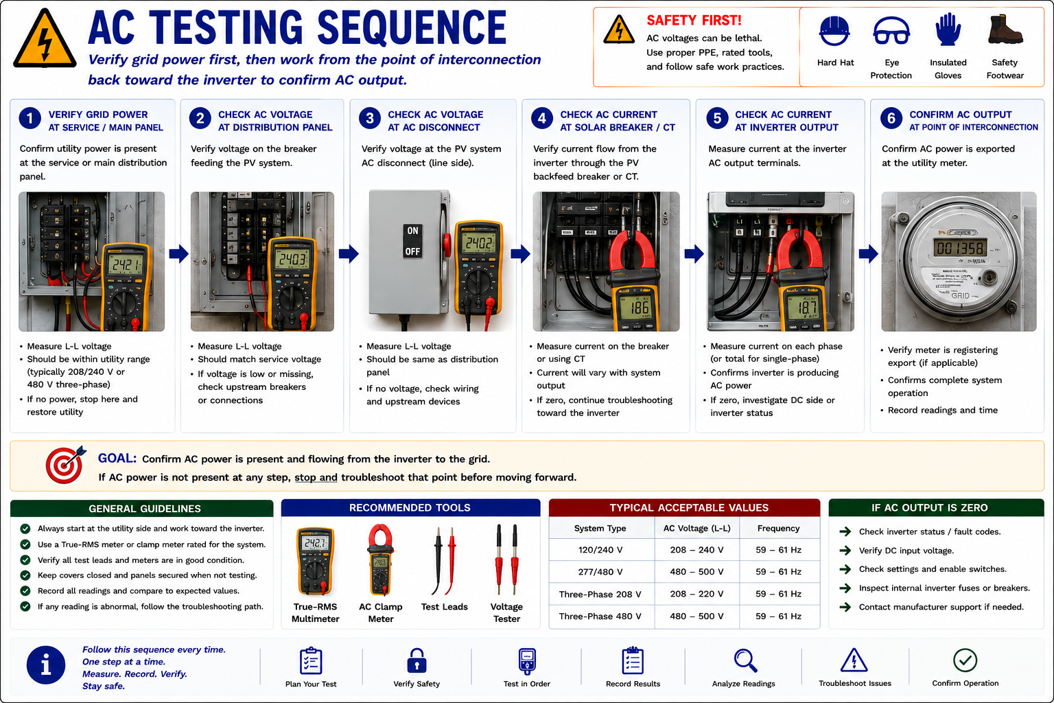
This lesson follows the AC circuit from the building distribution equipment toward the inverter. Voltage measurements establish whether the expected grid voltage is present. Current measurements establish whether PV-generated power is actually flowing. Each result determines the next diagnostic step.
Verify Grid Power First
A grid-interactive inverter cannot operate normally without acceptable utility AC conditions. If grid voltage is missing, significantly abnormal, or outside the inverter’s allowable operating range, the inverter may remain offline even when the PV array itself is functioning properly.
For this reason, troubleshooting should begin at the building electrical system and move toward the inverter. Confirm AC voltage, determine whether PV current is flowing, and identify the first location where the expected electrical condition is no longer present.
Know the System and Expected Values
Lesson 11 established the test plan. Before opening electrical equipment or touching meter probes to a circuit, identify the system voltage, inverter configuration, PV breaker, AC disconnect, conductor arrangement, utility connection, and expected operating conditions.
Review inverter status, fault codes, monitoring information, and available documentation before changing the system state.
Technician rule: Know what you expect before measuring. A number has limited diagnostic value unless you know what should reasonably be present at that location.
Work From the Utility Side Toward the Inverter
Verify Utility Power
Confirm that acceptable AC voltage is present at the service or main distribution equipment.
Check the PV Distribution Connection
Measure AC voltage at the circuit or breaker serving the PV system.
Measure PV AC Current
Determine whether current is flowing through the solar breaker or applicable current-sensing point.
Check the AC Disconnect
Confirm that expected AC voltage reaches the disconnect and continues through the circuit as intended.
Measure Inverter Output Current
Determine whether the inverter is actually delivering AC current under suitable operating conditions.
Interpret the Results
Use the combination of voltage, current, inverter status, and system conditions to determine the next troubleshooting step.
Voltage Establishes Whether the AC Source Is Present
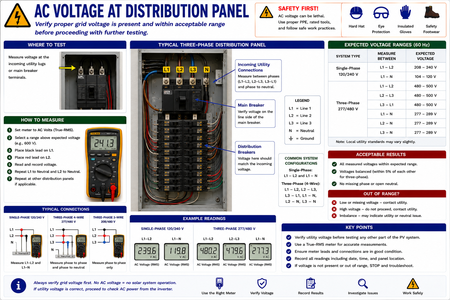
Use a properly rated meter set for AC voltage. The exact conductors to be measured depend on the building electrical system and inverter configuration.
On a typical single-phase 120/240-volt system, measurements may include line-to-line and line-to-neutral. Three-phase installations require the appropriate phase-to-phase and, where applicable, phase-to-neutral measurements.
Do not assume a voltage based only on equipment appearance. Use system documentation and nameplate information to establish the expected value.
Establish the AC Baseline
The building distribution equipment provides a useful starting point because it establishes whether normal utility voltage is available before the technician moves farther into the PV circuit.
If the expected voltage is not present at the distribution equipment, the problem must be resolved on the utility or building electrical side before normal grid-interactive inverter operation can be expected.
Verify All Required Conductors
Line-to-Line
Verify the expected voltage between the applicable line conductors.
Line-to-Neutral
Where the system uses a neutral, verify the appropriate line-to-neutral voltages.
Three-Phase Systems
Measure all required phase combinations rather than assuming one normal phase proves the entire service is normal.
Voltage Balance
Significant differences between comparable phases can indicate an AC supply or connection problem requiring further investigation.
No Acceptable Grid Voltage — Stop the PV Diagnosis Here
If the inverter does not have acceptable grid voltage available, moving immediately to the modules or DC strings does not address the primary operating requirement.
Resolve the missing or abnormal AC condition first, then continue the PV troubleshooting sequence.
Determine Whether PV Power Is Entering the Building
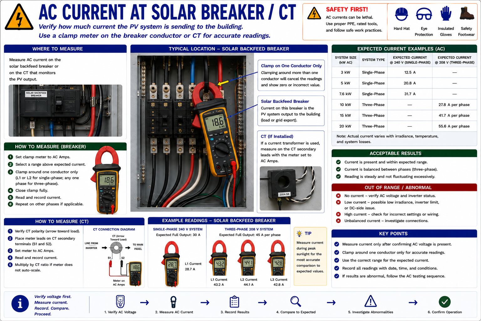
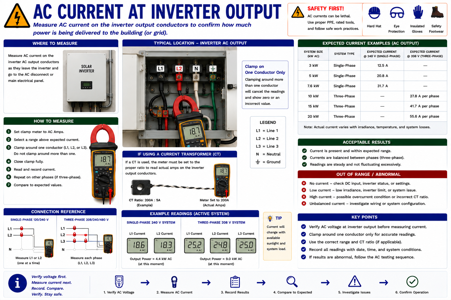
After confirming acceptable AC voltage, measure AC current on the conductor serving the PV backfed breaker or other applicable interconnection point.
Use an appropriately rated AC clamp meter and place the clamp around one current-carrying conductor at a time. Clamping around both outgoing and returning conductors can cause their magnetic fields to cancel and produce a near-zero or otherwise incorrect reading.
Current Must Be Evaluated Under Actual Operating Conditions
PV current varies with available solar energy and system operating conditions. A low current reading is not automatically evidence of an electrical failure.
Solar Irradiance
Clouds, haze, smoke, low sun angle, and seasonal conditions can reduce inverter output.
Shading
Partial array shading can significantly reduce available PV power.
System Size
Compare measured current with the actual inverter and system capacity rather than an arbitrary current value.
Inverter Operating State
Startup, derating, protective operation, curtailment, faults, or shutdown can reduce or eliminate AC output.
Voltage Does Not Prove Production
Utility voltage may be present at the inverter output terminals even when the inverter is producing no power.
AC current, inverter status, monitoring data, and operating conditions are needed to determine whether the PV system is actually delivering useful output.
Verify That Grid Voltage Reaches the Inverter Circuit
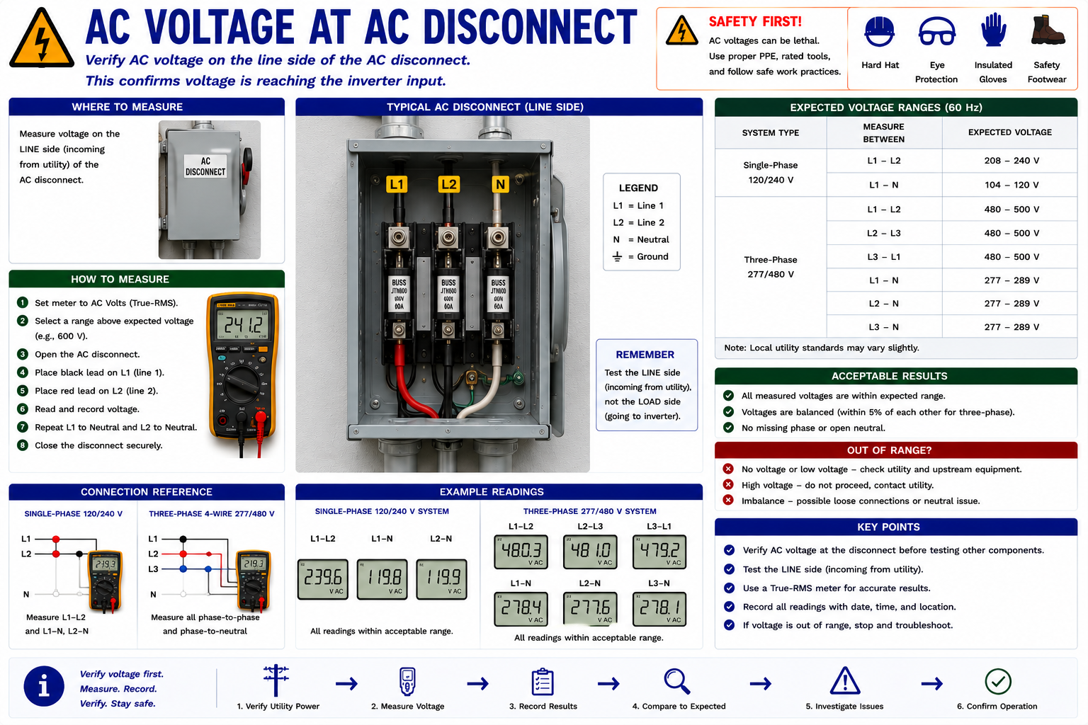
Where an external AC disconnect is present, the disconnect provides another useful test point between the distribution equipment and inverter.
Verify the expected voltage according to the equipment arrangement and safe-work procedure. If correct voltage exists upstream but not downstream where it should be present, investigate the disconnect, fuses where applicable, connections, and associated conductors.
Find the Point Where Normal Changes to Abnormal
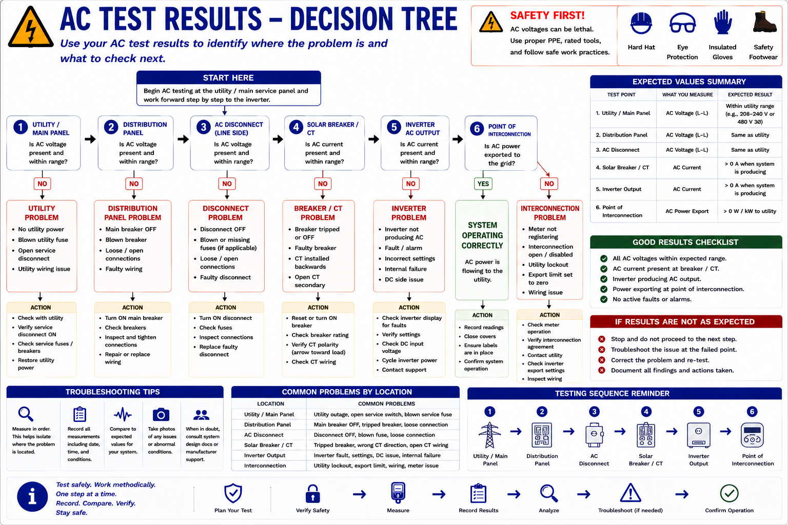
A systematic voltage check should move through the circuit in a known direction.
Known-Good Source
Confirm acceptable voltage at the utility or distribution side.
Next Device
Move to the next breaker, disconnect, fuse, termination, or accessible test point.
Compare
If the reading remains normal, continue toward the inverter.
Locate the Change
When an expected voltage disappears or becomes abnormal, concentrate the investigation between the last normal test point and the first abnormal one.
Determine Whether the Inverter Is Delivering Current
Once acceptable grid voltage has been verified at the inverter, measure AC output current under appropriate solar conditions.
Use the correct clamp meter technique and measure each required conductor or phase individually. Compare the reading with inverter monitoring, system size, environmental conditions, and expected operation.
Use Upstream and Downstream Measurements Together
Current at the inverter output and current at the building PV connection should be reasonably consistent for the same operating condition, allowing for system configuration and measurement method.
If the inverter produces current but the expected current is not present farther downstream, investigate the conductors, disconnects, breakers, fuses, terminations, and intermediate equipment between the two locations.
Measure All Required Conductors
Do not assume one normal reading establishes correct operation of an entire multi-conductor system.
On a single-phase system, confirm the required line conductors. On a three-phase system, compare all phases. Significant current imbalance or abnormal voltage relationships may indicate a connection, phase, utility, equipment, or configuration problem.
The Collection Circuit Is Already AC
Microinverter systems perform DC-to-AC conversion at or near the PV modules. The conductors leaving the array toward the collection equipment are therefore AC circuits.
Testing may include branch-circuit current, combiner or gateway equipment, PV breakers, and the building distribution connection.
Module-level monitoring is especially useful because one non-producing microinverter may be identified before roof-level electrical testing is required.
AC Results Tell You Whether to Move to the DC Side
On a string-inverter system, correct AC voltage with little or no inverter output does not by itself prove that the inverter has failed.
The next question is whether the inverter is receiving adequate DC input from the PV strings. Lesson 13 follows that diagnostic path.
Use the Measurements to Choose the Next Step
The AC Side Is Operating
If expected AC voltage is available and the inverter is delivering current consistent with the conditions, the AC portion of the system is functioning.
If the original complaint is low overall production, continue by comparing actual output with expected production and, when necessary, investigate the DC strings or module-level system.
The Inverter Has Grid Power but Is Not Delivering Output
Correct grid voltage with little or no inverter output means additional diagnosis is required.
Check Inverter Status
Review active faults, warnings, operating mode, event history, and display information.
Check Solar Conditions
Confirm that sufficient irradiance is available for meaningful production.
Check DC Input
On a string-inverter system, proceed to DC testing to determine whether the PV strings are supplying the inverter.
Check Controls and Communications
Rapid shutdown, remote controls, hybrid operating modes, or manufacturer-specific conditions may prevent normal output.
Stay on the AC Side
If expected AC voltage is absent, troubleshoot the AC circuit before investigating the PV strings.
Check the utility supply, distribution equipment, PV breaker, disconnect, fuses where applicable, conductors, connections, and other devices between the last known-good test point and the location where voltage is missing.
Investigate the Grid or AC Circuit
High, low, missing, or significantly unbalanced AC voltage can prevent a grid-connected inverter from operating normally.
Determine whether the abnormal condition originates with the utility, building distribution system, circuit wiring, disconnect equipment, or a local connection before proceeding to array-side diagnosis.
No AC Output Has Several Possible Causes
An inverter with no AC output may be responding correctly to another problem. It may lack acceptable grid voltage, lack adequate DC input, have an active fault, be in rapid shutdown, be waiting through a startup delay, be operating under a control condition, or have another system-level issue.
Verify the required inputs and operating conditions before deciding that the inverter itself has failed.
Voltage and Current Provide a Reasonableness Check
For an appropriate single-phase measurement, a quick apparent-power estimate can be obtained by multiplying voltage by current.
Apparent Power ≈ Voltage × Current
For example, approximately 240 volts and 20 amperes represent roughly 4,800 volt-amperes.
Use inverter monitoring or appropriate power-measurement equipment when accurate real-power measurement is required. The simple calculation is primarily a quick field reasonableness check.
Independent Evidence Should Make Sense Together
Compare field measurements with inverter displays, monitoring portals, utility or production meters, and other available system information.
If monitoring reports substantial production while field current measurements indicate no output, investigate the discrepancy rather than assuming either source is automatically correct.
A disagreement can point toward monitoring, metering, current-transformer, communications, configuration, or measurement problems.
Record the Conditions Along With the Reading
Test Location
Identify exactly where the measurement was taken.
Measurement
Record voltage or current and identify the conductors involved.
Time and Weather
Record the conditions affecting PV production at the time of the test.
Inverter Status
Record operating mode, active faults, warnings, and monitoring information.
Expected Value
Document the rating or comparison information used to interpret the measurement.
Next Action
State what the test result proves and where the diagnostic sequence should move next.
AC Distribution Equipment Can Contain Lethal Energy
Distribution panels, PV breakers, AC disconnects, inverter terminals, combiner equipment, and utility-connected conductors can remain energized from the electrical grid. PV generation and battery systems can introduce additional electrical sources.
Electrical measurements should be performed only by qualified personnel using appropriately rated meters, leads, clamps, PPE, and safe-work procedures. Follow the requirements and manufacturer instructions applicable to the installed equipment and work environment.
What You Should Take From This Lesson
Start With Grid Power
Verify acceptable AC voltage before assuming that a non-producing inverter has failed.
Measure Voltage Systematically
Work from the distribution equipment toward the inverter and identify where an expected voltage changes or disappears.
Measure Current to Confirm Output
Utility voltage can be present even when the inverter is producing nothing. AC current helps establish whether PV power is actually flowing.
Clamp Around One Conductor
Use an appropriately rated AC clamp meter on one current-carrying conductor at a time.
Consider Solar Conditions
Current must be interpreted in relation to irradiance, shading, system size, inverter state, and other operating conditions.
Use the Result to Choose the Next Test
If the AC circuit is normal but a string inverter produces little or no output, proceed to the DC side rather than immediately replacing the inverter.
Testing the DC Side of String-Inverter Systems
The next lesson moves to the array side of the inverter. It examines DC voltage at the inverter, individual string measurements, open-string faults, expected versus measured string voltage, and the decision process used to localize an abnormal DC circuit.
Electrical Testing and Troubleshooting
Return to the Part III landing page for the complete electrical testing and troubleshooting sequence.