Testing PV Modules and Power Optimizers
Module-level testing should normally come after the broader PV circuit has been evaluated. AC-side testing establishes whether the inverter can operate with the utility system, and DC string testing determines whether the array is delivering reasonable voltage and current to the inverter. Only after those tests have localized an abnormal condition should the technician move deeper into the array.
This lesson examines individual PV module testing and power optimizer diagnosis. The objective is not to test every module in the array. It is to use measurements and system information to distinguish a module problem from an optimizer, connection, wiring, or other localized fault.
Move to Module Level Only After Localizing the Problem
A large PV array may contain dozens or hundreds of modules and many electrical connections. Beginning a troubleshooting call by individually testing modules is inefficient and can unnecessarily disturb connectors and wiring that were functioning normally.
The diagnostic process should narrow the problem first. If string testing identifies one abnormal circuit, monitoring identifies one underperforming module, or other evidence points toward a particular section of the array, module-level testing becomes a targeted diagnostic procedure.
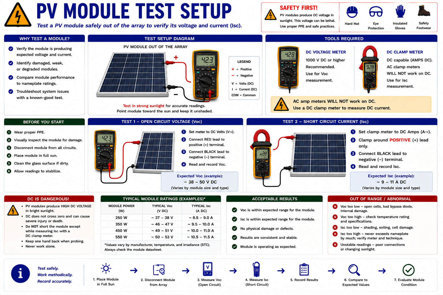
Know Why You Are Testing the Module
Every module-level measurement should answer a specific diagnostic question. The technician should already know what abnormal condition led to the module and what measurement is expected.
Identify the Suspect Circuit
Use inverter information, monitoring data, string measurements, visual inspection, or thermal findings to identify the affected string or module location.
Review Module Specifications
Determine the module’s rated open-circuit voltage, short-circuit current, operating voltage, operating current, and other relevant specifications.
Identify Module-Level Electronics
Determine whether the module connects directly into a string or through a power optimizer, microinverter, rapid-shutdown device, or other module-level equipment.
Establish Safe Isolation
Follow the approved shutdown, isolation, and testing procedure for the installed equipment before disturbing connectors or conductors.
Record Environmental Conditions
Module electrical performance depends on irradiance, temperature, shading, and other field conditions.
Do Not Create a Second Problem While Looking for the First
Every connector that is separated and every conductor that is disturbed introduces an opportunity for damage, contamination, incomplete engagement, incorrect reconnection, or another service-created fault.
Use electrical evidence to narrow the diagnosis before disconnecting equipment unnecessarily.
Establish the Electrical Values You Expect
Module specifications provide the reference values needed to interpret electrical measurements. Common ratings include open-circuit voltage (Voc), short-circuit current (Isc), voltage at maximum power (Vmp), current at maximum power (Imp), and maximum power (Pmax).
These ratings are established under specified test conditions. Field measurements will vary with irradiance, cell temperature, angle of incidence, shading, module condition, and test method.
Voc
Open-circuit voltage measured when the module is illuminated but not supplying current to a load.
Isc
Short-circuit current under specified conditions. This measurement requires an appropriate procedure and properly rated test equipment.
Vmp
The module voltage at its rated maximum-power operating point under the specified test conditions.
Imp
The module current at its rated maximum-power operating point under the specified test conditions.
Pmax
The rated maximum power of the module under the manufacturer’s specified test conditions.
Measure Module Voc
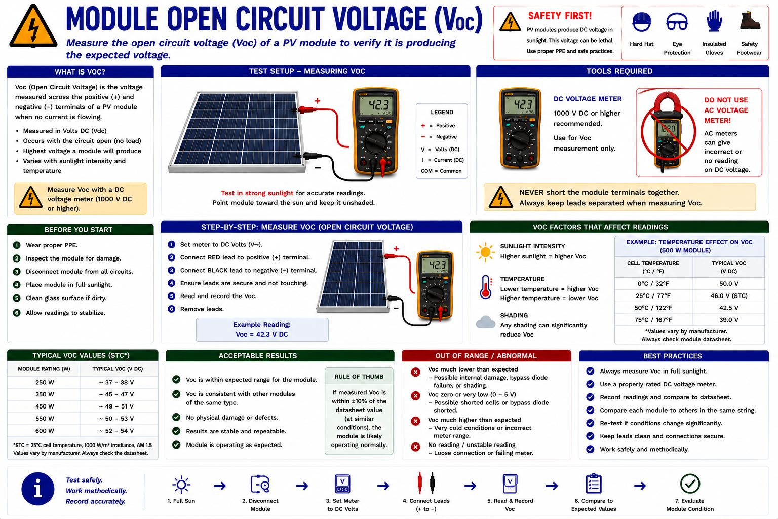
Open-circuit voltage is one of the basic module-level measurements. With the module appropriately isolated according to the equipment and service procedure, a properly rated DC voltmeter is connected across the module output to measure polarity and open-circuit voltage.
Before connecting the meter, confirm that the instrument is configured for DC voltage and that its voltage rating exceeds the maximum voltage that could be encountered.
Compare the Reading With the Module Specification
A reasonable Voc reading establishes that the module is generating DC voltage, but the exact value should not be expected to match the nameplate under every field condition.
Module temperature has a particularly important effect on voltage. Hot modules generally produce lower voltage than the same modules under colder conditions.
Important: A normal open-circuit voltage does not prove that the module can produce normal current or power under load.
Use the Measurement as Evidence
Reasonable Voc
The module is generating voltage. Continue the diagnosis if production remains abnormal.
Zero or Near-Zero Voltage
Verify the test setup, connections, illumination, and module configuration before considering an internal module fault.
Unexpectedly Low Voltage
Consider module condition, internal electrical paths, bypass behavior, temperature, shading, connections, and test conditions.
Reverse Polarity
Stop and verify conductor identification, test-lead orientation, connections, and system configuration before proceeding.
Voltage Alone Cannot Fully Evaluate a PV Module
A voltmeter places very little electrical load on the module. As a result, a module can sometimes produce plausible open-circuit voltage while failing to deliver normal current or power under operating conditions.
When a more complete performance evaluation is required, a PV module tester or analyzer can provide additional information about module behavior.
Evaluate More Than Open-Circuit Voltage
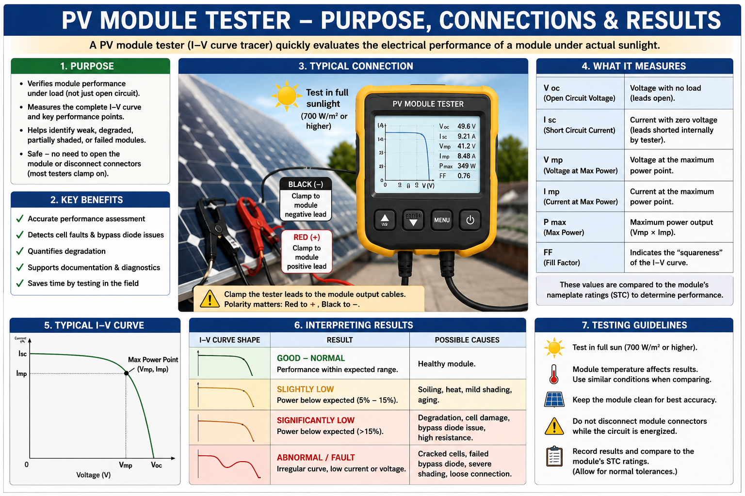
PV-specific test instruments can evaluate module or string electrical performance more comprehensively than a basic voltmeter. Depending on the instrument, measurements may include Voc, Isc, operating characteristics, maximum-power information, and current-voltage curve data.
Always confirm the tester’s voltage, current, and power ratings before connecting it to a PV source. Follow the tester manufacturer’s connection and operating procedure.
A Module Is a Power Source, Not Just a Voltage Source
The useful output of a PV module depends on both voltage and current. A complete performance evaluation therefore considers how the module behaves while delivering current, not simply the voltage measured with no load connected.
PV analyzers that evaluate the module’s current-voltage behavior can reveal performance problems that may not be obvious from a Voc measurement alone.
Use a Known-Good Neighbor as a Reference
When modules of the same type are installed next to one another with similar orientation, temperature, and irradiance, a nearby normally operating module can provide a useful comparison.
If one module produces substantially different electrical results from otherwise comparable neighboring modules, the difference becomes important diagnostic evidence.
Compare like with like: Module comparisons are most useful when the modules have similar specifications and are experiencing similar sunlight, shading, orientation, and temperature.
Combine Electrical Testing With the Inspection Findings
Return to the visual and thermal information developed in Part II. Cracked glass, damaged backsheets, burned connectors, moisture intrusion, discoloration, hot spots, damaged wiring, or mounting problems can provide context for an abnormal electrical measurement.
The strongest diagnosis often comes from several independent observations pointing toward the same component or circuit.
The Module May Not Connect Directly to the String
Power-optimizer systems add module-level electronics between each PV module and the inverter-side DC circuit. The optimizer receives power from the module and controls its output according to the system design.
This changes the troubleshooting process because an abnormal module-level result can originate with the module, optimizer, connectors, communications, wiring, system controls, or inverter interaction.
Use Module-Level Data Before Going to the Roof
Optimizer systems commonly provide module-level monitoring. Review that information before disturbing rooftop equipment.
Look for a single non-producing device, persistent underperformance, intermittent operation, communications loss, repeated faults, or a group of devices showing the same symptom.
The pattern can help distinguish a localized device problem from a common system-level condition.
Follow a Controlled Diagnostic Sequence
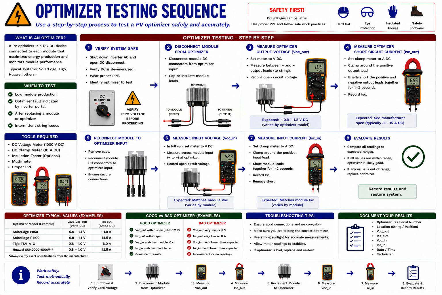
Review Monitoring
Identify the affected optimizer and compare its production and communications history with neighboring devices.
Verify System Conditions
Confirm that the system is in the correct operating state and that rapid shutdown, communications, inverter operation, or another common condition is not causing the symptom.
Inspect the Location
Check the module, optimizer, connectors, conductors, mounting, and surrounding area for visible or thermal evidence.
Evaluate the Module
Where the approved procedure permits isolation, determine whether the module is supplying reasonable electrical input to the optimizer.
Evaluate the Optimizer
Use manufacturer-specific diagnostic information and electrical measurements appropriate for the installed optimizer.
Verify the Repair
After correction, confirm communications, production, system status, and module-level monitoring.
Do Not Assume All Optimizers Behave the Same Way
Power optimizers can produce manufacturer-specific output voltages or operating states during shutdown, startup, pairing, rapid shutdown, communications loss, or normal operation.
Use the manufacturer’s service documentation to establish the expected electrical behavior before deciding that an optimizer output measurement is abnormal.
Separate the Two Components Diagnostically
When one optimizer location is underperforming, the technician must determine whether the PV module feeding the optimizer is abnormal or whether the optimizer itself is failing to process otherwise normal module output.
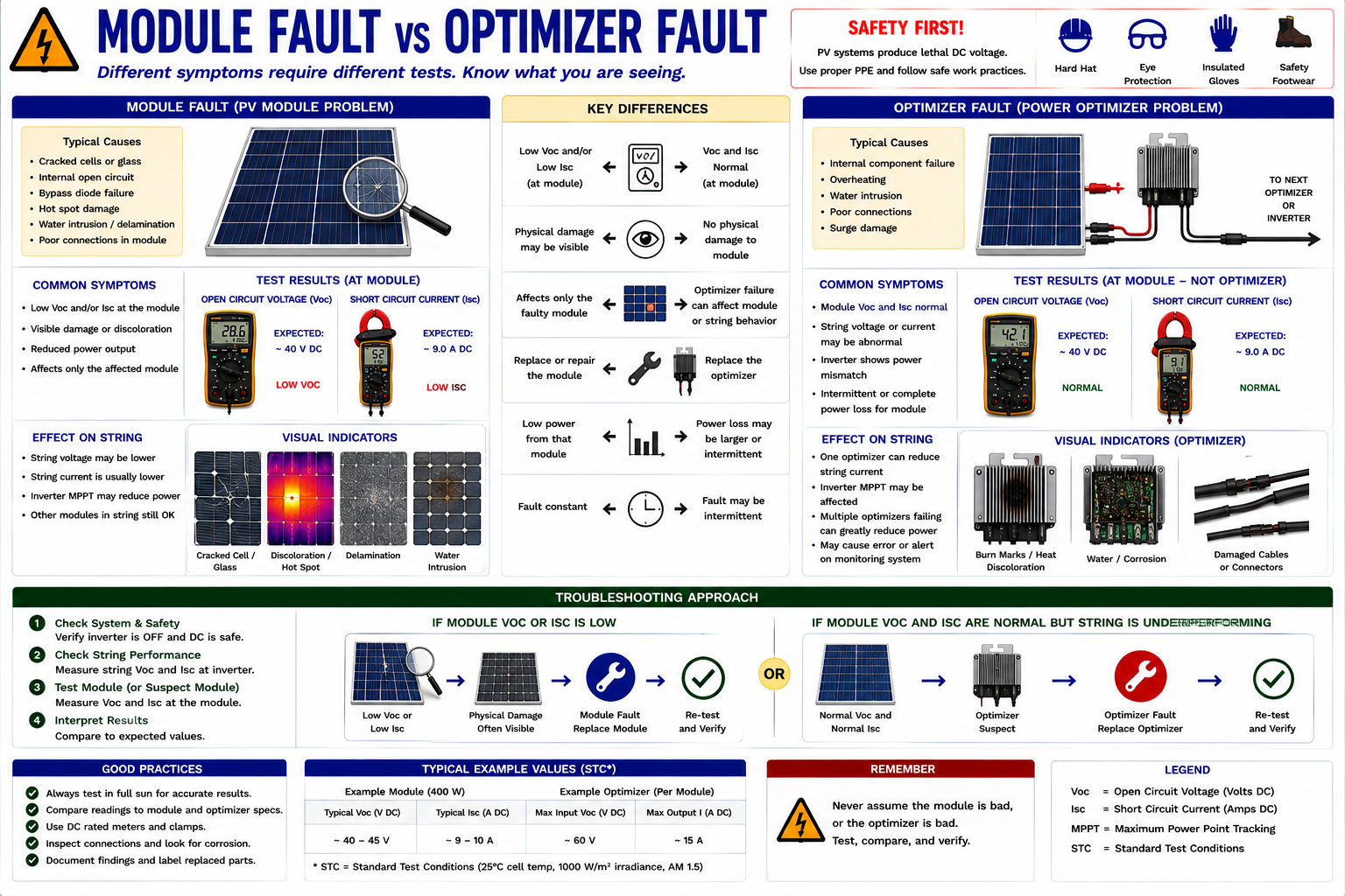
Abnormal Input Points Toward the Module Side
If monitoring identifies one underperforming location and direct evaluation shows that the associated module itself has abnormal electrical output under comparable conditions, the evidence points toward the module or its immediate connections.
Continue to consider shading, contamination, module temperature, physical damage, connectors, conductors, and test conditions before condemning the module.
Normal Module Input With Abnormal Device Behavior Changes the Diagnosis
If the module provides reasonable electrical input but the optimizer does not behave as expected, the optimizer, its output connections, communications, configuration, or related system controls become stronger suspects.
Confirm the expected optimizer behavior from the manufacturer before replacement.
No Monitoring Data Does Not Automatically Mean No Power
A module-level device can experience a communications problem without necessarily having the same electrical failure. Conversely, a device may communicate while producing little or no useful power.
Distinguish communications status from electrical production. Use both types of information rather than treating one as proof of the other.
Look for a Shared Cause
If several optimizers become unavailable at the same time, consider a common condition before assuming that several devices failed independently.
Inverter Condition
A shutdown, fault, or configuration issue may affect many module-level devices.
Rapid Shutdown
The system may intentionally place module-level equipment into a reduced-output state.
Communications
A shared communications problem may make multiple devices appear unavailable.
String Wiring
A common string connection or circuit problem may affect multiple devices downstream or upstream of the fault.
Do Not Replace a Component Until the Evidence Supports It
Module and optimizer replacement can require significant rooftop work. A replacement decision should therefore be based on a repeatable diagnosis rather than a single unexplained reading or monitoring alert.
Confirm the expected input, expected output or device state, wiring and connector condition, communications status where applicable, environmental conditions, and manufacturer diagnostic information before concluding that the component itself has failed.
Verify the Entire Diagnostic Chain
Replacing a failed module or optimizer is not the end of the troubleshooting process. Restore the system according to the approved procedure and verify that the original symptom has actually been corrected.
Inspect the Repair
Confirm connector engagement, conductor routing, mounting, equipment security, and workmanship.
Restore the System
Follow the required startup sequence for the inverter and module-level equipment.
Check Device Status
Verify that the repaired location communicates and operates as expected where monitoring is available.
Verify Electrical Operation
Confirm that the affected string or module now produces reasonable electrical results.
Verify System Production
Confirm that inverter and system-level production are consistent with current operating conditions.
Record the Evidence and the Repair
Document the module or optimizer identification, location, serial number where applicable, monitoring findings, electrical measurements, environmental conditions, visual or thermal findings, diagnosis, repair performed, and final verification results.
Module-level documentation is especially important because future technicians may need to correlate production history with a particular physical location in the array.
Module-Level Work Still Involves an Active Energy Source
An illuminated PV module can generate voltage whenever sufficient light reaches it. Opening an AC breaker does not remove the module’s DC source voltage, and module-level electronics can create equipment-specific electrical conditions.
Use properly rated test equipment, PPE, manufacturer procedures, approved isolation methods, and safe work practices. Do not disconnect PV connectors under load unless the installed equipment and approved procedure specifically permit it.
What You Should Take From This Lesson
Localize Before Testing Modules
Use AC, DC string, monitoring, visual, and thermal evidence to narrow the problem before disturbing module-level equipment.
Know the Module Ratings
Use Voc, Isc, Vmp, Imp, Pmax, and manufacturer information to establish reasonable expectations.
Voc Is Only One Measurement
Normal open-circuit voltage does not prove that a module can deliver normal operating current or power.
Use PV-Specific Test Equipment When Needed
A module tester can provide more complete performance information when a voltmeter alone cannot answer the diagnostic question.
Use Monitoring First on Optimizer Systems
Module-level data can identify the suspect location before rooftop electrical testing begins.
Separate Module and Optimizer Behavior
Determine whether the optimizer is receiving reasonable module input before deciding which component has failed.
Verify the Repair
Restore the system and confirm electrical operation, communications, monitoring, and system production before closing the service call.
Systematic PV System Diagnosis
The final lesson in Part III combines AC testing, DC string testing, module-level diagnosis, monitoring information, visual inspection, and troubleshooting logic into a repeatable diagnostic process for common PV system complaints.
Electrical Testing and Troubleshooting
Return to the Part III landing page for the complete electrical testing and troubleshooting sequence.