Split Systems With Air Handlers
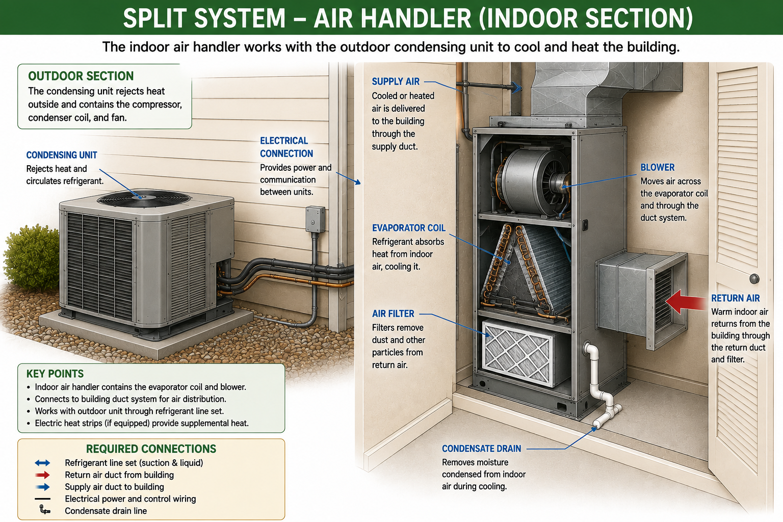
A split air-conditioning system divides the equipment between outdoor and indoor assemblies. In the configuration covered in this lesson, an outdoor condensing unit is connected by refrigerant piping to an indoor air handler containing the evaporator coil, blower, filter arrangement, and other equipment needed to condition and circulate building air.
This is one of the most common central air-conditioning configurations. Rather than reviewing the refrigeration components individually, this lesson concentrates on recognizing the complete installation, understanding how the outdoor unit and indoor air handler work together, and following the path of building air through the indoor equipment.
Learning Objectives
Recognize the Split Configuration
Identify a conventional split system by recognizing its separate outdoor condensing unit and indoor air handler.
Identify the Connections
Recognize the refrigerant line set, electrical connections, condensate drain, supply duct, and return duct associated with the system.
Follow Building Airflow
Trace return air through the filter, evaporator coil, blower, and optional electric heating section before the conditioned air enters the supply duct.
Recognize Common Installations
Understand that air handlers can be installed in several building locations and orientations while still performing the same basic functions.
Indoor and Outdoor Equipment Work Together
The term split system describes an air-conditioning or heat-pump system in which the refrigeration equipment is divided between separate indoor and outdoor assemblies. Refrigerant piping connects those assemblies so they operate together as one complete system.
In the air-handler configuration, the outdoor condensing unit is located outside the conditioned building while the air handler is located indoors or within another protected building space. The outdoor unit and air handler are not independent appliances. They are parts of the same refrigeration and air-conditioning system.
The Condensing Equipment Is Outside
The outdoor portion of a conventional split air conditioner contains the condensing equipment previously studied in this course. During cooling operation, heat absorbed from the building is ultimately rejected to outdoor air at this unit.
Because the detailed operation of the compressor and condenser has already been covered, the important point here is location: these components are physically separated from the indoor evaporator and air-moving equipment.
Use the Existing Component Lessons
If you need to review how the outdoor refrigeration components operate, return to the appropriate compressor and condenser lessons in Air Conditioning & Refrigeration. This lesson concentrates on system configuration rather than repeating component operation.
The Air Handler Conditions and Moves Building Air
The air handler provides the indoor portion of this split-system configuration. It contains the evaporator coil and blower and provides the physical connection between the refrigeration system and the building’s air-distribution system.
Depending on the equipment design, the air handler may also contain electric resistance heating elements. These can provide the heating source for some systems or serve as supplemental or auxiliary heat when the air handler is used with heat-pump equipment.
Evaporator Coil
During cooling, building air passes across the evaporator coil where heat is transferred from the air to the refrigerant and moisture may condense from the air.
Blower
The blower produces the airflow needed to pull return air through the indoor equipment and move conditioned air into the supply duct system.
Filter
The return-air filter removes airborne material before the air passes through the indoor equipment and helps protect the coil and blower from contamination.
Optional Electric Heat
Some air handlers contain electric resistance heating elements that can provide or supplement building heat depending on the system design.
Return Air In — Conditioned Air Out
The building air path is separate from the refrigerant path. Air from the occupied space travels through the return duct and enters the air handler. In the typical upflow arrangement illustrated in this lesson, the return air first passes through the filter and then moves upward through the evaporator coil.
After passing through the coil, the air enters the blower. The blower then pushes the air toward the supply side of the air handler. If electric resistance heating elements are installed and energized, the air passes across those elements before entering the supply duct.
Return Air
Air from the conditioned building enters the indoor equipment through the return duct.
Filter
The returning air passes through the air filter before reaching the evaporator coil and blower.
Evaporator Coil
During cooling, the air passes through the evaporator coil where sensible heat and moisture can be removed from the air.
Blower
The blower moves the conditioned air toward the supply side of the air handler.
Electric Heat When Used
If electric heating elements are installed and operating, the blower pushes air across the elements before the air leaves the unit.
Supply Air
Conditioned air leaves the air handler through the supply duct and is distributed throughout the building.
Two Refrigerant Lines Connect the Equipment
The indoor evaporator and outdoor condensing unit are connected by a refrigerant line set. In a conventional split air-conditioning system, this consists of two refrigerant tubes connecting the indoor and outdoor equipment.
The larger vapor line is normally insulated, while the smaller liquid line is normally not insulated in a conventional air-conditioning installation. The exact tubing sizes, allowable lengths, insulation requirements, vertical-rise considerations, and other installation requirements depend on the equipment and application.
Line Sets Are Already Covered in Detail
This course has a complete section devoted to refrigerant line sets, including sizing, oil return, vertical risers, insulation, fittings, equivalent length, ductless piping, brazing, pressure testing, evacuation, and installation practices. Refer to Refrigerant Line Sets in Split Systems rather than treating this brief overview as installation instruction.
Cooling Can Produce Water at the Indoor Coil
When the evaporator coil operates below the dew-point temperature of the entering air, moisture condenses on the coil. That water collects in the condensate pan beneath the evaporator coil and must be carried away through the condensate drainage system.
The condensate drain is therefore another useful clue when identifying indoor cooling equipment. Depending on the installation, gravity drainage may carry the condensate to an approved disposal location or a condensate pump may be required.
Condensate Comes From the Coil Area
The primary condensate connection is associated with the evaporator coil and its drain pan. When examining an air handler, look for the condensate piping at or immediately below the evaporator-coil section rather than treating it as an arbitrary cabinet drain.
The Indoor Equipment Can Be Located in Several Places
Unlike the outdoor condensing unit, the air handler is normally installed indoors or in another location appropriate for the equipment and climate. Building design often determines the most practical location.
Mechanical Room
A dedicated mechanical space can provide convenient access to the equipment, ductwork, electrical service, and condensate drainage.
Utility Closet
Residential air handlers are frequently installed in closets when floor plans and duct arrangements permit.
Basement
Buildings with basements may locate the air handler near the main supply and return duct system.
Attic
Air handlers may also be installed in attics when the equipment is approved for the orientation and appropriate access, drainage, insulation, and installation provisions are provided.
Not Every Air Handler Is Installed Vertically
This lesson uses an upflow air handler because it clearly illustrates the airflow sequence. Actual equipment may be designed for upflow, downflow, horizontal, or multiple-position installation. Always follow the equipment manufacturer’s approved orientation and installation instructions.
Do Not Call Every Indoor Cabinet a Furnace
Beginning technicians sometimes use the word furnace for any large indoor HVAC cabinet. That terminology is incorrect. An air handler and a gas furnace can both contain blowers and connect to ductwork, but they are different types of equipment.
An air handler does not require a gas-fired furnace section. It commonly contains the evaporator coil and blower and may contain electric heating elements. A gas furnace contains gas-heating equipment and can be paired with a separate evaporator coil to provide cooling.
The next lesson will examine the split-system arrangement that uses a gas furnace with an evaporator coil installed above it.
What Should You Look For?
Outdoor Condensing Unit
Look for a separate outdoor refrigeration unit rather than a large packaged cabinet connected directly to the building ductwork.
Two Refrigerant Lines
Look for the line set connecting the outdoor condensing unit to the indoor equipment, typically including a larger insulated vapor line and smaller liquid line.
Indoor Air Handler
Look for an indoor cabinet connected to the building’s return and supply ducts and containing the evaporator and blower sections.
Condensate Drain
Look for condensate piping leaving the evaporator-coil drain-pan area of the indoor equipment.
No Gas Furnace Required
An air-handler system does not require a gas furnace. Heating may be electric or may be provided by a heat-pump configuration or another system design.
Supply and Return Ductwork
The air handler is part of a central forced-air system and normally connects directly to the building’s supply and return duct system.
Avoid These Identification Mistakes
“The Outdoor Unit Is the Air Conditioner”
Incomplete. In a split system, the outdoor unit is only one assembly. The indoor coil, air handler, refrigerant piping, controls, and duct system are also parts of the complete installation.
“An Air Handler Is a Furnace”
Incorrect. An air handler provides indoor air-moving and conditioning functions but does not automatically contain a gas-fired furnace.
“A Split System Has Two Complete Air Conditioners”
Incorrect. The indoor and outdoor assemblies are different portions of one complete refrigeration system.
“The Two Refrigerant Lines Do the Same Thing”
Incorrect. The two lines carry refrigerant under different conditions and perform different functions within the refrigeration circuit.
“The Condensate Drain Can Leave Anywhere on the Cabinet”
Incorrect. Condensate is collected at the evaporator-coil drain pan, so the primary condensate connection is associated with that section of the equipment.
“All Air Handlers Have the Same Orientation”
Incorrect. Depending on the equipment design, air handlers may be installed in upflow, downflow, horizontal, or other manufacturer-approved configurations.
Review Questions
1. Why is this type of equipment called a split system?
Answer: The refrigeration equipment is divided between separate indoor and outdoor assemblies that are connected by refrigerant piping.
2. What is the indoor assembly in the configuration covered by this lesson?
Answer: An air handler containing the indoor evaporator coil, blower, filter arrangement, and other equipment required for the particular system.
3. What connects the indoor and outdoor refrigeration equipment?
Answer: A refrigerant line set containing two refrigerant lines connects the indoor and outdoor assemblies.
4. In the upflow arrangement discussed in this lesson, what is the basic building-air path?
Answer: Return duct → filter → evaporator coil → blower → optional electric heat → supply duct.
5. Why is there a condensate drain at the indoor equipment?
Answer: Moisture can condense from the building air on the cold evaporator coil during cooling. The condensate pan collects that water and the drainage system carries it away.
6. Is an air handler the same thing as a gas furnace?
Answer: No. Both can contain blowers and connect to duct systems, but an air handler does not automatically contain gas-fired heating equipment.
7. Where might an air handler be installed?
Answer: Depending on the equipment and building, common locations include mechanical rooms, utility closets, basements, and attics.
8. Does every air handler have to be installed in the upflow position?
Answer: No. Equipment may be designed for upflow, downflow, horizontal, or multiple-position installation. The manufacturer’s instructions determine the approved orientations.
Lesson 4 Summary
- A split system divides the refrigeration equipment between separate indoor and outdoor assemblies connected by refrigerant piping.
- The configuration covered in this lesson uses an outdoor condensing unit and an indoor air handler.
- The air handler contains the indoor evaporator coil and blower and connects to the building’s supply and return duct system.
- An air handler may also contain electric resistance heating elements depending on the system design.
- In the upflow arrangement discussed here, building air travels from the return duct through the filter and evaporator coil, into the blower, across optional electric heat, and into the supply duct.
- The outdoor and indoor equipment are connected by a two-line refrigerant line set.
- The larger vapor line is normally insulated in a conventional air-conditioning installation.
- Condensate produced at the evaporator coil collects in a drain pan and must be removed through an appropriate drainage system.
- Air handlers can be installed in mechanical rooms, closets, basements, attics, and other approved locations.
- Air handlers may be designed for several airflow orientations and are not limited to upflow installations.
- An air handler is not the same thing as a gas furnace.
- The outdoor condensing unit alone is not the complete air-conditioning system.