BASIC ELECTRICAL FOR THE HVAC TECHNICIAN
Source, Switch, Path and Load
Understanding the basic parts of a circuit and how
series and parallel arrangements change circuit behavior.
The circuits you have worked with so far are simple,
but the same basic ideas continue to apply as circuits
become more complicated.
Why This Matters
When you troubleshoot an electrical circuit, one of the
first things you should be able to do is identify the
source, the conductive path, the control devices, and
the loads.
Once you know what each part is supposed to do, you can
begin tracing the circuit logically instead of guessing.
This becomes especially important when circuits contain
multiple switches, multiple loads, or more than one
current path.
The Four Basic Parts
The basic circuit model we have been using is:
Source
→
Switch / Control
→
Path
→
Load
→
Return to Source
Source
The source provides the electrical potential
that makes current flow possible.
Examples include a battery, utility power,
or the secondary of a transformer.
Switch / Control
A switch or control opens or closes an intended
circuit path.
In HVAC equipment, this might be a thermostat,
relay contact, pressure switch, safety switch,
or electronic control.
Path
The path is the conductive route through which
current can flow.
Wires, terminals, contacts, and other conductive
parts form the path.
Load
The load uses electrical energy to perform work.
Motors, heaters, lamps, relay coils, contactor coils
and compressor windings are examples of loads.
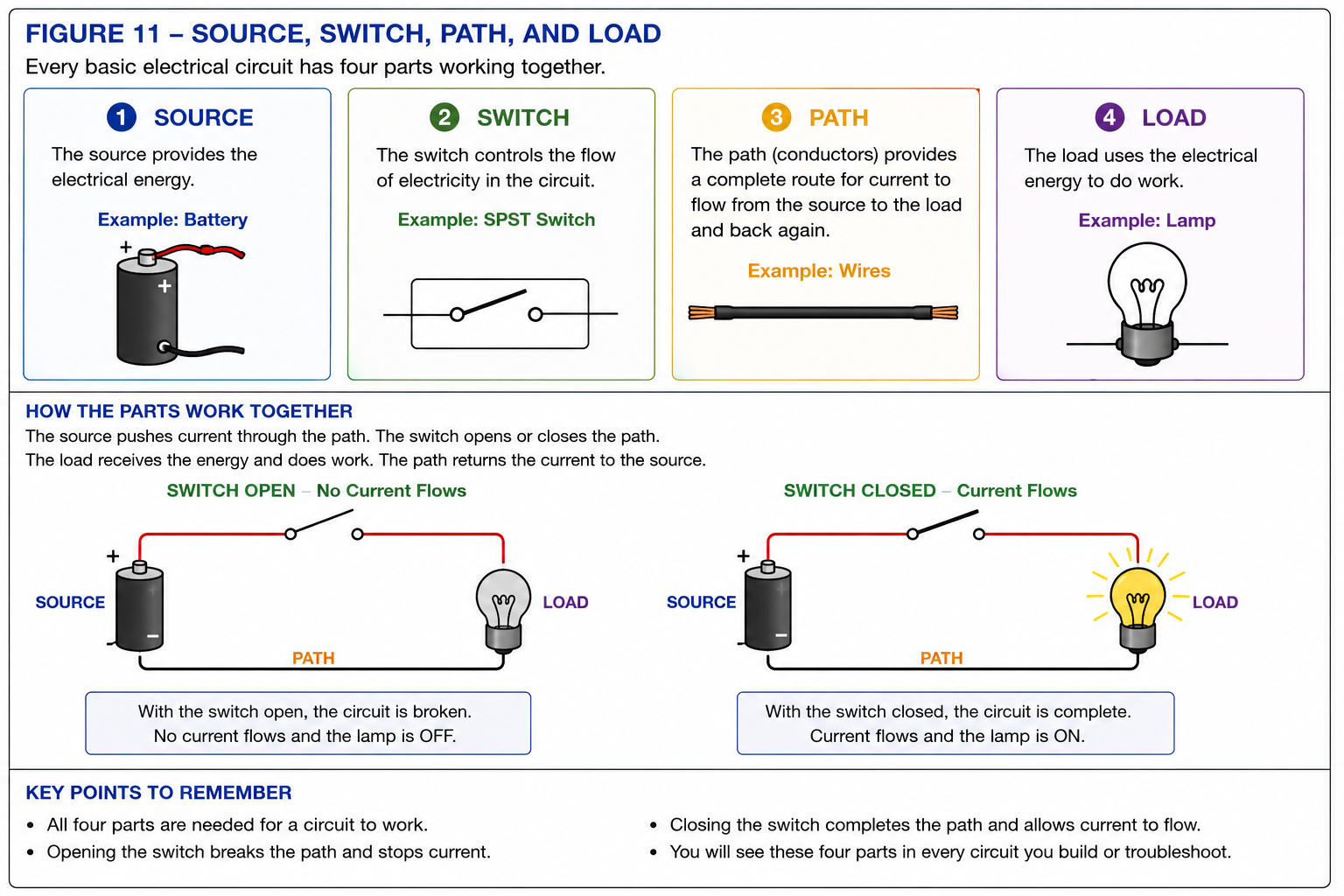
Source, switch, path and load in a simple electrical circuit.
A load operates only when there is a complete intended path.
If the switch opens, a wire breaks, or some other part
of the intended path becomes open, current through that
path stops.
If the path is complete, current can flow through the
load and return to the source.
Series Circuits
A series circuit has one current path.
When components are connected in series, the same current
passes through each component in that series path.
If any component in that single path opens, current stops
through the entire series circuit.
Current has only one route.
The same current passes through each series component.
An open anywhere interrupts current through the entire series circuit.
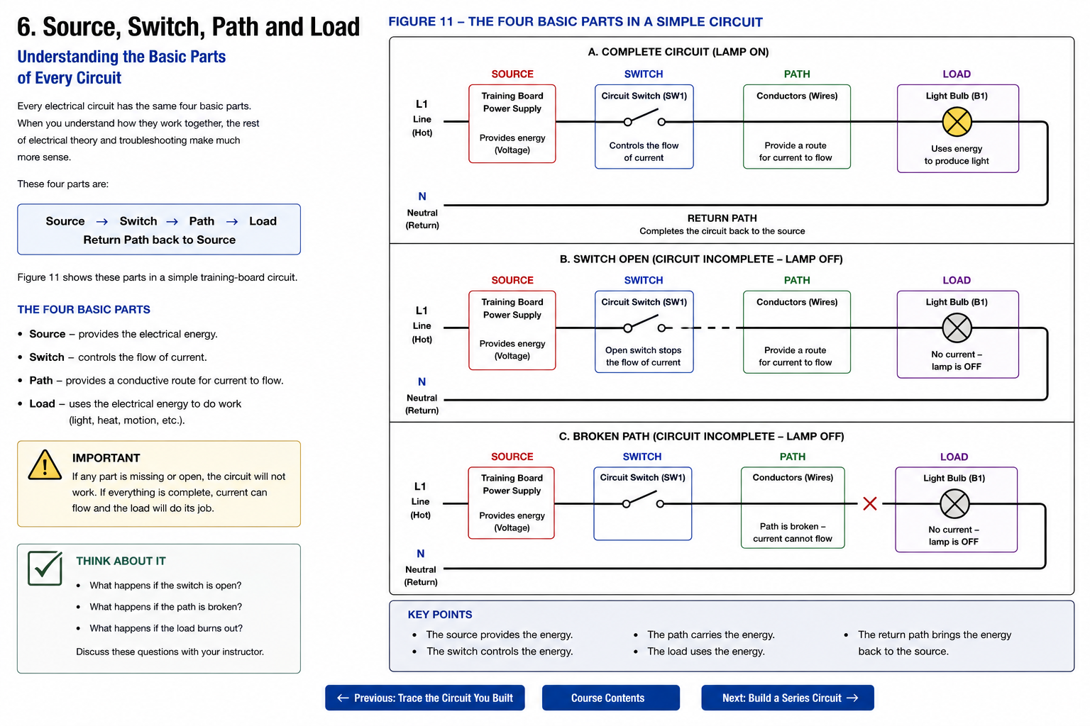
Example of source, switches, path and load connected
in a series circuit.
Voltage in a Series Circuit
The same current flows through all components in a series
path, but the source voltage can be divided among the loads.
The voltage drop across each load depends on that load’s
resistance or impedance.
If two identical resistive loads are connected in series,
they may divide the source voltage approximately equally.
If the loads are different, the voltage drops will also
be different.
The individual voltage drops in a series circuit add
up to the applied source voltage.
Series Switches in HVAC Control Circuits
HVAC equipment often uses several control devices in series.
A thermostat contact, pressure switch, limit switch,
condensate switch, or other safety device may all be part
of the same control path.
If any one of those series control devices opens,
current to the controlled load may stop.
This is one reason series circuits matter so much in troubleshooting.
If a contactor coil does not energize, you may need to
trace a whole series path of switches and controls to
find where the circuit opens.
Parallel Circuits
A parallel circuit provides more than one current path.
Each parallel branch is connected across the same source.
Because of that, each branch has approximately the source
voltage across it.
The current in each branch depends on the resistance or
impedance of that branch.
Current can flow through more than one branch.
Each branch is connected across the source.
Each branch current depends on that branch’s load.
Total Current in a Parallel Circuit
Current divides among the branches of a parallel circuit.
The total current supplied by the source is the sum
of the branch currents.
Total Current
IT =
I1 +
I2 +
I3 + …
Series and Parallel Circuit Examples
The examples below compare several common arrangements.
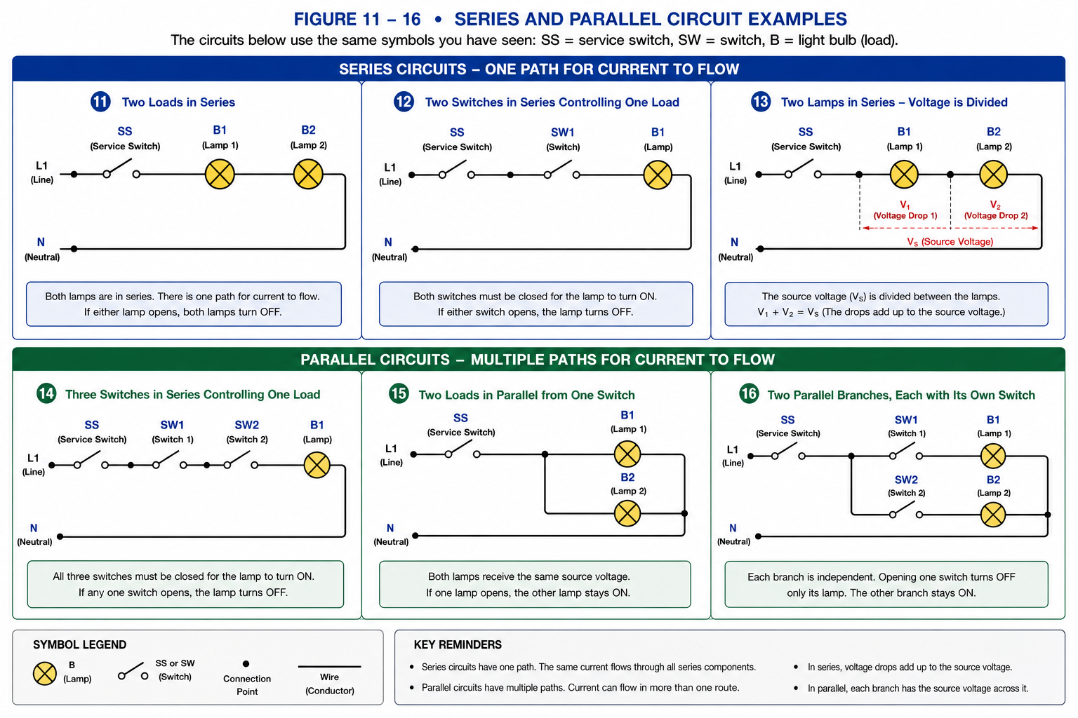
Examples of series and parallel circuits, including
multiple loads, multiple switches and independent branches.
Series vs. Parallel
| Series Circuit | Parallel Circuit |
|---|---|
| One current path | Multiple current paths |
|
Same current through components in the series path |
Branch currents may be different |
| Source voltage is divided among series loads | Each branch has approximately the source voltage |
| One open interrupts the entire series path |
One open branch does not necessarily stop the other branches |
How You Will See These in HVAC/R
Series Controls
Safety switches and control contacts are often placed
in series so that opening any required device stops
current to a control load.
Parallel Loads
Many equipment loads are connected in parallel so
each load receives the required source voltage and
can operate independently.
Combination Circuits
Real HVAC systems often contain both series and
parallel sections in the same schematic.
Troubleshooting
Knowing whether components are in series or parallel
helps you predict what your meter should read and
what should happen when a device opens.
What Is a Control Circuit?
A control circuit is a circuit used to control the operation
of equipment or another electrical circuit.
It may contain switches, thermostats, relay contacts,
safety devices, coils, electronic controls, and multiple
branches.
Control circuits are not defined by having only one load.
They are defined by what they do: they control equipment
operation.
Think About It
What happens to a series circuit if one switch opens?
What happens if one load in a series circuit opens?
What happens to the other branch of a parallel circuit
if one branch opens?
If two parallel loads are different sizes, should you
expect the same current in each branch?
Rules to Remember
A series circuit has one current path.
The same current flows through components in the
same series path.
Voltage drops across series loads add to the source voltage.
An open anywhere in a series path stops current
through that path.
A parallel circuit has multiple current paths.
Each parallel branch is connected across approximately
the same source voltage.
Total current in a parallel circuit is the sum
of the branch currents.
Real HVAC circuits often contain both series
and parallel sections.
Glossary
- Series Circuit
-
A circuit or portion of a circuit in which components
share a single current path. - Parallel Circuit
-
A circuit containing two or more branches connected
across the same source points. - Branch
- One of the separate current paths in a parallel circuit.
- Control Circuit
-
A circuit used to control the operation of equipment
or another electrical circuit. - Voltage Drop
-
The difference in electrical potential across a component
or portion of a circuit. - Open Circuit
-
A circuit or path that is interrupted so current cannot
flow through that path.
Do not just look at the components. Look at how they are connected.
Two switches may be in series.
Two loads may be in parallel.
A complete HVAC schematic may contain several series
and parallel sections at the same time.
When you learn to recognize the arrangement, you can
begin predicting what should happen before you ever
put a meter on the circuit.