BASIC ELECTRICAL FOR THE HVAC TECHNICIAN
Build a Series Circuit
Shop Project — Build, measure and explain a two-load series circuit.
In the previous lesson you learned how series and parallel
circuits behave. In this shop project you will build a
series circuit with two lamp loads, then use your meter
to verify the rules you just learned.
Safety First
This exercise was originally performed on a supervised
electrical training board.
Do not reproduce this exercise using household line
voltage as an unsupervised experiment.
Keep the circuit de-energized while wiring it.
Resistance measurements must also be made with the
circuit completely de-energized.
When measuring current, the meter must be inserted
in series with the circuit. Never place
an ammeter directly across the source.
What You Will Do
By the end of this project you should be able to:
Build a circuit containing two lamp loads in series.
Verify that the same current flows through the entire series path.
Measure the voltage drop across each lamp.
Verify that the voltage drops add up approximately
to the source voltage.
Explain what happens if any part of the series path opens.
Compare your actual meter readings with what you predicted.
The Circuit You Are Building
Figure 17 shows the training-board circuit for this project.
The service switch, circuit switch, and both lamp loads are
all in the same current path.
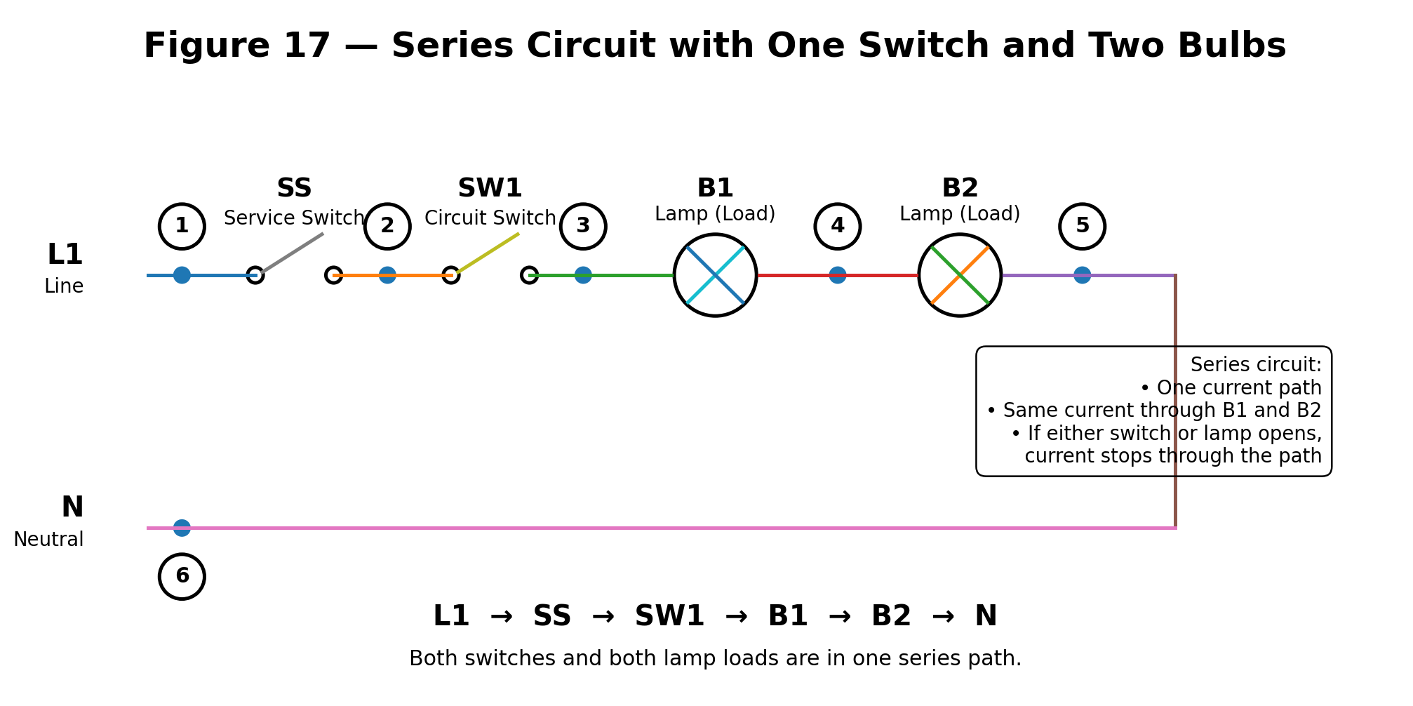
Series training-board circuit with SS, SW1, B1 and B2
all connected in one current path.
Remember the Series Circuit Rules
Current has only one route through the circuit.
The same current flows through every component
in the series path.
The source voltage is divided among the series loads.
The individual voltage drops add to approximately
the source voltage.
If any component opens, current stops through
the entire series path.
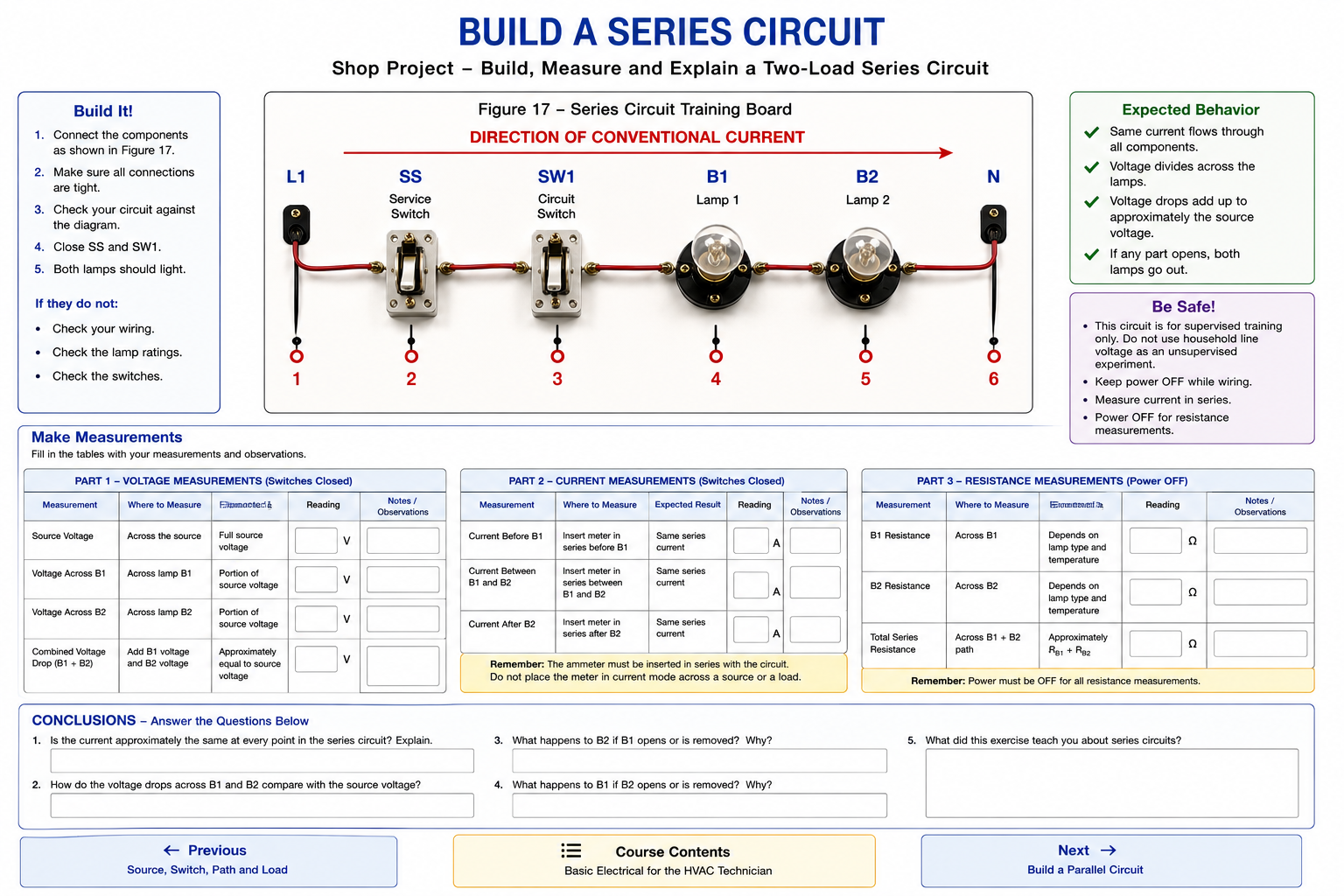
series-circuit exercise.
Build the Circuit
Keep the source disconnected while making the wiring connections.
1
Connect the Source to SS
Connect the line side of the training-board source
to the service switch SS.
2
Connect SS to SW1
Connect the output of SS to the circuit switch
SW1.
3
Connect SW1 to B1
Connect the output of SW1 to one side of lamp
B1.
4
Connect B1 to B2
Connect the other side of B1 directly to one side
of lamp B2.
5
Complete the Return Path
Connect the remaining side of B2 back to the
neutral or return side of the source.
6
Inspect the Circuit
Trace the complete path:
L1 → SS → SW1 → B1 → B2 → N
Verify that all connections match Figure 17
before applying power.
Predict Before You Measure
Before energizing the circuit, think about what you expect
your meter to show.
Will the current through B1 be the same as the current
through B2?
Will each lamp have the full source voltage across it?
What should happen to the circuit if either lamp opens?
What You Should Have Learned
A series circuit has only one current path.
The same current flows through B1 and B2.
Source voltage is divided between the series loads.
The voltage drops across B1 and B2 add to approximately
the source voltage.
Series resistances add together.
If one component opens, current stops through
the entire series path.
Do not stop at “both lamps came on.”
The important part of the exercise is understanding why
the current is the same through both lamps and why the
source voltage is divided between them.
When the measurements make sense to you before you take
them, you are beginning to troubleshoot instead of guess.